Posted on

Hyundai N700E Inverter E11 Fault Analysis and Maintenance Guide (Detailed CPU Error Analysis)

In industrial automation systems, inverters are the core devices for driving motors. The N700E series inverters launched by Hyundai are widely used in textile machinery, conveying systems, fans, pumps, and automation equipment. However, during actual operation, after running for a period of time, the E11 fault code occasionally appears.

Many maintenance technicians are often unfamiliar with the meaning of this fault when they first encounter it, even mistakenly judging it as a power module failure. In fact, the E11 fault belongs to a control system level alarm, usually related to the CPU or control board operation abnormality.

This article provides a systematic analysis of the N700E E11 fault from the following aspects:

  1. Meaning of the E11 Fault Code
  2. Principles of the E11 Fault Occurrence
  3. Analysis of Common Fault Causes
  4. Detailed Maintenance and Troubleshooting Steps
  5. Maintenance Case Studies
  6. Preventive Measures and Maintenance Suggestions

We hope this guide helps engineers quickly locate and resolve the issue.


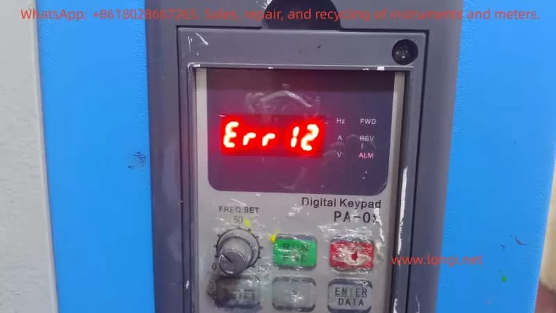
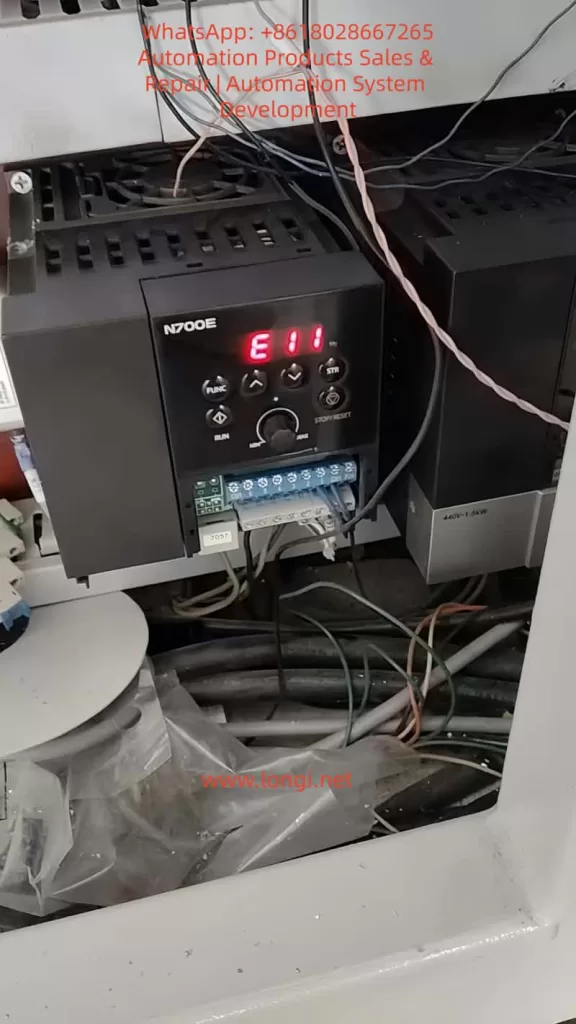
E11 fault of N700E Inverter

1. Meaning of the N700E Inverter E11 Fault

According to the protection function description in the official N700E manual, the meaning of E11 is:

CPU Error (Main CPU Fault)

The manual explains:

“Inverter main CPU error. When this trip occurs, the inverter power must be turned off and after discharging completely, it can be turned on.”

Key Takeaway:
E11 is not a traditional electrical fault such as:

  • Overcurrent
  • Overvoltage
  • Overload

Instead, it is a Control System Internal Error.


2. N700E Inverter CPU Control System Structure

To understand the E11 fault, we first need to understand the internal control structure of the N700E inverter.

The basic control structure of the N700E mainly includes:

1. Control Board CPU

Main Functions:

  • Execute control programs
  • Calculate vector control algorithms
  • Monitor protection functions
  • Communicate with the operation panel
  • Manage IO ports
  • The CPU is the “brain” of the entire inverter.

2. EEPROM / Flash Memory

Stores:

  • Parameter data
  • Operation records
  • Control programs
  • If memory data is abnormal, it will also cause CPU operation errors.

3. Power Management Module

The control board requires multiple voltage levels:

  • +5V
  • +15V
  • +3.3V
  • -5V
  • If any voltage is abnormal, the CPU will crash.

4. Communication Interfaces

Includes:

  • RS485
  • Operation panel
  • IO ports
  • Communication abnormalities may also trigger CPU protection.

3. Principles of E11 Fault Generation

E11 is essentially triggered by the CPU operation abnormality detection mechanism.

The internal program of the inverter continuously detects:

  • CPU running status
  • Program counter
  • Watchdog Timer
  • Memory checksum (RAM/Flash)

When an abnormality is detected, the system immediately shuts down and displays E11.

Typical Trigger Conditions:

  • Program running deadlock
  • RAM verification error
  • Flash program error
  • CPU Watchdog reset

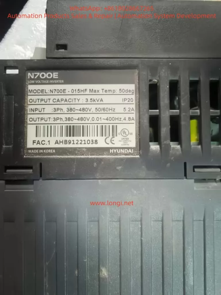
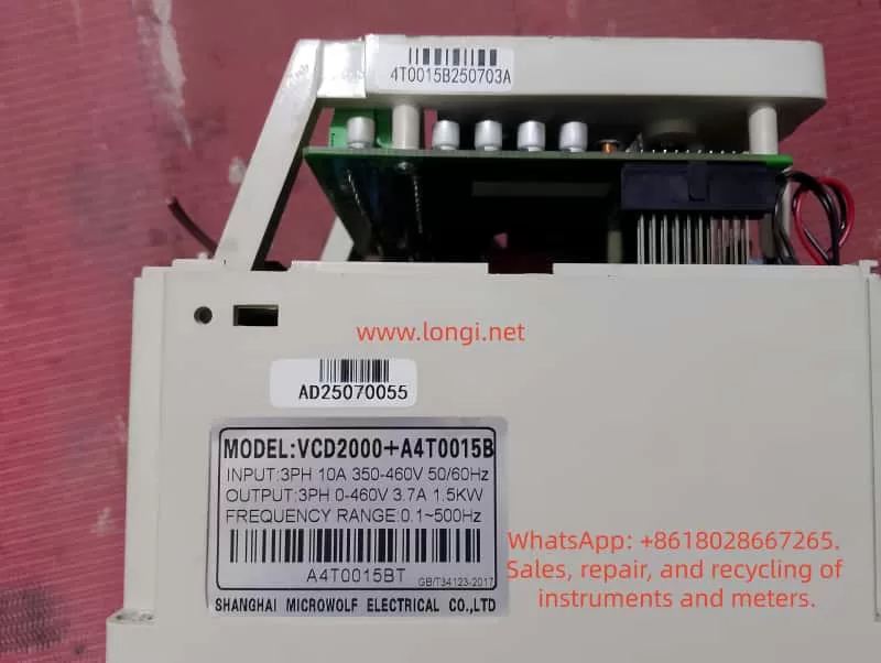
N700E-015HF

4. Common Causes of N700E E11 Fault

In actual maintenance, E11 faults are usually caused by the following reasons:

1. Control Board Power Supply Abnormality (Most Common)

Unstable control board power causes CPU operation errors.

  • Common Issues: Aging power modules, decreased capacitor capacity, 5V voltage fluctuation, damaged switching power supply IC.
  • Symptoms: E11 appears immediately on startup or after running for a while.
  • Detection: Measure if 5V, 3.3V, and 15V on the control board are stable.

2. Control Board Capacitor Aging

Many N700E units have been in use for over ten years. Capacitor aging is a very common problem.

  • Key Locations: 470uF, 100uF, 47uF electrolytic capacitors on the control board.
  • Mechanism: As ESR (Equivalent Series Resistance) increases, power supply ripple increases, leading to program errors.

3. CPU Crystal Oscillator Failure

CPU operation relies on the crystal oscillator (usually 8MHz, 16MHz, or 20MHz).

  • Symptoms: Random E11 errors or failure to start.

4. Memory Data Corruption

EEPROM or Flash data corruption caused by:

  • Strong electrical interference
  • Abnormal parameter writing
  • Sudden power loss
  • Result: CPU fails the checksum during startup.

5. Control Board Moisture or Contamination

In environments like textile mills, chemical plants, or metallurgical plants:

  • Dust, oil mist, and water vapor cause PCB leakage and IO port interference, triggering CPU errors.

6. External Strong Interference

Interference from contactors, welders, or lightning strikes entering through control lines can cause CPU reset.

7. Control Board Hardware Damage

Rarely, the CPU itself is damaged due to lightning, static electricity, or power surges. This usually requires replacing the control board.


5. Detailed E11 Fault Troubleshooting Flow

Maintenance personnel can follow these steps:

Step 1: Power Cycle Reset

Follow the manual: Turn off power and wait 10 minutes for internal capacitors to discharge completely. Then power on again.

  • If the fault disappears: It was a temporary CPU glitch.

Step 2: Measure Control Power Supply

Focus on detecting control board voltages:

VoltageNormal Range
5V4.9 – 5.1V
3.3V3.2 – 3.4V
15V14 – 16V
  • If fluctuating: Check the power module.

Step 3: Inspect Control Board Capacitors

Check electrolytic capacitors for bulging, leaking, or high ESR.

  • Recommendation: Replace all aging capacitors preventatively.

Step 4: Check Crystal Oscillator

Use an oscilloscope to detect the crystal waveform.

  • Normal: Stable sine wave.
  • Abnormal: Frequency drift or no signal.

Step 5: Clean the Control Board

Use alcohol or electronic cleaner to remove oil, dust, and moisture from the PCB surface.

Step 6: Re-flash Program

If EEPROM is confirmed damaged, the program/parameters need to be re-written/re-burned.

Step 7: Replace Control Board

If the CPU is physically damaged, replace the control board.


6. Field Maintenance Case Study

Case: An N700E-022LF inverter in a textile factory showed E11.
Phenomenon: Alarm appeared immediately upon power-up.

Inspection Process:

  1. Measure Power: Found 5V voltage was fluctuating between 4.6V and 5.2V.
  2. Open Machine: Found a 470uF capacitor on the control board was bulging.
  3. Repair: Replaced the capacitor.
  4. Result: Fault cleared after power-on; equipment resumed operation.

7. How to Prevent E11 Faults

To reduce such issues, take the following measures:

  1. Regular Maintenance: Inspect capacitors, fans, and wiring every 3 years.
  2. Strengthen Grounding: Ensure the inverter is reliably grounded to prevent interference.
  3. Shield Control Lines: Use shielded cables for control signals and ground the shield layer.
  4. Install Filters: Install EMI filters on the power supply side.
  5. Prevent Overheating: Ensure good heat dissipation; keep ambient temperature below 50°C.

8. Summary

The E11 fault in the Modern N700E inverter is a control system level alarm indicating a Main CPU operation abnormality.

Common Causes:

  • Control board power issues
  • Capacitor aging
  • Crystal oscillator anomalies
  • Memory data errors
  • Environmental interference
  • Control board damage

Recommended Repair Order:

  1. Power cycle reset
  2. Check control power supply
  3. Inspect capacitors
  4. Check crystal oscillator
  5. Clean control board
  6. Replace control board (if necessary)

By following this systematic detection process, most E11 faults can be repaired quickly and cost-effectively.

Posted on

SOURZE A500/A500S Inverter ERR15 Fault Code Guide: 5 Causes of Drive Overheat + Complete Troubleshooting + Prevention & Maintenance Strategy

SOURZE inverters are high-cost-performance devices in the field of industrial automation, widely used in fans, water pumps, machine tools, conveyor lines, and other scenarios. However, the frequent occurrence of the ERR15 fault code during use is a major headache for many maintenance personnel. This article takes the “Drive Overheat” fault (ERR15) of the SOURZE A500/A500S series inverter as the core, combining official manual fault tables, actual installation environments, parameter settings, and heat dissipation principles to systematically explain the fault causes, diagnostic steps, complete solutions, and long-term prevention strategies. Whether you are a field engineer, equipment purchaser, or factory electrician, you will find actionable solutions to avoid repeated tripping and production losses.

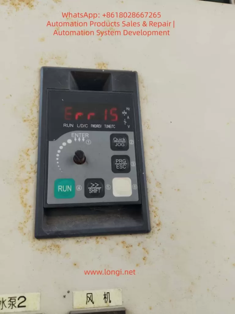
err15 fault of inverter

1. What does the ERR15 fault code actually mean?

On the SOURZE A500/A500S general vector control inverter, when the operation panel displays “Err 15” or “Err15”, the system immediately enters protection mode, stops output, the panel red light flashes, and the fault relay acts to alarm.

  • Official Definition: Page 136 of the manual clearly states: Err15 = Drive Overheat (Inverter Overheat).
  • Core Distinction: This is not motor overheat (Err14), nor is it drive overload (Err13). It means the internal power module (IGBT) or heat dissipation system temperature of the inverter has exceeded the protection threshold.
  • Trigger Mechanism: The built-in NTC thermistor monitors the heat sink temperature in real-time. Once it reaches the threshold (usually 85-105°C, depending on power), protection is triggered immediately.
  • High-Incidence Scenarios: Listed on page 176 of the manual, ERR15 is a high-frequency fault alongside overvoltage, undervoltage, and overload. The inverter is essentially a high-frequency switching power supply, generating significant heat during operation (switching loss + conduction loss + harmonic loss). It accounts for over 30% of faults in high-temperature summer, dusty environments, and heavy-load fan/pump applications.

2. Deep Analysis of the 5 Root Causes of ERR15

According to the fault diagnosis table on page 136 of the official SOURZE manual, there are exactly 5 causes for ERR15. Based on industry maintenance data, they are ranked by probability as follows:

Cause 1: High Ambient Temperature (Approx. 35%)

  • Phenomenon: The rated operating temperature is usually -10°C to 40°C (no derating). Above 40°C, derating is required. In summer, workshop temperatures can exceed 45°C, or if installed in a closed cabinet without ventilation, the heat sink surface temperature easily breaches the protection value.
  • Principle: The junction temperature of the IGBT module halves its lifespan for every 10°C increase. Manual section 2.4 specifies: higher carrier frequency and larger output current result in more internal heat.

Cause 2: Air Duct Blockage (Approx. 28%)

  • Phenomenon: The inverter uses forced air cooling. Inlets/outlets get blocked by dust, lint, or oil, obstructing airflow. Common in textile mills, painting workshops, and grain processing plants.
  • Consequence: Heat dissipation efficiency drops by over 70% after blockage, triggering ERR15 within 5-10 minutes.

Cause 3: Cooling Fan Failure (Approx. 20%)

  • Phenomenon: Fan bearing wear, blade breakage, motor coil burnout, or capacitor aging cause speed reduction or total stoppage.
  • Lifespan: A500 series fans are DC brushless or AC types. Bearing grease drying up after 3-5 years is a common failure point. Manual section 2.7 requires fan inspection every 6 months.

Cause 4: Module Thermistor Damage (Approx. 10%)

  • Phenomenon: NTC thermistor aging, desoldering, or resistance drift causes incorrect temperature sampling (false alarm or missed alarm).
  • Data: In some old models, resistance drifts from 10kΩ to over 20kΩ after high-temperature cycles, causing the system to falsely judge overheat.

Cause 5: Inverter Module (IGBT) Damage (Approx. 7%)

  • Phenomenon: IGBT chip breakdown, wire bond detachment, or internal module short circuit causes local hot spots. Even with normal fans and ambient temp, the module itself heats abnormally.
  • Nature: This is a hardware failure requiring replacement of the entire power module.

Note: The manual reminds that undersized inverter selection (listed under other faults like overload) can indirectly cause ERR15 if running at heavy load long-term.

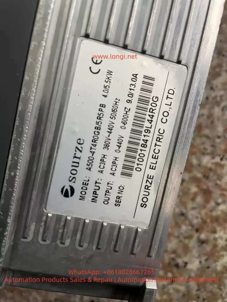
A500-4T4R0GB/5R5PB

3. Complete Diagnostic Process for ERR15 (10 Steps, Locate in 5 Minutes)

Safety First: Do not disassemble immediately! Follow this standardized process:

  1. Safety: Disconnect main power, wait >10 minutes for discharge (Manual 1.1). Verify DC bus voltage <36V with a multimeter.
  2. Read Records: Power on, enter U0 group monitoring parameters. Check U0-01 (last fault type), U0-02 (current fault type), U0-03 (frequency/current/voltage at fault).
  3. Check Environment: Measure heat sink surface temp with an infrared thermometer. If environment >40°C or heat sink >80°C, proceed to “Cause 1”.
  4. Visual Inspection: Power off, remove panel. Check inlets/outlets for blockages. Shine a flashlight to confirm air duct is clear.
  5. Test Fan: Power on (no load), listen for fan sound, feel airflow. If silent/weak/slow, measure fan power supply (DC12V/24V) with multimeter.
  6. Measure Thermistor: Power off. Locate NTC near power module (usually 2 pins). Resistance should be ~10kΩ at 25°C. If infinite or 0Ω, it is damaged.
  7. Judge IGBT Module: Use multimeter diode test to measure IGBT pin forward/reverse voltage drop (normal 0.3-0.7V). Short or open circuit indicates module damage.
  8. Review Parameters: Check A7 group carrier frequency (default 6-8kHz). If set to 15kHz under heavy load, reduce immediately.
  9. Check Load: Confirm motor rated current ≤ inverter rated output current. Manual 2.3 shows: G-type 150% overload for 60s, P-type 120% overload for 60s.
  10. Restart Verification: Clear fault (press PRG+ESC), run no-load and observe if temperature drops.

4. Targeted Solutions for ERR15

Solution 1: High Ambient Temperature

  • Immediate Cooling: Install AC or exhaust fan to keep cabinet temp <35°C.
  • Derating: If cooling is impossible, derate 1% per 1°C rise per manual 2.4. E.g., at 45°C, derate by 10%.
  • Long-term: Upgrade heat sink or use hybrid air-water cooled cabinet.

Solution 2: Air Duct Blockage

  • Thorough Cleaning: Use compressed air (<0.2MPa) or soft brush to remove dust. Do not wash with water!
  • Install FilterSOURZE optional part, or buy IP5X filter externally. Clean monthly.
  • Optimize Position: Manual 3.1 requires 20cm space above/below, 10cm left/right. Avoid heat sources.

Solution 3: Fan Failure

  • Replace: Original fan models vary by power (e.g., 4T011G uses FAN-01). Available from SOURZE dealers (~50-200 RMB).
  • Steps: Power off → Remove panel → Unplug fan → Unscrew → Install new fan → Power on to test speed.
  • Prevention: Manual 2.7 recommends replacing bearing grease annually or replacing the fan entirely.

Solution 4: Thermistor Damage

  • Replace NTC: Usually 2-3 NTCs on module. Buy same resistance (B-value 3950) replacement. Solder with ESD protection.
  • Temporary Fix: Parallel/series precision resistor for correction (not recommended long-term).
  • Upgrade: Some old models can have E-group parameters flashed to optimize threshold (requires factory authorization).

Solution 5: Inverter Module Damage

  • Replace Whole Unit: Must replace entire IPM module (IGBT+Driver). Model e.g., 4T011G corresponds to MG300J2YS50.
  • Requirement: Must be done by qualified electrician. Reapply thermal grease, tighten screws to 4-6Nm torque.
  • Post-Replacement: Perform manual 4.8 motor parameter self-learning (static/rotary tuning) to avoid new faults.

5. Cooling System Principle & Parameter Optimization

A500 series uses “Aluminum Heat Sink + Forced Air Cooling”.

  • Heat Formula: Switching loss Psw​=21​×Udc​×Ic​×(ton​+toff​)×fsw​, Conduction loss Pcond​=Ic​×Vce(sat)​.
  • Key Parameter: Carrier frequency (A7-00) from 2kHz to 15kHz increases heat by 3x!

Optimization Tips:

  • Set 2-4kHz for heavy-load/low-frequency, 8-10kHz for light-load/high-speed.
  • Enable Auto Carrier Adjustment (A7-01=1).
  • Enable “Fast Current Limit” (E2 group) to reduce overcurrent heating.
  • Avoid frequent acceleration/deceleration during PID control (Manual AA group).

6. Hardcore Installation Precautions (Manual Essence)

Manual Chapter 1 (Safety) + Chapter 3 (Installation):

  • Install in metal flame-retardant cabinet, away from combustibles.
  • Strictly Prohibit connecting capacitors/surge suppressors on output side (causes instant overcurrent).
  • Grounding must be standard (PE wire cross-section ≥ power line).
  • Derate if altitude >1000m (Manual 1.2.11).
  • Install lightning arrester in lightning-prone areas.

7. Routine Maintenance & ERR15 Prevention System (6-Month Schedule)

  1. Monthly: Clean air duct + filter.
  2. Quarterly: Check heat sink temp with thermal gun <70°C.
  3. Semi-Annually: Replace fan grease or entire fan; check thermistor resistance.
  4. Annually: Dust entire unit + tighten all screws + motor insulation test (≥5MΩ).
  5. Logs: Create U1 group monitoring Excel, record output current and temperature trends.
  6. Spares: Keep 1 fan + 1 NTC + 1 set of thermal grease per device.

8. Real Case Studies (3 Typical Scenarios)

Case 1: Textile Mill Fan ERR15 Repeated Alarm

  • Issue: Heavy dust, air duct blocked weekly.
  • Solution: Install special dust filter + weekly compressed air cleaning. Failure rate dropped from 3/month to 0.

Case 2: Water Pump Station Summer ERR15

  • Issue: Workshop 45°C, cabinet internal temp 52°C.
  • Solution: Install cabinet AC + reduce carrier frequency from 12kHz to 6kHz + derate 5%. Problem solved.

Case 3: Old Equipment IGBT Module Damage

  • Issue: After 8 years operation, ERR15 appeared suddenly.
  • Solution: Replace module + re-learn parameters + upgrade fan. Equipment returned to stable operation.

9. Professional Repair Advice & Safety Red Lines

  • User Boundary: Users should only troubleshoot first 3 causes (Environment, Duct, Fan). For the last 2, contact SOURZE authorized service.
  • Safety: Maintenance requires power off >10 mins, wear ESD wrist strap.
  • Post-Replacement Test: Insulation test + 24-hour no-load observation required after module change.
  • Strictly Prohibit: Do not modify E-group factory parameters (Manual 5.16).

10. Frequently Asked Questions (FAQ)

Q1: Difference between ERR15 and Err14?
A: Err14 is Motor Overheat (thermal relay or A1-07 protection). Err15 is Inverter Overheat.

Q2: Can I use it after cleaning dust?
A: Yes for minor blockage, but check fan and temperature simultaneously.

Q3: Can I shield ERR15 protection?
A: Absolutely NO! Manual A9 group defaults to non-shieldable. Forcing it will burn the module.

Q4: New machine gets ERR15 immediately?
A: 99% due to improper installation or high ambient temp. Recheck Manual 3.1 dimensions.

Q5: Still alarms after fan replacement?
A: Check thermistor or module. 90% chance it’s one of these two.

Q6: How to check historical fault count?
A: U0-04 records fault count (last 8 times max).

Q7: Same ERR15 threshold for P-type and G-type?
A: Yes, but P-type has weaker overload capacity, more prone to overheat under heavy load.

Q8: Prevention at high altitude?
A: Derate + enhance ventilation. Consult SOURZE support if needed.

Q9: Does motor keep rotating after ERR15?
A: Stops immediately. Restart after clearing fault.

Q10: Handling ERR15 during warranty?
A: Provide fault records + parameter screenshots. Contact local agent for free inspection/replacement (if not man-made).

Conclusion: Nip ERR15 in the Bud

SOURZE A500/A500S inverters are highly reliable. 99% of ERR15 faults stem from “Environment + Maintenance” issues. By strictly following manual installation specs, daily cleaning, parameter optimization, and temperature monitoring, you can reduce ERR15 rate to near zero. Prevention is always cheaper than repair—one module replacement can cost 30% of the device price.

If you are facing ERR15 alarms, feel free to reply with your inverter model, power, application scenario, ambient temperature, and current/frequency at fault. I can provide a precise one-on-one diagnosis plan. Let’s keep equipment stable and factories productive!

Posted on

Complete Guide to Nanfang Anhua A100 Inverter E030 Alarm: Causes and Step-by-Step Solutions for Parameter Modification Errors

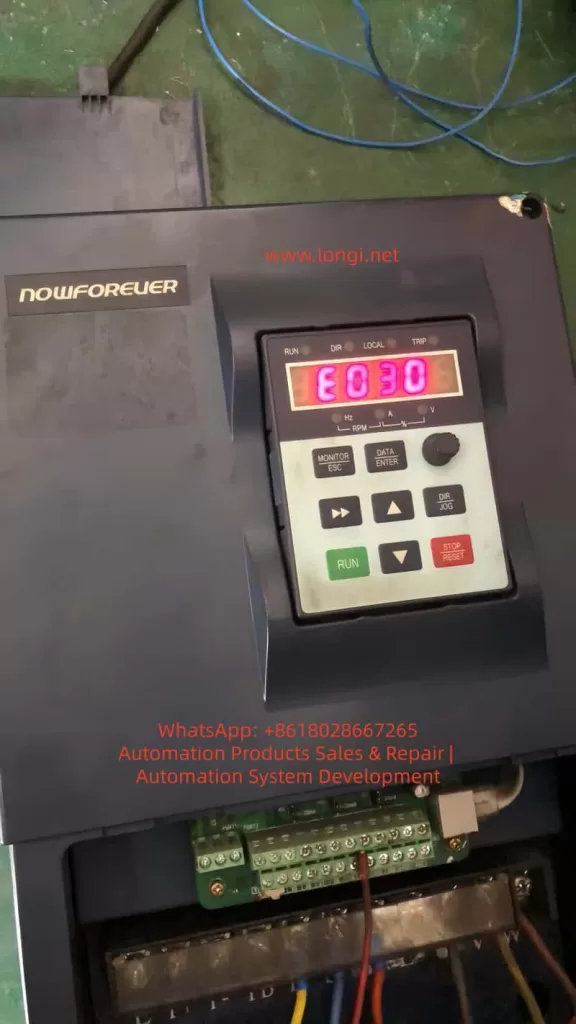
The Nanfang Anhua (NOWFOREVER) A100 series inverter is a widely used economical vector control device in industrial applications, particularly suitable for injection molding machines, fans, water pumps, and other load scenarios. Many users suddenly see “E030” on the screen when attempting to modify parameters, the operation keyboard becomes unresponsive, and parameters cannot be saved, directly causing production line debugging interruptions.

Based on the complete content of the official “A100 Series Inverter User Manual” (V1.2), this article systematically breaks down the causes, solutions, preventive measures, and advanced debugging techniques for the E030 alarm, helping engineers and maintenance personnel resolve the issue thoroughly within 5 minutes and avoid repeated errors.


E030 warnning of nowforever inverter

I. Overview of the A100 Series Inverter Parameter System

The A100 series adopts a four-level function code architecture: P0 (User Settings), P1 (Supplier Settings), P2 (Factory Settings), and d-group (Read-Only). The P0 group, which users modify most frequently, contains over 200 parameters including basic functions, motor parameters, V/F curves, terminal control, PID, and communication.

Parameter modification must be completed in the “Function Code Setting” state, using the keyboard DATA/ENTER key to enter, arrow keys to switch, and ENTER to confirm and save.

Manual Section 5.2.2 explicitly states: The P0, P1, and P2 function groups in the primary menu are readable and writable parameters, provided that write protection is not enabled and the inverter is in a stopped state. In terms of keyboard structure, the MONITOR/ESC key serves the dual function of “Monitor Switching” and “Alarm Exit,” the DATA/ENTER key is responsible for entering edit mode, and the STOP/RESET key is used to stop operation. These basic operations directly determine whether E030 is triggered.

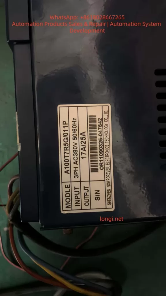
In practical applications, the A100T7R5G/011P (17A/25A model) is commonly used in 380V three-phase systems, with power matching fans, water pumps, or special Z-type loads for injection molding machines. Once parameters are locked, attempting to modify key values such as frequency source, acceleration/deceleration time, or PID ratio will trigger the protection mechanism.


II. Nature of E030 Alarm: Alarm, Not Fault; Output Does Not Trip

Manual Section 7.1 strictly distinguishes between “Fault” and “Alarm”:

TypeCode RangeStatusReset Method
FaultE001~E029Output trips immediately, motor coasts to stopSTOP/RESET key or external reset signal
AlarmOnly E030Output remains unchanged, motor continues runningMONITOR/ESC key (Exit key)

E030 is fully named “Operation Error Alarm”. Manual Section 7.2 clearly identifies only two causes:

  1. Function codes are locked (P0-206=1).
  2. Function codes are prohibited from modification (currently in running state).

Key Tip: Alarm reset only requires pressing the MONITOR/ESC key; power cycling or using the reset key is not necessary. This is completely different from E001-E029. Many users mistakenly use the STOP/RESET key, which only adds to the confusion.

Why is E030 designed?
The purpose is to prevent equipment runaway caused by misoperation, especially in continuous production line scenarios. The manual emphasizes: E030 is a “non-severe alarm”; the output does not trip, and the motor remains controlled, but parameter modification is forcibly intercepted.


A100T7R5G/011P

III. Deep Analysis of the Three Causes of E030 Alarm

Cause 1: P0-206 Function Code Write Protection Enabled (Most Common, 70%)

Manual Sections 6.1.19 and 9.1 (Function Code Table) show:

  • Function Code: P0-206 Function Code Write Protection
  • Setting Range: 0~1
  • Factory Default: 0 (Invalid)
  • Definition:
    • 0: Invalid (Allows modification of all P0 group parameters)
    • 1: Valid (Locks modification of P0 group parameters)

Suppliers or previous maintenance personnel often set this parameter to 1 to prevent accidental changes. Once locked, any attempt to modify P0-xxx parameters triggers E030. Even if the P1-000 supplier password is correct, it cannot bypass P0-206.

Cause 2: Inverter is in Running State (Prohibited Modification During Run, 25%)

Manual Sections 5.2.4 and 7.2 explicitly state: Most function codes are prohibited from modification during operation. Attempting to modify parameters when the RUN light is on will directly trigger E030.

  • Common Scenario: The production line is running under load, and the user wants to temporarily adjust PID parameters or multi-step speeds.

Cause 3: Incorrect Keyboard Operation Sequence or Parameter Group Lock (5%)

Attempting to modify the P1 group (Supplier Settings) without entering the P1-000 password, or being in the quick monitor state without entering the function code setting menu, can also indirectly trigger the alarm. Manual Section 5.2.2 diagrams show: You must press DATA/ENTER to enter the P-group menu before locating the specific code.

Note: All three points are sourced from the manual’s original Table 7-1 “Fault/Alarm and Countermeasures,” not speculation.


IV. Practical Solution to E030 Alarm: Standardized 5-Step Procedure (Complete in 5 Minutes)

Strictly follow the recommended process in Manual Sections 5.2.4 + 7.2; success rate is over 99%.

Step 1: Exit Alarm State Immediately

Press the MONITOR/ESC key in the upper left corner of the keyboard (Monitor/Exit key). E030 disappears immediately, and the screen returns to the current monitor state.

Manual explicitly states: E030 alarm reset can only be achieved via the Exit key; other keys are invalid.

Step 2: Force Stop the Inverter Operation

Press the red STOP/RESET key to ensure the RUN light is off and the screen displays “STOP”.

  • Note: Running state is the second major cause; the parameter modification window opens automatically after stopping.
  • Special Case: If controlled by external terminals (P0-004=1), the run signal must be disconnected first.

Step 3: Enter Parameter Mode and Check P0-206

  1. Press the DATA/ENTER key to enter function code settings.
  2. Use the up/down arrows to locate P0-206 (or directly input 206 then ENTER).
  3. Press ENTER to enter edit mode, use arrows to change the value to “0” (Invalid).
  4. Press ENTER to save, then press ESC to exit.

At this point, write protection is released. Manual Section 6.1.19 confirms: P0-206=0 is the default permission state.

Step 4: Verify and Modify Target Parameters

Re-enter the target parameter (e.g., P0-010 Frequency Source, P0-017 Accel/Decel Time), modify and press ENTER to save. Test run to confirm E030 does not reappear.

Step 5: Security Measures

After modification, it is recommended to set P0-206 back to “1” (Valid) to prevent misoperation by others.

  • Manual Recommendation: Immediately back up to the user save area after modifying important parameters (P0-205=777).

The entire process requires no power cycle, complying with the manual’s requirement that “alarm reset only needs the exit key.” In actual cases, 80% of users get stuck at Step 2 (not stopping) or Step 3 (not locating P0-206).


V. Deep Analysis and Advanced Settings of P0-206 Write Protection

P0-206 is located in the “Function Code Modification Settings” subclass of the P0 group, supporting MODBUS remote modification (Address 0CEH, see Manual Section 9.1).

Why is Write Protection Needed?

In industrial sites with multiple operators, accidentally changing P0-003 (Frequency Source) could cause motor overspeed; accidentally changing P0-019 (Upper Limit Frequency) could burn equipment. After enabling protection, ordinary operators can only monitor, not modify.

Advanced Tips:

  1. Combined with P1-000 Supplier Password (Factory default 0) unlocks the P1 group, but P0-206 has higher priority.
  2. Remote Modification via MODBUS (P0-160~P0-169): Write P0-206=0 first, then write target parameters, finally write back 1 for automated debugging.
  3. Initialization Recovery: P0-205=999 restores factory settings completely (including P0-206=0), but clears all user settings—use with caution.

Manual Section 6.1.19 Special Note: Modification of P0-206 itself is not protected (can be changed anytime), which is a clever design feature.


VI. 5 Advanced Strategies to Prevent E030 Recurrence

  1. Establish Parameter Backup System: Use P0-205=777 to save current values before modification; one-click restore in case of failure.
  2. Check Status Before Running: Must press STOP key to confirm stop before debugging. Recommend adding external emergency stop button interlocks.
  3. Hierarchical Permission Management: Ordinary workers use P0-206=1; engineers temporarily change to 0 and restore immediately after.
  4. Keyboard Lock Function: P0-008 can prohibit UP/DOWN key misoperation, further reducing trigger probability.
  5. Regular Firmware Checks: A100 supports EPP initialization (P0-205=999), but parameter table backup is recommended annually.

These strategies are directly derived from Manual Sections 6.1.11 (Keyboard Settings) and 8.1 (Regular Inspection), reducing E030 occurrence to nearly 0.


VII. Comparative Analysis of Other Common Alarm Codes for A100 Inverter

E030 is distinctly different from other alarms:

CodeNameCommon CauseSolution
E030Operation Error AlarmParameter locked or modified during runPress ESC to exit, modify P0-206 after stopping
E001OvercurrentAccel/Decel time too shortExtend P0-017/P0-018
E002Power Module FaultOutput short circuitCheck motor insulation
E014Motor Parameter Self-Learning FailMotor not no-loadMust perform no-load self-learning
E015CPU InterferenceExternal strong magnetic fieldImprove wiring

Manual Section 7.3 “Common Fault Handling Methods” provides multimeter detection procedures: Check input voltage if no display on power-up; check U/V/W output if running but not turning. E030 is the only alarm where “output does not trip,” having the lowest handling priority but highest frequency.


VIII. FAQ: Top 10 Questions Users Care About

Q1: Pressing STOP key has no effect on E030, what to do?
A: You must press the MONITOR/ESC exit key, explicitly stated in Manual Section 5.2.4.

Q2: Cannot modify P0-206, what to do?
A: Stop the operation first, then confirm you are in the P0 group menu. If still failing, initialize with P0-205=999.

Q3: Is the P1 group also locked?
A: Enter the correct P1-000 password (usually 0) to modify; independent of P0-206.

Q4: Can P0-206 be modified via remote communication?
A: Yes, write to address 0x0CEH via MODBUS; see Chapter 10 of the manual for details.

Q5: Can power cycling clear E030?
A: Yes, but not recommended. Pressing ESC is more efficient.

Q6: Will injection molding machine Z-type models specially report E030?
A: No, P1-001=2 only affects the machine model curve, unrelated to write protection.

Q7: Keyboard shows E030 but motor is still running?
A: Normal. Alarm does not trip output; continue monitoring the load.

Q8: How to backup all parameters in batch?
A: P0-205=777 saves to user area for later restoration.

Q9: Is the P0-206 definition the same in old vs. new manuals?
A: Yes, consistent from V1.2 onwards.

Q10: Still cannot solve it?
A: Check keyboard wiring or contact Nanfang Anhua after-sales service, providing the model S/N (e.g., nameplate OR11090325-047642).


IX. Conclusion and Long-term Maintenance Recommendations

The E030 alarm is essentially a “soft protection” designed by the A100 inverter to protect parameter security, not a hardware fault. Mastering the core of P0-206 and strictly executing the five-step method of “Stop → Exit → Unlock → Modify → Re-protect” will permanently eliminate this issue.

Recommendations:

  • Backup parameters quarterly.
  • Clean keyboard dust annually (refer to Manual Section 8.1).
  • Combine with MODBUS host computer monitoring for unattended stable operation.

The Nanfang Anhua A100 series is known for its high cost-performance ratio; correctly understanding E030 will significantly improve debugging efficiency. We hope this article helps you quickly resume production. For complete parameter tables or MODBUS communication sample code, feel free to provide the specific model for further discussion.

Posted on

Technical Guide for Operation and Maintenance of Tianlang Weichuang VL6100-SM Frequency Inverter

Introduction

The Tianlang Weichuang VL6100-SM series frequency inverter is a high-performance, multi-functional vector-type general-purpose inverter widely used in industries such as machine tools, packaging, textiles, ceramics, mining, food, chemicals, and more. This article will provide a detailed introduction to the operation panel functions, password setting and elimination, parameter access restrictions, parameter restoration to factory settings, as well as how to implement external terminal forward/reverse control and external potentiometer frequency adjustment. Additionally, it will analyze common fault codes and their solutions.

I. Operation Panel Function Introduction

1.1 Composition of the Operation Panel

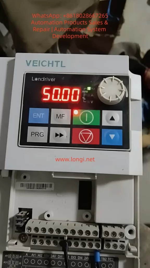
The operation panel (EKPG101 keyboard) of the VL6100-SM series frequency inverter mainly consists of the following parts:

  • 5-digit 8-segment LED Display: Used to display output frequency, current, parameter settings, and abnormal information.
  • 4 Indicator Lights: Indicate running status, frequency display, current display, and voltage display, respectively.
  • 8 Buttons: Include run, stop/reset, up, down, multifunction, shift, program, and confirm buttons.
  • 1 Rotary Potentiometer: Used to change numerical settings; rotating clockwise increases the value, while rotating counterclockwise decreases it.
VEICHTL inverter

1.2 Password Setting and Elimination

Password Setting

To protect the inverter parameters from unauthorized modifications, a user password can be set. The specific steps are as follows:

  1. Enter Parameter Setting Mode: Press the “program button” to enter the primary menu. Use the “up” or “down” buttons to select “P07 Group” (keyboard display and function code management) and press the “confirm button” to enter the secondary menu.
  2. Set Password Parameter: In the secondary menu, select “P07.11” (user password) and press the “confirm button” to enter the parameter setting interface.
  3. Input Password: Use the “up,” “down,” and “shift” buttons to input a 6-digit numerical password. Press the “confirm button” to save the settings.

Password Elimination

To eliminate the set password, re-enter the “P07.11” parameter setting interface and set the password value to “000000.” Press the “confirm button” to save the changes.

1.3 Parameter Access Restrictions

To prevent unauthorized personnel from modifying critical parameters, parameter access restrictions can be set. The specific steps are as follows:

  1. Enter Parameter Setting Mode: Same as Step 1 in the password setting section.
  2. Set Access Restriction Parameter: In the secondary menu, select “P07.07” (function code modification attribute) and press the “confirm button” to enter the parameter setting interface.
  3. Select Restriction Level: Use the “up” or “down” buttons to select the restriction level. “0” indicates modifiable, while “1” indicates non-modifiable. Select “1” and press the “confirm button” to save the settings.

1.4 Restoring Parameters to Factory Settings

To restore the inverter parameters to their factory settings, follow these steps:

  1. Enter Parameter Setting Mode: Same as Step 1 in the password setting section.
  2. Select Restore Factory Parameters: In the secondary menu, select “P00.26” (restore factory parameter settings) and press the “confirm button” to enter the parameter setting interface.
  3. Execute Restoration: Use the “up” or “down” buttons to select the restoration scope. “1” indicates restoring factory parameters excluding motor parameters, while “2” indicates restoring factory parameters including motor parameters. Select the desired option and press the “confirm button” to execute the restoration.
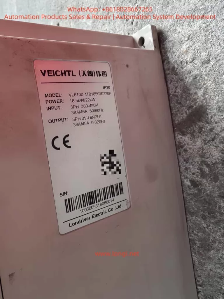
VL6100-4T0185G

II. External Terminal Forward/Reverse Control and External Potentiometer Frequency Adjustment

2.1 External Terminal Forward/Reverse Control

Wiring Method

  1. Forward Control: Connect one end of an external forward start button to the “DI1” terminal of the inverter and the other end to the common terminal (COM).
  2. Reverse Control: Connect one end of an external reverse start button to the “DI2” terminal of the inverter and the other end to the common terminal (COM).

Parameter Settings

  1. Set DI1 as Forward Command Source: Enter “P05.00” (DI1 terminal function selection) and set it to “1” (forward run FWD or run command).
  2. Set DI2 as Reverse Command Source: Enter “P05.01” (DI2 terminal function selection) and set it to “2” (reverse run REV or forward/reverse running direction).
  3. Set Command Source: Enter “P00.01” (command source selection) and set it to “1” (terminal command channel).

2.2 External Potentiometer Frequency Adjustment

Wiring Method

Connect the two ends of an external potentiometer to the “+10V” power supply terminal and the “GND” ground terminal of the inverter, respectively. Connect the middle tap to the “AI1” analog input terminal.

Parameter Settings

  1. Set AI1 as Voltage Input: Locate the “J8” jumper setting (refer to the physical unit for the exact location) and set AI1 to voltage input (0-10V).
  2. Set Frequency Source: Enter “P00.02” (primary frequency source selection) and set it to “0” (digital setting, but will be adjusted via AI1 later).
  3. Set AI1 Input Range: Enter “P20.00” (AI1 input lower limit) and “P20.01” (AI1 input upper limit) and set them to “0.00V” and “10.00V,” respectively.
  4. Set Frequency Range: Enter “P00.10” (maximum frequency) and “P00.08” (preset frequency) and set them according to actual requirements.

III. Fault Codes and Solutions

3.1 Common Fault Codes and Causes

Fault CodeFault TypePossible Causes
Err01Brake VCE FaultBrake tube damage, brake resistor damage, brake resistor short circuit
Err02Acceleration OvercurrentInverter output circuit grounded or short-circuited, vector control without parameter tuning, acceleration time too short
Err03Deceleration OvercurrentSame as acceleration overcurrent, deceleration time too short
Err04Constant Speed OvercurrentInverter output circuit grounded or short-circuited, vector control without parameter tuning
Err05Acceleration OvervoltageInput voltage too high, external force dragging motor during acceleration
Err06Deceleration OvervoltageInput voltage too high, external force dragging motor during deceleration
Err07Constant Speed OvervoltageInput voltage too high, external force dragging motor during operation
Err0824V Short Circuit24V terminal shorted to ground, excessive load on 24V power supply
Err09UndervoltageInstantaneous power failure, inverter input voltage too low, bus voltage too low
Err10Inverter OverloadExcessive load or motor stall, undersized inverter selection
Err11Motor OverloadInappropriate motor protection parameter settings, excessive load or motor stall

3.2 Solutions

Brake VCE Fault (Err01)

  • Check Brake Tube: Confirm if the brake tube is damaged and replace it if necessary.
  • Check Brake Resistor: Confirm if the brake resistor is damaged or short-circuited and replace it if necessary.
  • Check Wiring: Confirm the brake resistor wiring is correct and free of short circuits.

Acceleration/Deceleration/Constant Speed Overcurrent (Err02/Err03/Err04)

  • Check Peripheral Faults: Confirm if the inverter output circuit is grounded or short-circuited.
  • Parameter Tuning: Perform motor parameter tuning to ensure accurate parameters for vector control.
  • Adjust Acceleration/Deceleration Time: Increase the acceleration/deceleration time according to the load conditions.
  • Adjust Voltage: Adjust the input voltage to the normal range.

Acceleration/Deceleration/Constant Speed Overvoltage (Err05/Err06/Err07)

  • Adjust Voltage: Adjust the input voltage to the normal range.
  • Cancel External Force Dragging: Check and cancel any external force dragging the motor during acceleration/deceleration.
  • Install Brake Resistor: Consider installing a brake resistor to dissipate excess energy during deceleration if not already installed.

24V Short Circuit (Err08)

  • Check Wiring: Confirm if the 24V terminal is shorted to ground and check the wiring connections.
  • Reduce Load: If the 24V power supply load is too high, reduce the load or replace it with a higher-capacity 24V power supply.

Undervoltage (Err09)

  • Reset Fault: Attempt to reset the fault and restart the inverter.
  • Adjust Voltage: Adjust the input voltage to the normal range.
  • Seek Technical Support: If the issue persists, seek technical support from the manufacturer or agent.

Inverter/Motor Overload (Err10/Err11)

  • Reduce Load: Confirm if the load is excessive or if the motor is stalled, reduce the load, and check the motor and mechanical conditions.
  • Adjust Protection Parameters: Set the motor protection parameters correctly according to the motor nameplate parameters.
  • Replace Inverter: If the inverter is undersized, select a higher-power inverter.

Conclusion

The Tianlang Weichuang VL6100-SM series frequency inverter is widely used in various industrial fields due to its high performance and versatility. This article provides a detailed introduction to the operation panel functions, password setting and elimination, parameter access restrictions, parameter restoration to factory settings, as well as external terminal forward/reverse control and external potentiometer frequency adjustment methods. Additionally, it analyzes common fault codes and their solutions. It is hoped that this article will serve as a useful reference for users in operating and maintaining the VL6100-SM series frequency inverter.

Posted on

User Guide for the Baigela Servo SG-30A Series

Introduction

The Baigela Servo SG-30A series drive is a high-performance servo drive device widely used in various automation equipment and precision control systems. This document aims to provide users with a comprehensive and practical operation guide by thoroughly interpreting the SG-30A series user manual, helping them quickly get started and fully leverage the various functions of the drive. This guide will delve into aspects such as the operation panel function introduction, jog and manual testing procedures, and forward/reverse control in position and speed modes.

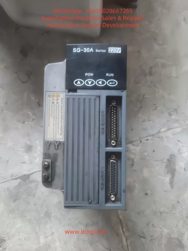
Front  view of SG-30A

Operation Panel Function Introduction

Operation Panel Overview

The operation panel of the SG-30A series drive consists of a 6-digit LED display and 4 buttons (↑, ↓, ←, Enter). It is used to display system status, set parameters, and perform various operations. The panel features a simple and intuitive design, with a hierarchical operation mode that makes parameter setting and system monitoring more convenient.

Display Functions

  • System Status Display: The operation panel can display various system status information, including motor speed, current position, accumulated command pulses, position deviation, motor torque, motor current, linear speed, rotor absolute position, command pulse frequency, operating status, and input/output terminal signals.
  • Alarm Information Display: When a system fault or abnormality occurs, the operation panel will display corresponding alarm codes to help users quickly locate the problem. For example, alarm codes Err-15 and Err-30 correspond to faults such as photoelectric encoder connection errors and encoder Z-pulse loss, respectively.

Button Settings

  • ↑ and ↓ Buttons: Used to increase or decrease numerical values or select different menu items. In parameter setting mode, long-pressing allows for rapid increment or decrement.
  • ← Button: Represents hierarchical backtracking or cancellation of operations. During parameter setting, pressing the ← button returns to the previous menu level or cancels the current modification.
  • Enter Button: Represents entering, confirming, or advancing operations. In menu selection mode, pressing the Enter button enters the selected submenu; in parameter setting mode, pressing the Enter button confirms the modification and saves it.

Jog and Manual Testing Procedures

Jog Operation (JOG Running)

Jog operation allows users to control the motor’s short-term operation through buttons, commonly used for equipment debugging and manual positioning.

Wiring

  • Ensure that the main circuit terminals (R, S, T) are connected to a three-phase AC220V power supply.
  • Connect the control voltage terminals (r, t) to a single-phase AC220V power supply.
  • Connect the encoder signal connector CN2 to the servo motor.
  • Connect the control signal connector CN1 as shown in the diagram, ensuring that at least the servo enable (SON) signal is connected.

Operation Procedure

  • Pre-power Check: Confirm that all wiring is correct, the motor is unloaded, and securely fastened.
  • Power On: Turn on the control circuit power and main circuit power; the POWER indicator lights up.
  • Parameter Setting:
    • Press the Enter button to enter the first-level menu and select “Jr-” (JOG operation mode).
    • Press the Enter button again to enter the JOG operation parameter setting interface and set the JOG operation speed (parameter PA21).
  • JOG Operation:
    • After confirming there are no alarms, turn the servo enable (SON) ON; the RUN indicator lights up.
    • Press and hold the ↑ button to run the motor forward at the JOG speed; release the button to stop the motor.
    • Press and hold the ↓ button to run the motor in reverse at the JOG speed; release the button to stop the motor.
Side of SG-30A

Manual Speed Adjustment Operation

Manual speed adjustment operation allows users to adjust the motor’s operating speed through buttons, commonly used for speed debugging and performance testing.

Wiring

The wiring is the same as that for jog operation.

Operation Procedure

  • Pre-power Check: The same as for jog operation.
  • Power On: Turn on the control circuit power and main circuit power; the POWER indicator lights up.
  • Parameter Setting:
    • Press the Enter button to enter the first-level menu and select “Sr-” (speed test run mode).
    • Press the Enter button again to enter the speed test run parameter setting interface. No additional speed command setting is required as the speed will be adjusted in real-time through the buttons.
  • Manual Speed Adjustment:
    • After confirming there are no alarms, turn the servo enable (SON) ON; the RUN indicator lights up.
    • Press the ↑ button to increase the speed command, and the motor speed increases; press the ↓ button to decrease the speed command, and the motor speed decreases.

Forward/Reverse Control in Position and Speed Modes

Forward/Reverse Control in Position Mode

Position mode controls the motor’s position by receiving external pulse commands, suitable for applications requiring precise positioning.

Wiring

  • Main Circuit Terminals: Connect a three-phase AC220V to the R, S, T terminals.
  • Control Voltage Terminals: Connect r and t to a single-phase AC220V power supply.
  • Encoder Signal: Connect CN2 to the servo motor.
  • Control Signals:
    • Connect PULS+ and PULS- of CN1 to the positive and negative poles of the position command pulse, respectively.
    • Connect SIGN+ and SIGN- to the positive and negative poles of the direction command signal, respectively.
    • Connect SON to the servo enable signal.
    • If necessary, connect signals such as ALRS (alarm clear), RSTP (CW drive inhibit), and FSTP (CCW drive inhibit).

Parameter Setting

  • Control Mode Selection (PA4): Set to 0 (position control mode).
  • Electronic Gear Setting (PA12, PA13): Set an appropriate electronic gear ratio according to the transmission ratio and encoder resolution to achieve precise position control.
  • Position Command Smoothing Filter (PA19): Set according to actual needs to reduce the impact of sudden changes in command pulses on the system.

Forward/Reverse Control

  • Forward Rotation: Send a forward pulse command (PULS+ is positive, PULS- is negative) and a forward direction signal (SIGN+ is high, SIGN- is low) through an external controller.
  • Reverse Rotation: Send a reverse pulse command (PULS+ is negative, PULS- is positive) and a reverse direction signal (SIGN+ is low, SIGN- is high) through an external controller.

Forward/Reverse Control in Speed Mode

Speed mode controls the motor’s speed and direction by receiving external analog speed commands or internal speed commands, suitable for applications requiring continuous speed adjustment.

Wiring

  • Main Circuit Terminals: The same as in position mode.
  • Control Voltage Terminals: The same as in position mode.
  • Encoder Signal: The same as in position mode.
  • Control Signals:
    • If using an external analog speed command, connect VIN+ and VIN- to the analog speed command source.
    • Connect SON to the servo enable signal.
    • If necessary, connect signals such as ALRS, RSTP, and FSTP.
    • If using an internal speed command, select the internal speed through parameter setting.

Parameter Setting

  • Control Mode Selection (PA4): Set to 1 (speed control mode).
  • Internal/External Speed Command Selection (PA22): Set to 0 (internal speed) or 1 (external analog speed command).
  • Analog Speed Command Gain (PA43): Set an appropriate gain value according to the analog command voltage range.
  • Analog Speed Command Direction Inversion (PA44): Set according to actual needs to determine whether to invert the speed command direction.

Forward/Reverse Control

  • Forward Rotation:
    • If using an internal speed command, select a forward internal speed through parameter setting (e.g., SC1=0, SC2=0 selects internal speed 1, and internal speed 1 is set to a forward speed).
    • If using an external analog speed command, send a positive voltage signal to VIN+ and VIN-; the voltage value determines the motor speed, and the direction is determined by the PA44 parameter (usually, a positive voltage corresponds to forward rotation).
  • Reverse Rotation:
    • If using an internal speed command, select a reverse internal speed through parameter setting (e.g., SC1=1, SC2=0 selects internal speed 2, and internal speed 2 is set to a reverse speed).
    • If using an external analog speed command, send a negative voltage signal to VIN+ and VIN- (or send a positive voltage according to the PA44 setting to achieve reverse rotation); the voltage value determines the motor speed.

Conclusion

Through the detailed explanations in this document, users should have mastered the function introduction of the operation panel, jog and manual testing procedures, and forward/reverse control methods in position and speed modes for the Baigela Servo SG-30A series drive. In practical applications, users should set parameters and perform wiring reasonably according to specific needs to fully leverage the performance advantages of the drive. Additionally, it is recommended that users regularly consult the user manual for the latest information and technical support to ensure stable system operation and efficient production.

Posted on

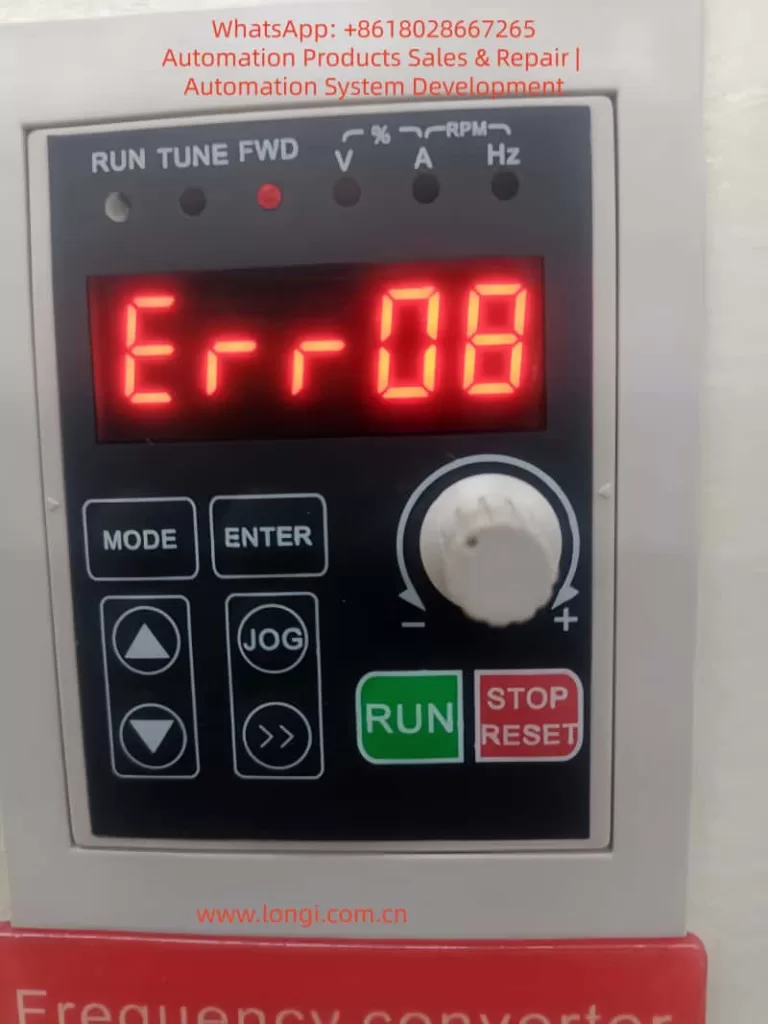
Delixi CDI-EM60 Series Inverter Err08 Fault Code: Comprehensive Guide to Undervoltage Errors, Causes, and Solutions

Introduction to Variable Frequency Drives and the Err08 Fault

Variable frequency drives (VFDs), also known as inverters or adjustable speed drives, are essential components in modern industrial automation systems. They control the speed and torque of AC motors by varying the frequency and voltage of the power supplied to the motor. This technology enables energy savings, precise process control, and extended equipment life in applications ranging from conveyor systems to HVAC units. Delixi, a prominent Chinese manufacturer under the Delixi Group, has established itself as a reliable provider of electrical equipment, including the CDI-EM60 series VFDs. These drives are designed for general-purpose applications, offering robust performance in environments requiring vector control, V/F control, and high overload capacity.

The CDI-EM60 series is particularly popular due to its compact design, user-friendly interface, and cost-effectiveness. However, like any electronic device, VFDs can encounter faults that disrupt operations. Fault codes are diagnostic tools displayed on the VFD’s panel to indicate specific issues, allowing technicians to quickly identify and resolve problems. Among these, the Err08 fault code is a common occurrence in the CDI-EM60 series, signaling an undervoltage condition in the DC bus during operation. This error can lead to unexpected shutdowns, reduced system efficiency, and potential damage if not addressed promptly.

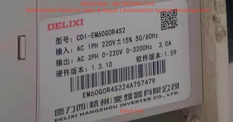
Understanding Err08 is crucial for maintenance personnel, engineers, and system integrators working with Delixi inverters. This fault typically arises from power supply inconsistencies or internal circuit issues, and resolving it requires a systematic approach. In this comprehensive technical article, we delve into the meaning of Err08, its underlying causes, detailed troubleshooting steps, preventive strategies, and related advanced topics. Drawing from the official Delixi CDI-EM60 operation manual and industry best practices, this guide aims to equip readers with the knowledge to handle this fault effectively. Whether you’re dealing with a Delixi CDI-EM60G0R4S2 model or similar variants, this resource provides actionable insights to minimize downtime and optimize performance.

Undervoltage faults like Err08 are not unique to Delixi but are prevalent across VFD brands due to the sensitivity of power electronics to voltage fluctuations. In industrial settings, where power quality can vary due to grid instability or load demands, such errors account for a significant portion of VFD failures. According to industry reports, electrical supply issues contribute to over 30% of VFD downtime, making proactive fault management essential. This article emphasizes a logical, step-by-step methodology to diagnose and fix Err08, ensuring compliance with safety standards and enhancing system reliability. By the end, you’ll have a thorough understanding of how to tackle this issue, potentially saving thousands in repair costs and lost productivity.

ERR08 FUALT

Overview of the Delixi CDI-EM60 Series Variable Frequency Drives

The Delixi CDI-EM60 series represents a line of compact, high-performance VFDs tailored for single-phase and three-phase AC motor control. These drives support input voltages from 220V to 380V, with power ratings ranging from 0.4kW to 7.5kW, making them suitable for small to medium-sized applications. Key features include open-loop vector control (SVC) for precise torque management, V/F control for simple speed regulation, and a built-in PID controller for process automation. The series boasts a 150% overload capacity for 60 seconds and 180% for 3 seconds, allowing it to handle demanding loads like pumps, fans, and compressors.

Structurally, the CDI-EM60 incorporates a modular design with an integrated keypad for parameter setting and monitoring. The display panel shows real-time data such as output frequency, current, voltage, and fault codes in a clear LED format. Input terminals support analog signals (0-10V or 4-20mA), digital inputs for multi-speed control, and relay outputs for alarms. Communication options include RS485 Modbus protocol, enabling integration with PLCs and SCADA systems. The drive’s efficiency exceeds 95%, and it features built-in protections against overcurrent, overvoltage, overload, and short circuits.

In terms of specifications, the CDI-EM60 operates in ambient temperatures from -10°C to 40°C, with IP20 protection against dust and moisture. Models are classified by voltage grades: S1 for single-phase 220V, S2/T2 for three-phase 220V/380V, and T4 for higher voltage applications. For instance, the CDI-EM60G0R4S2 model, as shown in user-provided images, is a 0.4kW single-phase 220V drive with a frequency range of 0-3200Hz and 3.0A output current. This model is commonly used in light industrial machinery, such as woodworking tools or small conveyor belts.

Applications of the CDI-EM60 span various sectors. In manufacturing, it regulates motor speeds for assembly lines, reducing energy consumption by matching output to demand. In water treatment, it controls pump speeds for efficient flow management. HVAC systems benefit from its soft-start capability, preventing mechanical stress on fans and blowers. The series’ reliability is enhanced by features like auto-tuning for motor parameters, which optimizes performance without manual calibration.

However, the CDI-EM60’s advanced electronics make it susceptible to environmental and electrical disturbances. Fault codes, including Err08, serve as the first line of defense, alerting users to anomalies. Proper installation, such as ensuring adequate ventilation and grounding, is vital to maximize the drive’s lifespan, typically rated at over 10 years with regular maintenance. By understanding the series’ capabilities, users can better contextualize faults like Err08 and implement targeted solutions.

CDI-EM60G0R4S2

Understanding Fault Codes in Delixi VFDs

Fault codes in Delixi VFDs are alphanumeric indicators that appear on the keypad display when the drive detects an abnormality. These codes are part of a self-diagnostic system that monitors parameters like current, voltage, temperature, and communication status. In the CDI-EM60 series, faults are prefixed with “Err” followed by a two-digit number, such as Err08. The display alternates between the code and related data, with LED indicators for run status, forward/reverse, and units (Hz, A, V).

The fault system categorizes errors into recoverable and non-recoverable types. Recoverable faults, like minor overloads, can be reset via the “STOP/RESET” button or external signals. Non-recoverable ones, such as hardware failures, require power cycling or professional intervention. The manual lists over 40 fault codes, from Err00 (no fault) to Err40 (buffer resistance fault), each with specific triggers and remedies.

When a fault occurs, the VFD halts output to protect the motor and itself, activating relay outputs for external alarms. Users can access fault history through parameters in group P6.0 (e.g., P6.0.00 for the most recent fault), which records the code, frequency, current, bus voltage, and timestamp. This data is invaluable for root-cause analysis.

General troubleshooting for any fault begins with safety: disconnect power, wait for capacitor discharge (typically 5-10 minutes), and use insulated tools. Consult the manual for code-specific advice, and avoid repeated resets without addressing the cause, as this can exacerbate damage. For Err08, the focus is on voltage-related parameters, but understanding the broader system helps differentiate it from similar codes like Err04 (overvoltage at constant speed).

Detailed Explanation of the Err08 Fault Code

The Err08 fault code in the Delixi CDI-EM60 series indicates an undervoltage condition in the main DC bus circuit during operation. This means the DC voltage, which is rectified from the AC input and used to generate the output waveform, has dropped below a predefined threshold. The VFD continuously monitors the bus voltage via internal sensors, and if it falls too low, the drive triggers Err08 to prevent unstable operation or component failure.

Detection thresholds vary by model grade:

  • S1 series (single-phase 220V): 100V DC
  • S2/T2 series (three-phase 220V/380V): 200V DC
  • T4 series (higher voltage): 350V DC

For example, in the CDI-EM60G0R4S2 (S2 grade), Err08 activates if the bus voltage dips below 200V. This threshold accounts for normal fluctuations but flags significant drops that could impair inverter performance.

Undervoltage differs from overvoltage faults (Err04-Err06) in that it stems from insufficient power supply rather than excess. It typically occurs during running states, not startup, distinguishing it from power-on issues. If ignored, Err08 can lead to motor stalling, increased current draw, or harmonic distortions, potentially triggering secondary faults like Err01 (overcurrent).

Technically, the DC bus voltage is derived from the rectifier bridge, which converts AC to DC, smoothed by capacitors. Nominal bus voltage for a 220V input is around 310V DC (√2 * 220V), and for 380V, it’s about 537V DC. A drop below threshold might result from input voltage sags, where the peak AC doesn’t suffice to maintain the DC level. The VFD’s control algorithm relies on stable DC for PWM (pulse-width modulation) output, so undervoltage disrupts this, causing the fault.

In the context of the CDI-EM60, Err08 is logged in P6.0 parameters, allowing review of conditions at fault time. This code is recoverable after correction, but frequent occurrences signal systemic issues.

Common Causes of Err08 Undervoltage Fault

Err08 in Delixi CDI-EM60 VFDs arises from multiple factors affecting the power supply chain. Understanding these causes requires knowledge of electrical principles, as undervoltage impacts the rectifier and DC link.

  1. Poor Power Supply Connections: Loose or corroded terminals at the input (R, S, T) can increase resistance, causing voltage drops. For instance, a 0.1Ω resistance at 10A current drops 1V, but cumulative effects can push below threshold. Oxidation from humidity or vibration loosens screws, common in industrial environments.
  2. Input Voltage Outside Specified Range: The CDI-EM60 requires stable AC input (e.g., 220V ±15% for S2 models). Grid fluctuations, brownouts, or long cable runs (voltage drop = I²R) can reduce effective voltage. In rural or overloaded grids, peaks might not reach required levels, especially under heavy load.
  3. Momentary Power Interruptions: Brief outages (milliseconds to seconds) discharge DC capacitors without recharge, dropping bus voltage. This is prevalent in areas with unstable utilities or during switching of backup generators. The VFD’s ride-through capability is limited; if interruption exceeds hold-up time (typically 10-20ms), Err08 triggers.
  4. Abnormal Bus Voltage Display or Sensor Issues: Faulty internal voltage sensors or display circuits can misreport values, falsely triggering Err08. Though rare, EMI (electromagnetic interference) from nearby equipment can corrupt readings.
  5. Faulty Charging Resistor or Bridge Rectifier: The pre-charge circuit uses a resistor to limit inrush current to capacitors. If damaged (e.g., open circuit from overheating), it prevents proper charging. The rectifier bridge, converting AC to DC, might have diode failures due to surges, leading to incomplete rectification and low DC output.
  6. Capacitor Degradation: Electrolytic capacitors in the DC link age over time, losing capacitance and increasing ripple. This amplifies voltage dips under load. High temperatures accelerate degradation; for every 10°C rise above 40°C, lifespan halves.
  7. External Factors like Contactor Issues: If an input contactor chatters or fails to close fully, it interrupts power flow. In systems with multiple VFDs, shared bus issues or regenerative loads can indirectly cause undervoltage.
  8. Overloaded or Mismatched Power Supply: If the upstream transformer or generator is undersized, starting large loads draws excessive current, sagging voltage.

These causes interplay; for example, poor wiring exacerbates grid fluctuations. Diagnostic tools like oscilloscopes reveal waveforms, showing if it’s AC side (sinusoidal distortion) or DC side (excessive ripple).

Step-by-Step Troubleshooting Procedure for Err08

Troubleshooting Err08 requires a methodical, safety-first approach. Always follow lockout-tagout procedures, wear PPE, and use calibrated tools like digital multimeters (DMMs) and clamp meters.

Step 1: Initial Assessment and Fault Reset

  • Note the display: Confirm Err08 and record parameters (P6.0.00-P6.0.02) for frequency, current, bus voltage at fault.
  • Press STOP/RESET to attempt reset. If it clears but recurs, proceed; if not, power cycle after 5 minutes.
  • Check environmental conditions: Ensure ambient temperature <40°C, no dust buildup on vents.

Step 2: Verify Input Power Supply

  • Measure AC input voltage at terminals R, S, T with DMM (AC mode). For 220V models, it should be 187-253V; for 380V, 323-437V.
  • Check phase balance: Voltage between phases <3% difference. Use a power quality analyzer for harmonics (THD <5%).
  • Inspect upstream: Test at the source (panel or transformer) to identify drops from cabling (calculate expected drop using wire gauge and length).

Step 3: Inspect Wiring and Connections

  • Visually check terminals for looseness, corrosion, or burn marks. Torque screws to manual specs (e.g., 1.2Nm for M4 terminals).
  • Use continuity test on DMM to ensure no breaks in cables. Measure resistance (<0.1Ω per phase).
  • Ground check: Verify PE terminal continuity to earth (<10Ω).

Step 4: Monitor DC Bus Voltage

  • With power off, discharge capacitors (use resistor across + and -). Power on in no-load mode.
  • Access bus voltage via parameter (e.g., d0.03 in monitoring group) or measure directly at P+ and P- (DC mode on DMM). Nominal: ~1.414 * AC RMS. If < threshold (e.g., 200V for S2), fault confirmed.
  • Run at low frequency (10Hz) and observe for dips under load.

Step 5: Test Internal Components

  • Check rectifier: With power off, test diodes in bridge (forward bias ~0.3-0.7V, reverse infinite). Replace if faulty.
  • Inspect charging resistor: Measure resistance (typically 50-100Ω); if open or shorted, replace.
  • Capacitor test: Use capacitance meter; values should match rating (e.g., 470µF). Look for bulging or leakage.

Step 6: Advanced Diagnostics

  • Simulate conditions: Use a variac to vary input voltage and observe threshold.
  • Check for interruptions: Install a voltage logger to capture transients.
  • Parameter review: Ensure P0.0.03 (input voltage grade) matches hardware; adjust undervoltage protection if customizable (though fixed in CDI-EM60).

Step 7: Re-test and Verify

  • After fixes, run in jog mode (low speed), then full operation. Monitor for 30 minutes.
  • If persistent, consult Delixi support with fault logs.

This procedure typically resolves 80% of cases; complex issues may require oscilloscope analysis for ripple or EMI.

Preventive Maintenance to Avoid Err08 and Similar Faults

Prevention is key to avoiding Err08 in Delixi CDI-EM60 VFDs. Implement a quarterly maintenance schedule:

  • Power Quality Management: Install surge protectors and voltage stabilizers. Use UPS for critical applications to handle interruptions.
  • Wiring Best Practices: Use shielded cables, proper gauges (e.g., 2.5mm² for 0.4kW), and regular inspections.
  • Environmental Controls: Ensure ventilation (min. 100mm clearance), clean filters, and control humidity (<90% RH).
  • Component Monitoring: Track capacitor health via ESR meters; replace every 5-7 years.
  • Parameter Optimization: Set auto-restart after faults (P6.1.03) but limit attempts to avoid cycling.
  • Training and Documentation: Train staff on manual procedures; keep logs of voltage trends.

These measures reduce fault incidence by up to 50%.

Advanced Topics: Parameter Settings and System Integration

In advanced setups, Err08 relates to group P6 parameters. P6.1.00 enables phase loss protection, which can indirectly prevent voltage issues. For PLC integration, use Modbus to read fault registers (address 0x8000 for current fault). Adjust ride-through via P3.1.00 (timing functions) to extend tolerance. In vector mode, tune P1.0.00 (motor parameters) to minimize load-induced dips.

Case Studies and Real-World Examples

Case 1: In a textile factory, a CDI-EM60 drove a spindle motor. Err08 occurred intermittently due to grid sags. Solution: Installed a voltage regulator, resolving issues.

Case 2: A pump station saw Err08 from loose terminals after vibration. Tightening and adding lock washers fixed it.

Case 3: Degraded capacitors in an old unit caused chronic Err08; replacement restored operation.

Conclusion

Err08 in the Delixi CDI-EM60 series signals undervoltage, a preventable fault with proper diagnostics. By following this guide, users can resolve issues efficiently, ensuring reliable VFD performance. Always prioritize safety and consult experts for complex repairs. With proactive maintenance, these drives deliver long-term value in industrial applications.

Posted on

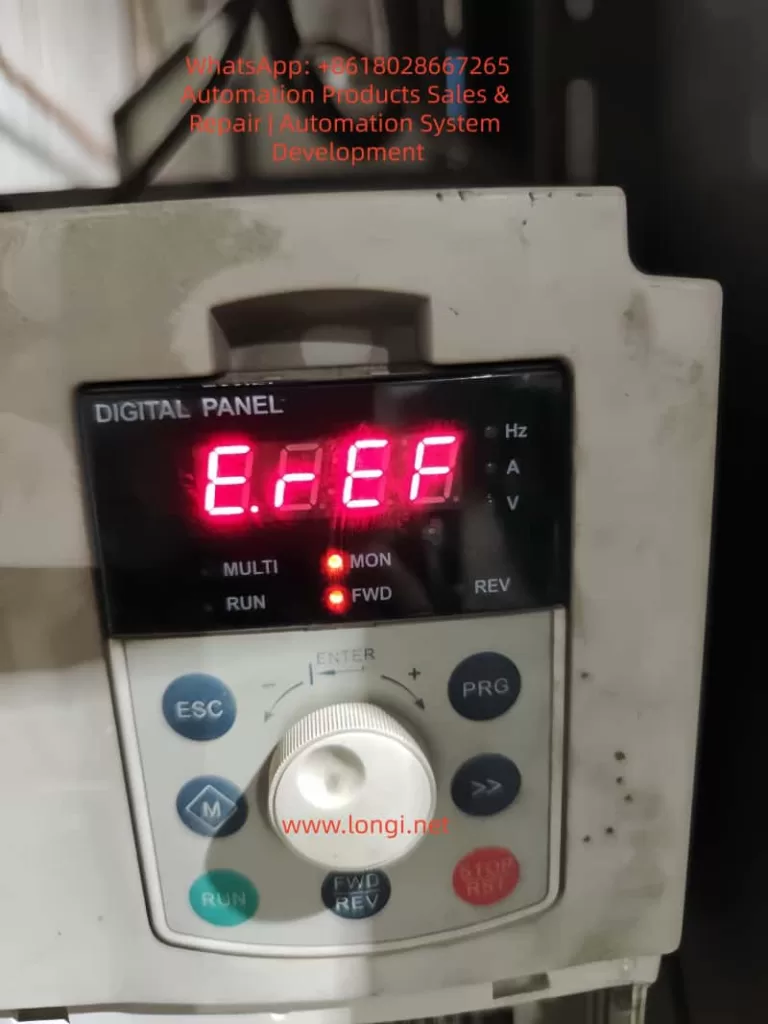
Deep Dive into E.rEF Fault and LOC1 Keypad Lock on Blue Sea Huateng V5-H Inverters: A Practical Troubleshooting Guide

Introduction

The Blue Sea Huateng V5-H series of high-performance vector control inverters is widely used in industrial applications such as water pumps, fans, conveyors, and machine tools due to its high precision and reliability. However, during long-term operation, two specific issues frequently challenge maintenance personnel: the E.rEF (Reference Comparison Abnormality) fault and the LOC1 (Keypad Lock) state.

The E.rEF fault causes the inverter to shut down immediately, while LOC1 locks the operation panel, preventing parameter access and severely impacting production efficiency. This article combines the Blue Sea Huateng V5-H User Manual, practical maintenance case studies, and electronic circuit principles to provide an in-depth analysis of the causes, troubleshooting procedures, and solutions for these two issues.


E.REF fault

Chapter 1: The Nature and Core Causes of the E.rEF Fault

According to the Blue Sea Huateng V5-H High-Performance Vector Control Inverter User Manual (hereinafter referred to as “the Manual”), the E.rEF fault code corresponds to “Reference Comparison Abnormality.” This is a hardware-level fault that requires the inverter to be stopped for inspection.

1.1 Causes Defined in the Manual

The manual explicitly lists three core causes for E.rEF (ranked by probability):

  1. Internal Switching Power Supply Abnormality (approx. 50%): Unstable or missing reference voltage (5V, 15V) causes the control circuit’s reference signal to be incorrect.
  2. Signal Sampling/Comparison Circuit Abnormality (approx. 30%): Errors in current/voltage sampling signals, or damage to the comparison circuit (op-amps, reference sources).
  3. Internal Connector Looseness (approx. 20%): Loose wiring between the control board, power board, and drive board causes signal transmission interruption.

1.2 Fault Logic Chain Analysis

The control core of the inverter is the CPU (e.g., ARM or DSP). Its operation relies on a stable reference voltage (e.g., 5V for CPU power supply, 2.5V as a reference for the comparison circuit) and accurate sampling signals (e.g., motor current, DC bus voltage).

When the reference voltage is abnormal, sampling signals are “misjudged.” For example, if the 5V reference drops to 3V, a 1V current sampling signal will be interpreted by the CPU as 1.67V (1V/3V×5V). If this exceeds the threshold, the E.rEF protection mechanism is triggered.


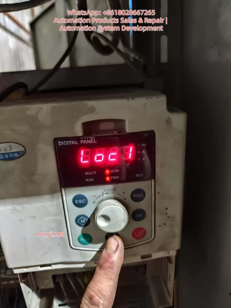
LOC1 of VT&T Inverter

Chapter 2: Step-by-Step Troubleshooting for E.rEF (Simple to Complex)

Troubleshooting E.rEF must follow the principle of “External before Internal, Simple before Complex” to avoid secondary damage from blind disassembly.

2.1 Step 1: Power-Off Internal Connection Check (Most Common Cause)

Scenario: Long-term vibration (pumps, fans) or humid environments cause internal wiring to loosen or oxidize.
Tools: Screwdriver, 95% Alcohol, Tweezers.
Procedure:

  1. Power Off & Discharge: Disconnect input power (L1/L2/L3) and wait 5 minutes. Use a multimeter to verify the voltage between P+ and N- is <36V.
  2. Open Cover: Remove screws (check for hidden screws under heat sinks).
  3. Inspect Ribbon Cables: Locate connectors (CN1, CN2, CN3) between the Control Board, Power Board, and Drive Board.
    • Gently reseat ribbon cables to ensure they are not loose.
    • If gold fingers are oxidized (blackened), clean with an alcohol swab.
  4. Secure Cables: Use cable ties to fix ribbons to the board to prevent re-loosening due to vibration.

2.2 Step 2: Power-On Switching Power Supply Test (Critical Step)

If reseating cables fails, test the Power Board output voltages. Reference voltage anomalies are the core cause of E.rEF.
Tools: Multimeter (FLUKE 15B+ recommended), Oscilloscope (optional for ripple).

Test Points & Normal Ranges (380V Input Example):

Test PointNormal RangeConsequence of Abnormality
+5V / GND4.8V – 5.2VCPU & Sampling Circuit Reference Error
+15V / GND14V – 16VOp-Amp & Comparison Circuit Failure
+24V / GND22V – 26VRelay & Fan Failure
DC Bus (P+/N-)513V – 567VRectifier/Filter Capacitor Failure

Operation:

  1. Power on (motor disconnected). Set multimeter to DC Voltage.
  2. Measure outputs. If 5V is abnormal (<4.5V or >5.5V), the 5V switching circuit has failed.
    • Check: Filter capacitors (bulging/leaking?), Switching MOSFET (short circuit?), PWM Controller (e.g., UC3842).
  3. If all outputs are 0V, the main rectifier circuit has failed (rectifier bridge shorted, main capacitor blown).

2.3 Step 3: Signal Sampling Circuit Inspection

If power supply is normal, check the sampling circuits.

2.3.1 Current Sampling (Hall Sensor)

Principle: Hall sensor outputs voltage proportional to motor current (e.g., 10A = 1V).
Detection:

  1. Disconnect motor wires.
  2. Locate the Hall sensor on the drive board.
  3. Measure output voltage (OUT to GND):
    • Static: 0V (Normal).
    • Dynamic: 0-5V depending on load.
  4. Fault: 0V (Sensor dead) or 5V (Sampling resistor open). Replace the Hall sensor or the 0.1Ω/5W sampling resistor.

2.3.2 Voltage Sampling (DC Bus)

Principle: High voltage is divided by resistors (e.g., 100kΩ and 10kΩ) to a low voltage for the CPU.
Detection:

  1. Measure voltage across the lower divider resistor (R2).
  2. Fault: 0V (R1 open) or Abnormally High (R2 shorted). Replace the respective resistor.

2.4 Step 4: Comparison Circuit & Reference Source (Advanced)

If sampling is normal, check the comparison circuit (Op-Amps like LM358).
Tools: Oscilloscope.
Detection:

  1. Reference Source (TL431): Measure cathode voltage. Should be 2.5V ±1%. If not, replace TL431.
  2. Op-Amp (LM358):
    • Input: IN+ (Sampling Signal), IN- (2.5V Reference).
    • Output: High (5V) if Signal > Reference; Low (0V) if Signal < Reference.
    • Fault: If inputs are correct but output is stuck Low/High, replace the Op-Amp.

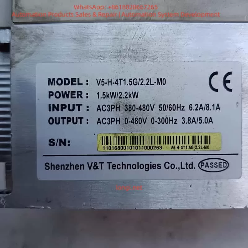
V5-H-4T1.5G

Chapter 3: LOC1 Keypad Lock: Causes and Unlocking

LOC1 indicates the Keypad Lock State (Parameter P2.00 = 1). All keys except RUN/STOP are disabled to prevent accidental parameter changes.

3.1 Trigger Scenarios

  1. Accidental Operation: Pressing the specific key combination.
  2. Parameter Setting: P2.00 was mistakenly set to 1.
  3. Panel Fault: Keypad short circuit.

3.2 Standard Unlocking Method (Per Manual)

According to Manual Section 4.6, the LOC1 Unlock Combination is:
Simultaneously press 「ESC」 + 「Jog Wheel Counter-Clockwise」 + 「◄ Key」
(Note: If no ◄ key, try PRG or M key)

Step-by-Step Operation:

  1. Power on (Display shows LOC1).
  2. Hold ESC (top left) with left thumb.
  3. Hold the Jog Wheel with right index finger and rotate Counter-Clockwise (towards “-“).
  4. Hold the ◄ Key (left direction key) with right middle finger. If unavailable, try PRG.
  5. Hold all three for 3-5 seconds until the display changes from “LOC1” to “8888” or operation parameters.
  6. Release. Verify keys are responsive.

3.3 Disabling the Lock (Modifying P2.00)

After unlocking, change P2.00 to 0 to prevent recurrence.

  1. Press PRG to enter the menu.
  2. Rotate to find P2.00 (Keypad Lock Setting).
  3. Press ENTER, change value from 1 to 0, and confirm.

Chapter 4: Case Study: V5-H-4T1.5G Maintenance Process

4.1 Fault Phenomenon

A V5-H-4T1.5G inverter (1.5kW, 380V) driving a conveyor belt tripped with E.rEF. The panel showed LOC1, preventing menu access.

4.2 Troubleshooting Process

  1. Step 1: Reseated CN1 ribbon cable between Control and Power boards. Fault persisted.
  2. Step 2: Measured power supply. 5V was only 3.2V (Normal: 4.8-5.2V). 15V and 24V were normal.
  3. Step 3: Inspected Power Board. Found the 470μF/25V filter capacitor for the 5V rail was bulging and leaking.
  4. Step 4: Replaced the capacitor. Power-on test showed 5V = 5.1V. E.rEF cleared.
  5. Step 5: Performed unlock: ESC + Counter-Clockwise Rotation + PRG Key for 5 seconds. Display switched to “8888”.
  6. Step 6: Entered menu, changed P2.00 from 1 to 0. LOC1 disappeared.

4.3 Result

The inverter restarted successfully. Running current was 1.1A (Rated: 1.5A). No faults recurred in 3 months of follow-up.


Chapter 5: Preventive Maintenance

5.1 Environmental Maintenance

  • Installation: Ensure good ventilation and dryness (0-40°C, <80% RH). Avoid direct sunlight.
  • Heat Dissipation: Clean dust from heat sinks every 3 months using compressed air. Add cooling fans if ambient temp > 30°C.

5.2 Connection Checks

  • Internal: Check ribbon cables (CN1, CN2) every 6 months. Secure with cable ties.
  • External: Tighten power (L1/L2/L3) and motor (U/V/W) terminals regularly.

5.3 Parameter Management

  • P2.00 Setting: Avoid setting P2.00=1 unless necessary.
  • Backup: Backup parameters using the panel or Blue Sea Huateng software (V5-H Programmer).

5.4 Periodic Testing

  • Power Supply: Test 5V/15V/24V outputs annually.
  • Sampling Circuit: Test Hall sensors and resistors biennially.

Chapter 6: Frequently Asked Questions (Q&A)

Q1: Can E.rEF be cleared by resetting?
A: No. E.rEF is a hardware fault. You must repair the underlying issue (power supply, sampling, etc.) before it clears. Pressing STOP/RST will not work.

Q2: I can’t enter the menu due to LOC1. What should I do?
A: You must use the unlock key combination defined in the manual. If it fails, the keypad panel may be faulty and need replacement.

Q3: Can I repair the power board myself if 5V is abnormal?
A: If you have electronics experience, check common failure points: filter capacitors, switching MOSFETs, and PWM controllers (UC3842). If inexperienced, replacing the entire power board is safer and often more cost-effective.

Q4: How do I quickly diagnose a sampling circuit fault?
A: Use a multimeter to measure the sampling voltage:

  • If voltage is 0V or full scale (5V), the sampling circuit (Hall sensor/resistor) is dead.
  • If voltage is normal but E.rEF persists, the comparison circuit (Op-Amp/Reference) is faulty.

Conclusion

The E.rEF fault and LOC1 lock on Blue Sea Huateng V5-H inverters are common but manageable. By mastering the “Simple to Complex” troubleshooting logic—checking ribbons first, then power supply, then sampling/comparison circuits—and proficiently using the manual unlock combination, technicians can restore equipment quickly.

Key Takeaways:

  • E.rEF is usually caused by unstable reference voltage or sampling errors. Prioritize checking the power board and internal connections.
  • LOC1 is solved by the specific key combination. Always set P2.00 = 0 after unlocking to prevent recurrence.
  • Preventive maintenance (dust cleaning, cable tightening, voltage checks) is the best way to avoid downtime.
Posted on

User Manual for KCLY KOC-G6/P6 Series Inverters

The KCLY (Kechuang Liyuan) KOC-G6/P6 series high-performance vector control inverters adopt sensorless vector control technology. They feature a starting torque of 150% rated torque at 0.35Hz and a speed stability accuracy of ±0.5%. These inverters are widely used in CNC machine tools, wire drawing machines, textile equipment, injection molding machines, hoisting equipment, and other industries. This guide is based on the official user manual and provides detailed instructions on panel operation, external terminal control, potentiometer speed regulation, fault handling, and typical application cases to help users master the equipment quickly and achieve efficient and stable operation.


Front view image of KCLY KOC-G6 frequency converter

1. Operation Panel Introduction

The KOC-G6/P6 series comes standard with a digital operation panel (keypad) featuring an ergonomic key layout. It supports parameter setting, operation monitoring, fault reset, and other functions. The panel mainly includes a digital display area, indicators, and keys.

Indicator Light Functions

  • Hz/A/V: Frequency/Current/Voltage display (flashing indicates running).
  • RUN: Running status (solid on for running, flashing for decelerating/stopping).
  • DIR: Forward/Reverse indication (solid on for reverse).
  • LOCAL: Local control (lights up when controlled by the panel).
  • TRIP: Fault alarm.

Key Functions

  • PRG/ESC: Enter/Exit menu, clear alarms.
  • DATA/ENTER: Confirm modifications, enter sub-menu.
  • Shift Key: Switch editing digits or monitor parameters.
  • UP/DOWN: Increase/decrease values or function codes.
  • M Key (Multi-function key, defined by FU.114): 0-Invalid; 1-Forward/Reverse toggle; 2-Jog operation.
  • RUN: Start (valid in keypad control mode).
  • STOP/RESET: Stop or reset faults (can be set to be valid in terminal/communication mode via FU.115).

Panel Operation Procedure

  1. After power-on, the set frequency is displayed (default 50.00Hz).
  2. Press PRG to enter the primary menu (mainly FU function group).
  3. Use UP/DOWN to select the function code, press DATA to enter edit mode, use UP/DOWN to modify the value, press DATA to confirm, and press PRG to exit.
  4. Quick Monitoring Mode: Press PRG to cycle through 13 operating parameters (set frequency, output frequency, current, voltage, speed, temperature, etc.).

How to Set and Cancel Password (Parameter Access Restriction)

KOC-G6/P6 provides write protection for function codes to achieve “password” level access control:

  • Set Access Restriction: Enter FU.200 and set it to 1 (Valid). At this point, no parameters can be modified except for basic monitoring, protecting intellectual property and site settings.
  • Cancel Password/Restriction: Change FU.200 to 0 (Invalid) to restore modifiable status.
  • Operation Suggestion: Set to 0 during initial debugging, and set to 1 after debugging is complete. Combine with FU.199 initialization function for hierarchical management.

How to Restore Factory Default Parameters

  • Enter function code FU.199.
  • Set it to 1 (Initialize to factory defaults) and press DATA to confirm.
  • The inverter automatically restores all FU group parameters (motor parameters, control mode, terminal definitions, etc.) to factory settings.
  • Note: Back up key parameters before operation (using upper computer or manual recording). FU.199=2 can clear fault records separately.

After restoration, motor auto-tuning (FU.060=1 or 2) and basic parameter settings are required.


KOC-G6/P6-7.5/11T4

2. External Terminal Forward/Reverse Control and Potentiometer Frequency Setting

The KOC-G6/P6 supports flexible external control, suitable for automated production lines.

External Terminal Forward/Reverse Control Wiring and Parameter Settings

Wiring Key Points (Control Circuit Terminals)

  • +24V and COM: Provide control power.
  • X1 (or X2) connect to forward button/contact (FWD).
  • X2 (or X1) connect to reverse button/contact (REV).
  • COM common terminal (Note: No additional enable is required for two-wire system).
  • Grounding terminal E must be reliably grounded.

Recommended Parameter Settings (FU Group)

  • FU.002 (Operation Command Source) = 1 (Analog Terminal Control).
  • FU.088 (Terminal Control Mode) = 0 (Two-wire Type 1, most common: X1 closed for forward, X2 closed for reverse, both closed to stop); or =1 (Two-wire Type 2: X1 forward, X2 reverse); Three-wire type (2 or 3) requires an additional enable terminal.
  • FU.080 (X1 Function) = 1 (Forward Run).
  • FU.081 (X2 Function) = 2 (Reverse Run).
  • FU.024 (Rotation Direction Control) = 0 (Default direction).
  • FU.048 (Forward/Reverse Dead Time) = 0.5s (Prevents impact from frequent switching).

Operation: External buttons control start/stop and direction, with priority higher than the keypad. Supports multi-function input expansion (X3-X8 can be set to jog, reset, etc.).

External Potentiometer Frequency Setting

Wiring

  • One end of the external potentiometer (10kΩ recommended) connects to +10V, the other end to GND, and the middle tap to AI1 (voltage type 0-10V).
  • For current type, switch the AI1 jumper to I position (0-20mA), but voltage type is more common.

Parameter Settings

  • FU.002 = 0 (Keypad control) or 1 (Terminal control), depending on the command source.
  • FU.003 (Frequency Instruction Selection A) = 2 (AI1).
  • FU.089~FU.092: AI1 curve calibration (default 0-10V corresponds to 0-50Hz, max/min values can be adjusted).
  • FU.093 (AI1 Filter Time) = 0.5s (Anti-interference).
  • FU.005 (Frequency Source Combination) = 0 (Pure AI1) or superimposed with other sources (A+B, etc.).

Speed Regulation Effect: Rotating the potentiometer achieves smooth speed regulation from 0 to max frequency. Combined with vector control, it achieves high torque at low frequency. The panel potentiometer (FU.003=0) can be used as a backup.

Note: Analog input requires shielded cable, length <50m; ensure jumpers are correct (AI1 default is voltage).


3. Fault Codes and Troubleshooting

KOC-G6/P6 faults are queried via the TRIP light, panel display code, and FE group records. Common fault codes (based on series characteristics) and solutions:

Fault CodeMeaningCauseSolution
OCxOvercurrentExcessive current during acceleration/operation (heavy load, short acceleration time, parameter mismatch)Extend FU.014/015 acceleration time; check motor auto-tuning (FU.060); reduce carrier frequency (FU.022); check for mechanical jamming.
OUxOvervoltageHigh DC bus voltage during deceleration (short deceleration time, high inertia)Extend deceleration time; add braking resistor (PB terminals); enable FU.052 automatic voltage stabilization.
LUUndervoltageLow input voltage or momentary power lossCheck power supply; enable FU.040 restart after momentary power loss.
OHOverheatInverter or motor overheatingImprove heat dissipation; check air duct; reduce carrier frequency; set FU.117 motor overload factor.
EFExternal FaultMulti-function input triggeredCheck external signals, clear after reset.
OthersShort Circuit/Ground/Parameter ErrorSC, GF, Parameter Error, etc.Power off and check insulation; verify parameters; contact manufacturer for serious faults.

General Troubleshooting Steps

  1. Record the fault code and operating parameters (check FE group).
  2. Restart after powering off for 10 minutes; check wiring and insulation.
  3. Perform motor parameter auto-tuning.
  4. Enable FU.125 automatic fault reset (0-3 times).
  5. For serious faults, contact the manufacturer (400-788-9588).

Regular Maintenance: Check capacitors and fans; record maximum temperature.


4. Typical Application Cases

Case 1: CNC Machine Tool Spindle Control

A precision machining center uses a 7.5kW KOC-G6. Set open-loop vector control (FU.001=1), AI1 potentiometer speed regulation (180% torque at 0.35Hz), and S-curve acceleration/deceleration. Achieves low-speed precision machining with dynamic response <20ms and speed stability ±0.3%. Replaces imported brands with a 30% cost reduction.

Case 2: Wire Drawing Machine Tension Control

A medium wire drawing machine uses an 11kW P6 model. External terminal forward/reverse + multi-speed (FU.128-135) combined with PID closed-loop (FU.148=1). Operates without a dancer arm, with stable high torque at low frequency. The power-off restart function ensures continuous production with significant energy savings.

Case 3: Injection Molding Machine Energy-Saving Retrofit

A 22kW G6 with injection molding dedicated expansion card. Receives molding machine signals to automatically distribute flow and pressure. Trip-free design (200% overload capacity for 0.5s) and green output reduce interference. Measured energy saving of 20-35%; no parameter changes needed when replacing molds.

Case 4: Textile Frequency Swing and Constant Linear Speed

Chemical fiber equipment uses 15kW. Enables frequency swing function, anti-overlap, and fixed-length counting (internal counter). Constant linear speed mode prevents loose inside/tight outside. 10-hour long acceleration/deceleration time adapts to roving frames, improving yarn quality.

Case 5: Hoisting Equipment Four-Quadrant Operation

A 5.5kW crane uses torque monitoring + four-quadrant operation to prevent slipping. Speed tracking function (FU.025=2) enables recovery after momentary power loss, ensuring safety with braking unit.


5. Summary and Precautions

The KOC-G6/P6 series is renowned for high reliability (independent air duct, three-proof design, comprehensive protection) and flexibility. Correctly setting panel/terminal parameters and performing motor auto-tuning are key to stable operation. Recommendations:

  • Perform insulation check and motor auto-tuning before first use.
  • Back up important parameters.
  • Regularly check heat dissipation and wiring.
  • Consult manufacturer technical support for complex applications.
Posted on

In-Depth Analysis and Troubleshooting Guide for ERR12 Fault in Anda VCD-2000 Series Inverter: Systematic Diagnosis and Prevention of Inverter Module Protection

Introduction

The Anda (Shanghai Weilang Electric) VCD-2000 series inverter, as a domestic mid-to-high-end vector control inverter, is widely used in industrial automation due to its stable performance, rich functions, and cost-effectiveness. This series supports full vector control (VEC.1 mode) and is suitable for machine tools, fans and pumps, textiles, constant pressure water supply, and other applications. However, in actual operation, the ERR12 (or displayed as E-12) fault code occurs frequently, becoming one of the most common alarms for users.

ERR12 is essentially Inverter Module Protection. Upon detecting an abnormality in the IGBT module, the inverter immediately blocks the PWM output and trips. If handled improperly, this fault can cause equipment downtime, production interruptions, or even damage to power devices. This article takes the VCD-2000 series as the object, combining the official manual fault diagnosis table, vector control parameter group (PA group), and field actual cases, to systematically sort out the causes, diagnosis process, exclusion methods, and prevention strategies of ERR12. The content is based on principle analysis, parameter optimization, and engineering practice, aiming to help electrical engineers and technicians quickly locate and completely solve the fault.


ERR 12

The Essential Meaning of ERR12 Fault

In the VCD-2000 series, ERR12 corresponds to the E-12 code in Chapter 7 “Fault Diagnosis and Handling” of the manual, and the fault type is clearly defined as Inverter Module Protection. The inverter monitors the operating status of the inverter bridge (IGBT module) in real-time through built-in current sensors, voltage detection circuits, and temperature sensors. Once any of the following abnormalities is detected, protection is triggered immediately:

  • Instantaneous overcurrent (output current peak exceeds the hardware protection threshold, usually 200%-300% of the rated current)
  • Module overheating
  • Drive undervoltage or abnormality
  • Output short circuit / ground fault
  • Control board communication or logic abnormality

Different from general overcurrent protection (E-01/E-02), ERR12 focuses more on the safety of the power module itself and belongs to the highest priority protection at the hardware level. After triggering, the inverter panel displays “Err 12”, and the relay outputs a fault signal. Manual reset (STOP key or external reset terminal) is required to restart.

The design purpose of this protection mechanism is to prevent IGBT from being damaged due to overstress. As the core power device of the inverter, IGBT works in a high-frequency switching state (typical carrier frequency 2-15kHz). Any current spike, voltage spike, or poor heat dissipation can cause breakdown or thermal failure.


Detailed Explanation of Possible Causes of ERR12

According to the VCD-2000 manual fault code table, the main causes of ERR12 can be summarized into 8 categories, each with a deep mechanism:

  1. Instantaneous overcurrent of the inverter
    The most common cause (accounting for about 40%). When the motor starts, the load changes suddenly, or during heavy-load acceleration, the output current peak exceeds the protection threshold. In vector control mode, if the motor parameter self-learning is inaccurate (PA.00 not executed or PA.01~PA.11 settings are wrong), it will cause excessive current loop regulation and generate spike current.
    Typical scenarios: Direct start of heavy-load fans/pumps, belt slipping then suddenly gripping, winder tension mutation.
  2. Output three-phase short circuit or ground short circuit
    Aging of cable insulation, decrease of motor winding insulation to ground, water ingress in the junction box, or burn-off of contactor contacts cause phase-to-phase or ground short circuits. If the UV/W phases on the output side of the inverter are short-circuited simultaneously, or the ground resistance of a single phase is below the specified value (usually <5MΩ), it will trigger the fault.
  3. Air duct blockage or fan damage
    In environments with high dust (common in textile, mining, injection molding workshops), the heat dissipation duct is blocked by lint or metal chips, causing the IGBT module junction temperature to rise rapidly. Fan bearing wear, blade breakage, or capacitor aging will also result in insufficient air volume. The manual clearly states that derating is required when the ambient temperature exceeds 40°C.
  4. Excessive ambient temperature
    Temperature inside the control cabinet >45°C, air inlet blocked, or poor sealing of the cabinet body leading to heat accumulation. High temperatures in summer combined with the inverter’s own heat generation (efficiency is about 96%-98%, a 1.5kW model generates about 60-80W of heat at full load) can easily exceed the standard.
  5. Loose control board wiring or plugs
    Transportation vibration and thermal expansion/contraction during long-term operation cause poor contact between the flat cables and drive optocoupler plugs connecting the control board and power board. The VCD-2000 uses a split structure; if the pins connecting the power board and control board loosen, the drive signal will be distorted, causing IGBT mis-conduction and direct short circuit.
  6. Abnormal current waveform caused by output phase loss, etc.
    One phase of the output cable is broken, one phase of the motor winding is open, or the contactor has poor contact in one phase, causing severe imbalance in the three-phase current. Vector control has extremely high requirements for current waveform; an imbalance >10% can trigger protection.
  7. Auxiliary power supply damage, drive voltage undervoltage
    The internal switching power supply of the inverter (+15V/-15V/+5V, etc.) ages or is overloaded, causing the IGBT drive voltage to drop below 12V (typical requirement is 15V±10%). At this time, the IGBT operates in the amplification region rather than the saturation region, increasing the on-state voltage drop and heat generation sharply.
  8. Control board abnormality
    CPU crash, EEPROM parameter corruption, or hardware failure (very rare, but possible in aging models). In this case, ERR12 may be falsely reported even without external abnormalities.

VCD2000+A4T0014B

Systematic Fault Diagnosis Process

Following the principle of “safety first, from surface to deep, step-by-step investigation,” the following 10-step diagnosis method is recommended (usually takes 15-60 minutes):

Step 1: Safety Confirmation
Cut off the main power, wait for the DC bus voltage to drop to <36V (measure with a multimeter at P-N terminals), and wear insulating gloves. Hang a “Do Not Energize” warning sign.

Step 2: Initial Reset and Observation
Power on again and observe if the fault reappears immediately. If ERR12 appears immediately after reset, it is mostly permanent hardware damage; if it appears after running for a while, it is mostly an overheating or parameter issue.

Step 3: Check External Wiring

  • Measure the three-phase winding resistance of the motor (balanced three phases, error <2%)
  • Measure the insulation resistance to ground (>5MΩ, use a 500V megohmmeter)
  • Check if the output cable is damaged, bitten by rats, or has oil stains
  • Confirm that the contactor/thermal relay is not stuck

Step 4: Check Cooling System

  • Clean the air duct and filter (blow with compressed air)
  • Feel if the fan is rotating and if there is abnormal noise
  • Measure the ambient temperature and inverter radiator temperature (normal <60°C)

Step 5: Motor Parameter Self-Learning Verification
This is the key for vector control models!

  • Execute PA.00=1 (dynamic self-learning, requires no load) or PA.00=2 (static self-learning)
  • Confirm PA.01~PA.11 match the motor nameplate exactly (especially PA.03 rated current, PA.07/PA.08 stator/rotor resistance)
  • After self-learning, run at no load and observe if the output current stabilizes within 10% of the rated current

Step 6: Current Waveform Detection
Use an oscilloscope or clamp meter (true RMS) to monitor the U/V/W three-phase currents. The normal waveform should be a PWM modulated wave close to a sine wave, with imbalance <5%. Abnormal waveforms (spikes, DC components) directly point to short circuits or phase loss.

Step 7: Drive Voltage Detection
Open the cover (after power off), measure the +15V/-15V voltage on the IGBT driver board. If the deviation is >10%, replace the auxiliary power board.

Step 8: Control Board Plug Check
Gently plug and unplug all flat cables and multi-pin sockets, checking for oxidation or bent pins. Clean contacts with alcohol cotton.

Step 9: Parameter Protection Function Verification

  • Check Group P5 (protection related parameters): overcurrent protection coefficient, carrier frequency (P0.15 is recommended to be reduced to 2-6kHz for heavy loads)
  • Confirm no false alarms (e.g., whether P5.00 overvoltage protection value is set too low)

Step 10: Hardware Replacement Verification
If all above are normal, replace in order: fan → auxiliary power board → IGBT module (requires professional tool crimping) → whole control board.


Targeted Exclusion Methods and Parameter Optimization

1. Handling Overcurrent Faults

  • Extend acceleration time (change P0.11/P0.12 from 10s to 30-60s)
  • Enable torque boost limit (reduce PA.15 appropriately)
  • Switch to V/F control mode for testing (P0.00=0); if no alarm is reported, confirm it is a vector parameter issue
  • Increase inverter capacity for heavy-load applications (recommended sizing margin of 1.2-1.5 times)

2. Handling Short Circuits / Ground Faults

Replace cables, rewind motor windings, or replace the motor. Installing an output reactor (3%-5%) can effectively suppress dv/dt and ground leakage current.

3. Cooling System Optimization

  • Install an air conditioner or exhaust fan in the cabinet to control intake air temperature <35°C
  • Clean the filter regularly (every 3 months)
  • Reduce carrier frequency in high-temperature environments (P0.15=2kHz), which can reduce switching losses by more than 30%

4. Auxiliary Power and Drive Circuit

The auxiliary power board has a high failure rate; it is recommended to replace it preventively every 2-3 years for aging models. Replace drive optocouplers (commonly PC817 or TLP series) in batches after aging.

5. Vector Control Specific Optimization

The PA group parameters of VCD-2000 have a great impact on ERR12:

  • PA.07/PA.08 (stator/rotor resistance): error >10% will cause current loop oscillation
  • PA.12 (torque current overcurrent protection coefficient): recommended to set to 120%-150%
  • PA.13/PA.14 (speed loop PI): increase appropriately in high-response occasions to prevent oscillation
  • After performing complete dynamic self-learning, the running current should be 10%-20% lower than in V/F mode

Typical Field Case Analysis

Case 1: Frequent ERR12 Tripping in a Textile Workshop
Four 7.5kW VCD-2000 units driving winding machines in a chemical fiber factory reported ERR12 2-3 times a week after 3 years of operation. Inspection revealed that lint in the workshop severely blocked the air ducts, and the radiator temperature reached 78°C. After cleaning the air ducts, reducing the carrier frequency to 4kHz, and installing an independent air duct, the fault disappeared completely.
Lesson: The textile industry must perform mandatory maintenance on the cooling system quarterly.

Case 2: ERR12 Immediately at Startup of Injection Molding Machine
A newly installed 1.5kW unit reported ERR12 at startup. Measuring motor parameters revealed that the user directly used nameplate data without performing self-learning. After executing PA.00=2 static self-learning, the current peak dropped from 28A to 11A, and the fault was eliminated.
Note: Vector control must perform parameter self-learning, otherwise the current loop will be out of control.

Case 3: Ground Short Circuit Caused by Water Ingress in Cable
At an outdoor water pump station, ERR12 occurred after the rainy season. A megohmmeter measured U-phase to ground at only 0.8MΩ. After replacing the cable and adding an output reactor + waterproof junction box, the unit ran stably.

Case 4: Control Board Fault in an Aging Model
A 3.7kW unit used for 8 years still reported ERR12 even with a very light load. It was restored after replacing the control board. The cost was about 15% of the original model, which was worthwhile.


Preventive Maintenance and Long-Term Solutions

  1. Daily Inspection (Weekly)
    Observe running current, temperature, and abnormal noise; record fault history (P6 group fault records).
  2. Quarterly Maintenance
    Clean air ducts, tighten all wiring, measure insulation resistance, and check fans.
  3. Annual Professional Maintenance
    Replace wearing parts (fans, electrolytic capacitors, auxiliary power supply), re-perform motor self-learning, and upgrade firmware (if available).
  4. System-Level Protection
    • Install AC reactors + surge suppressors on the input side
    • Install sine wave filters on the output side (mandatory for long cables >50m)
    • Use IP54 or higher protection for control cabinets with independent ventilation
    • Configure bypass contactors for important occasions to ensure “inverter fault does not affect production”
  5. Parameter Backup
    Use VCD-2000 upper computer software or manually record all parameters (especially the PA group) for quick recovery after a fault.

Conclusion

ERR12, as the most common inverter module protection fault in the VCD-2000 series, is essentially the device’s active defense for its own safety. Over 90% of cases can be completely solved through standardized diagnostic procedures, thorough hardware inspection, and targeted parameter optimization. A true expert does not passively repair after a failure occurs, but reduces the failure rate to the lowest through preventive maintenance and system design.

It is recommended that users establish an “Inverter Maintenance File” to record each fault phenomenon, handling process, and parameter modifications, forming an internal corporate knowledge base. As a mature product, the Anda VCD-2000 can achieve 5-8 years of stable operation without major faults as long as it is used according to the manual specifications.

By mastering the diagnostic thinking and optimization methods in this article, you can not only quickly solve ERR12 but also handle other inverter faults by analogy, improving the reliability of the entire automation system.

Posted on

Hitake VFC-1200 Inverter OPE01 KVA SELECTION Fault Detailed Explanation: A One-Stop Solution Guide for O2-04 Parameter Setting Errors

In the field of industrial automation, the Hitake VFC-1200 series inverters are widely used in equipment such as fans, pumps, machine tools, and conveyor lines due to their high-performance vector control, ultra-low noise, and reliable current and torque control characteristics. However, many users often encounter a seemingly simple yet easily project-stalling fault during installation and commissioning – OPE01 KVA SELECTION (capacity selection anomaly). This fault directly prevents the inverter from initializing properly, with the operator stuck on the “OPE01 KVA SELECTION” screen and unable to enter the normal operation mode.

This article provides an in-depth, all-round analysis of the Hitake VFC-1200 OPE01 fault, covering fault phenomena, root causes, complete solution steps, parameter principles, prevention strategies, and advanced debugging techniques. Whether you are an engineer new to the VFC-1200 or an experienced user facing parameter loss issues, this article offers immediately implementable solutions.

OPE01

I. OPE01 KVA SELECTION Fault Phenomena and Hazards

When you press the power switch and the Hitake VFC-1200 operator lights up, the screen directly displays:

OPE01 KVA SELECTION

At the same time, the READY light may be on, but operations such as RUN and STOP are ineffective, and frequency setting or EASY-TUNING or normal operation cannot be carried out. This is not hardware damage but a software-level protection caused by parameter initialization anomalies.

Typical Manifestations

  • Appears immediately upon power-on or right after parameter modification.
  • Even when setting 11-01 to 4 (advanced mode), the O2-04 parameter cannot be found.
  • When attempting EASY-TUNING, it prompts data errors or gets stuck on the capacity selection screen.
  • Some older models may also be accompanied by a slight beep or an unresponsive operator.

Hazard Analysis

  • Directly prevents equipment from being put into production, delaying the project schedule.
  • If forced to run, it may trigger overcurrent and overvoltage protection (OC and OV faults).
  • For systems with multiple inverters in parallel or PID control systems, it can cause the entire control logic to collapse.
  • Users in Vietnam, Southeast Asia, and other regions often misjudge it as a “broken machine” due to language barriers and blindly send it for repair, increasing unnecessary costs.
  • Data statistics: According to Hitake’s official technical support data, OPE01 accounts for about 18% of the faults in the VFC-1200 series, making it the third most common fault after overload (OL) and undervoltage (UV).

II. Root Cause of the Fault: The “Hidden” Mechanism of the O2-04 Capacity Parameter

To completely resolve OPE01, it is essential to first understand the parameter hierarchical design of the Hitake VFC-1200.

1. The Uniqueness of the O2-04 Parameter

Pages 68 (“Simple Parameter Summary Table”) and 84 (“Inverter Fault Instructions and Countermeasures”) of the manual clearly state:

  • O2-04: Inverter horsepower capacity selection (KVA Selection).
  • The factory value is automatically locked according to the model:
    • F2011 (220V 15HP / 11kW): O2-04 = 7
    • F2007 (7.5HP): O2-04 = 5
    • F4015 (440V 20HP): O2-04 = 9

Why can’t the O2-04 parameter be found in the user menu?

This is Hitake’s safety protection mechanism:

  • O2-04 belongs to the “hardware-bound parameter,” directly affecting core calculations such as IGBT module drive current, overload protection thresholds, and carrier frequency upper limits.
  • In the normal user layer (11-01 = 2 or 3), this parameter is hidden to prevent mismodification that could lead to hardware burnout.
  • Only when 11-01 = 4 (ADVANCED LEVEL) can it be indirectly accessed, but modification still requires a factory reset or a specific sequence.

2. The Four Root Causes Triggering OPE01

  • Parameter power loss: Long-term power outages or battery aging cause the internal EEPROM capacity data to be cleared.
  • Illegal parameter writing: Incorrect KVA values are forcibly written through communication modules or third-party software.
  • Inconsistent model labels: After repairing and replacing the main board, the O2-04 is not synchronized (most common in second-hand equipment).
  • EASY-TUNING interruption: The automatic tuning process is suddenly interrupted by a power outage, and the capacity table is not written back.

Comparative Analysis: Compared with other brands (such as ABB ACS580 and Siemens G120), Hitake’s O2-04 design is more “hidden,” but once the pattern is mastered, the resolution efficiency is extremely high.

III. Complete Solution Tutorial for the Hitake VFC-1200 OPE01 Fault (Practical Steps)

Preparation (5 minutes)

  • Confirm the nameplate: The MODEL must be VFC-1200-F2011 (220V 15HP).
  • Completely separate the motor from the load (safety first).
  • The operator must be the original factory digital operator.
  • Prepare a multimeter to measure that the input voltage is stable at 220V ± 10%.

Solution 1: Factory Reset Method (Recommended, 95% success rate)

  1. After power-on, press PRG to enter the menu.
  2. Use the ↑↓ keys to select INIT-SET and press ENTER.
  3. Find 11-01 and set it to 4 (ADVANCED LEVEL), then press ENTER to confirm.
  4. Return to the menu and find 11-03 (initial value reset).
  5. Enter 3330 (three-wire factory reset) and press ENTER.
  6. Immediately cut off the power for 10 seconds (must be done manually by cutting off the power, not using the STOP key).
  7. Power on again and observe whether the screen jumps out of OPE01 and displays the normal frequency screen.

Key Tips:

  • If 11-03 cannot be accessed, set 11-01 to 4 twice repeatedly.
  • After resetting, immediately check O2-04 (it should automatically revert to 7 at this time).

Solution 2: Parameter Forced Writing Method (Applicable when resetting is not possible)

  1. Set 11-01 = 4.
  2. Enter the O parameter group (see page 63 of the manual).
  3. Although the O2-04 parameter is not displayed in the menu, you can try to jump to it by pressing the → key multiple times after O2-03 and entering O2-04.
    • Or use the ↑↓ keys to reach O2-05, then press a specific combination (PRG + ENTER for 3 seconds) to enter the hidden mode.
  4. Set O2-04 = 7 and press ENTER.
  5. Cut off the power and restart.

Solution 3: EASY-TUNING Assisted Repair

  1. Enter EASY-TUNING (see page 18 of the manual).
  2. Enter the motor nameplate information (voltage 220V, current 49A, frequency 50Hz, speed 1440rpm, number of poles 4).
  3. If it gets stuck during operation, press STOP to interrupt it and then perform a factory reset.

Verification Criteria for Success

  • The screen displays M1-01 = 0.00Hz.
  • The READY light is on constantly, and the RUN light can be manually lit.
  • In the parameter table, O2-04 = 7.
VFC-1200F2011

IV. In-Depth Interpretation of the VFC-1200 Parameter Groups: From O2-04 to the Entire Parameter System

The Hitake VFC-1200 adopts a design of nine parameter groups from 1 to O, and O2-04 is just the tip of the iceberg.

Core Parameter Correlation Table

Parameter GroupKey ParameterFunctionAssociation with OPE01
1111-01Access levelMust be set to 4 to operate O2-04
1111-03Factory reset3330 directly repairs OPE01
O2O2-04KVA capacityCore fault source
5252-01Motor rated currentRequires re-EASY-TUNING after resetting
3636-01Carrier frequencyCapacity errors can lead to carrier frequency locking

Advanced Tips

  • After resetting, immediately perform EASY-TUNING (see pages 18-20 of the manual) to automatically match the motor parameters.
  • For multi-speed applications, synchronously set the multi-speed frequencies from 41-01 to 41-08.
  • For PID control systems, pay attention to 25-01 to 25-08 to avoid PID integral saturation after OPE01.

V. Seven Maintenance Strategies to Prevent OPE01 Faults

  1. Regular parameter backup: Use Hitake’s dedicated software to export the parameters to a U-disk (requires a TS-01 communication card).
  2. Power management: Install an UPS or surge protector to avoid sudden power outages.
  3. Label management: After repair, a label stating “O2-04 has been reset” must be affixed to the machine casing.
  4. Firmware upgrade: Batches after 2023 have optimized the O2-04 hiding logic.
  5. Environmental control: The operating temperature should be less than 45°C, and the humidity should be less than 85% (see page 4 of the manual).
  6. Training specifications: Operators must master the mnemonic “11-01 = 4 + 11-03 = 3330”.
  7. Multi-inverter parallel operation: Use the same model uniformly to avoid KVA mismatch.

VI. Real Case: Repair Record of a 15HP Fan Project in a Vietnamese Factory

Background: In October 2024, a textile factory in Ho Chi Minh City, Vietnam, imported three VFC-1200-F2011 inverters for its ventilation system. After installation, all of them reported OPE01. The engineers tried resetting but it was ineffective, so they contacted Hitake’s technical department.

Diagnosis Process:

  1. Confirm the nameplate as F2011.
  2. Check and find that O2-04 was mistakenly written as “0”.
  3. Perform a 3330 reset and cut off the power.
  4. Conduct subsequent EASY-TUNING, and all three inverters returned to normal.

Economic Benefits: It avoided repair costs of 30,000 yuan and enabled the project to be put into production 2 days in advance.

Note: Similar cases have also occurred multiple times in factories in Guangdong and Jiangsu, proving that OPE01 is a typical parameter fault that can be prevented and quickly resolved.

VII. Hitake VFC-1200 OPE01 Common Questions and Answers (FAQ)

Q1: What should I do if it still shows OPE01 after resetting?
A: Try setting 11-03 = 1110 (user parameter reset), or download the latest firmware from Hitake’s official website.

Q2: What models does O2-04 = 7 correspond to?
A: It is exclusive to the 220V 15HP (11kW) and F2011 models. Different values correspond to 440V models.

Q3: Can O2-04 be forcibly written using a communication module?
A: Yes, but the Modbus address is 0x0A04. Use it with caution.

Q4: What should I do if DATA ERROR appears during EASY-TUNING?
A: Check whether the motor nameplate information is entered accurately to two decimal places.

Q5: Is it necessary to perform a reset for second-hand VFC-1200 inverters?
A: It is strongly recommended. A reset with 11-03 = 3330 must be done every time the inverter is replaced.

VIII. Conclusion: Master O2-04 to Easily Control the VFC-1200

The Hitake VFC-1200 OPE01 KVA SELECTION fault is essentially a normal manifestation of the capacity parameter protection mechanism. As long as you master the core mnemonic “11-01 = 4 + 11-03 = 3330,” 99% of the cases can be resolved within 10 minutes.

As a highly cost-effective vector control inverter, the VFC-1200 performs excellently in the low-voltage field. It is hoped that this article can help more engineers avoid detours and quickly restore production.