A frequency converter, as the name suggests, is a device that can change the frequency. It is just an AC power supply that can adjust the frequency and voltage output, mainly used for speed regulation of asynchronous motors. Before the emergence of frequency converters, asynchronous motor speed regulation was very troublesome because the speed and torque were not in a straight line, such as using a slip head for speed regulation or simply reducing voltage for speed regulation, which had unsatisfactory results. According to the speed formula of a three-phase asynchronous motor, the speed n=60 * f/p (1-s), where p is the logarithm of poles, s is the slip rate, and f is the frequency of the power supply. As long as a frequency controllable AC power supply can be output, the speed of the three-phase asynchronous motor can be smoothly changed, which is the fundamental principle of frequency converter operation.
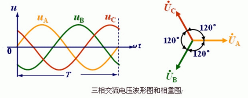
However, the three-phase AC power supply provided by power plants is a sine wave with a difference of 120 ° and a frequency of 50Hz. Before the invention of power electronic devices, it was almost impossible to change the frequency of this power supply. Therefore, the invention of AC motors has been almost 100 years without a good speed control device.
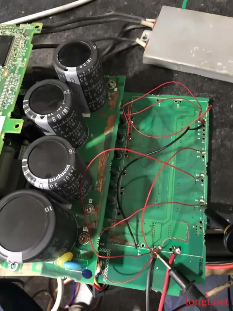
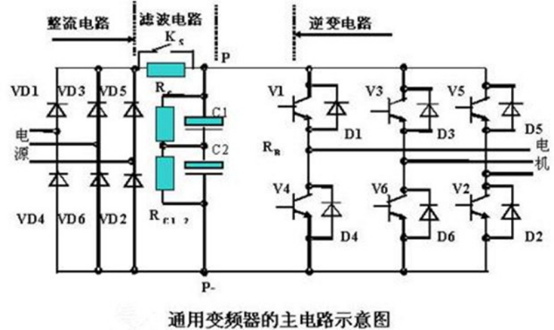
Later, high-power devices such as thyristors, GTR transistors, and IGBT transistors were invented at the end of the last century, and the embedded technology of single-chip microcontrollers became increasingly mature. People found the basic method for asynchronous motor speed regulation. That is to first rectify the three-phase AC voltage into fluctuating DC through diodes or thyristors, and then use capacitors to filter and stabilize it into stable DC. Six IGBT tubes are used to form an inverter circuit. The microcontroller uses PWM chopping to output a series of variable pulse width square waves, which are used to simulate the equivalent effect of variable frequency AC and achieve the goal of controlling motor speed.
It can be imagined that any curve can use many straight line segments to segment and simulate links. The more straight line segments used for simulation, the more accurate the curve can be described. This is actually the concept of calculus in mathematics.
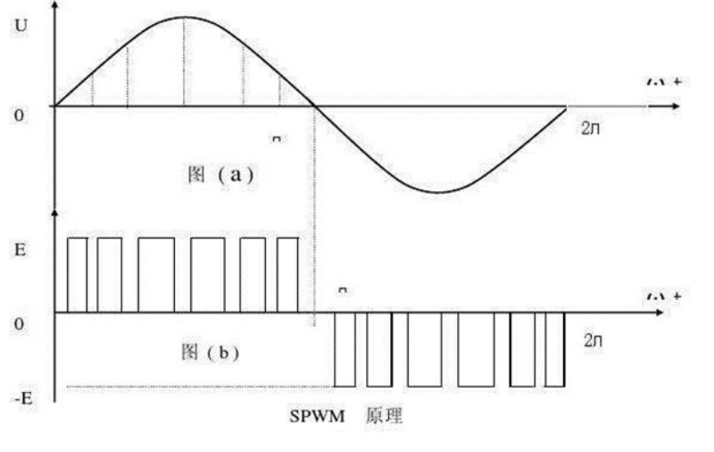
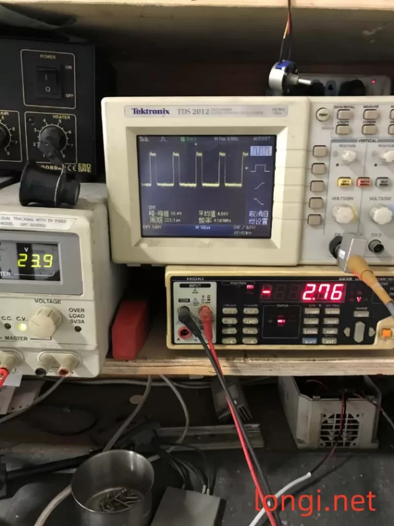
Although a sine wave may seem complex, it can also be simulated and equivalent using many square waves. If a square wave with equal amplitude and variable width is output, and the area of the square wave is equal to the corresponding sine wave area, its effect will be equivalent to the working effect of the sine wave. By controlling the working cycle, the frequency of the output power can be changed, which is called PWM control, Because IGBT switches can achieve very high-speed switching functions, such as having a frequency of tens of K, the output square waves are sufficient, and the simulated sine wave effect is relatively good.
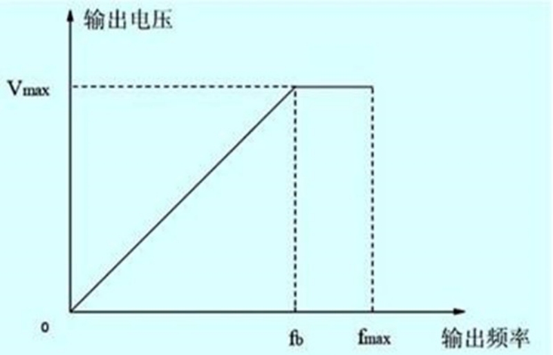
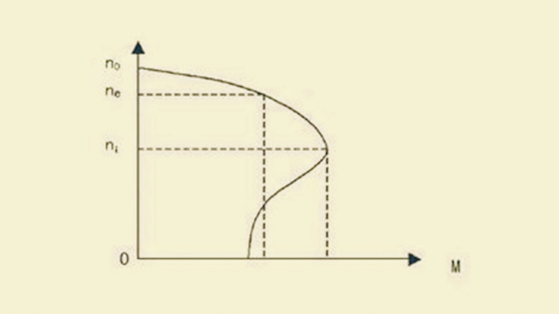
However, changing the frequency of the motor light is not enough, and the voltage should also be adjusted accordingly, otherwise it may cause the motor to work abnormally, such as severe heating and burning. The main reason is that the iron core of the motor is nonlinear, requiring that the voltage also changes when the power frequency changes, in order to control the main magnetic flux to remain constant.
Because: main magnetic flux ≈ motor voltage ÷ (4.44 * frequency * number of electronic winding turns)
Therefore, during frequency modulation, the motor voltage should also change with the frequency, so that the main magnetic flux can remain unchanged and avoid magnetic flux saturation or working in a weak magnetic state.