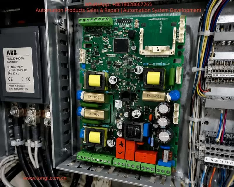
ABB PSTX series soft starters are widely used for starting three-phase asynchronous motors in applications such as pumps, fans, compressors, conveyors, crushers, mixers, cooling towers, and other industrial drive systems. Compared with direct-on-line starting by contactor, a soft starter gradually increases the motor terminal voltage through thyristor phase-angle control. This reduces starting current, limits mechanical shock, minimizes voltage dip on the supply network, and extends the service life of both the motor and the driven mechanical equipment.
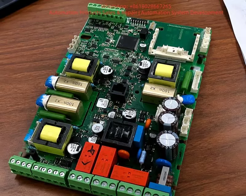
The ABB PSTX series belongs to the more advanced category of soft starters. It integrates the control unit, thyristor power modules, current measurement, voltage measurement, protection logic, and an internal bypass mechanism. Because of this integrated design, the PSTX is able to monitor the main power circuit and detect abnormal operating states more precisely than a simple starter.
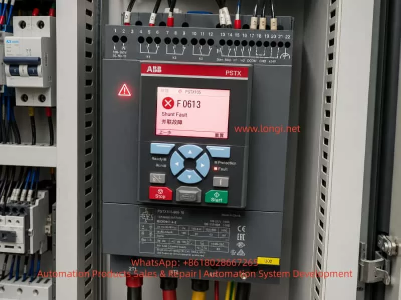
In practical repair work, F0613 Shunt Fault is a relatively common but often misunderstood fault on ABB PSTX soft starters. When the HMI displays “Shunt Fault,” many field technicians may misinterpret it as a problem related to multiple motors connected in parallel, communication parallel operation, or some kind of external parallel control. However, from the perspective of the soft starter main power circuit, this fault usually refers to an abnormal bypass path, an unintended short-circuit path, uncontrolled conduction, or a low-resistance path detected in the main circuit.
Therefore, F0613 should not be treated as a normal parameter alarm or a simple resettable warning. In many cases, it points to a real problem in the main power circuit, internal bypass contactor, thyristor module, external wiring, or load-side circuit. A correct diagnosis must follow the logic of power electronics and three-phase motor control rather than simply clearing the fault code.
1. Basic Working Principle of a PSTX Soft Starter
To understand the F0613 shunt fault, it is necessary to understand the basic structure of a soft starter. In a three-phase soft starter, each phase is controlled by an anti-parallel thyristor pair. During motor starting, the soft starter controls the firing angle of the thyristors and gradually increases the RMS voltage applied to the motor. At the beginning of the start ramp, the motor receives a reduced voltage. As the ramp progresses, the voltage rises until it reaches nearly full line voltage.
This controlled voltage ramp reduces inrush current and avoids the mechanical shock associated with direct-on-line starting. It is especially useful for centrifugal pumps, large fans, belt conveyors, and other loads where sudden torque can damage couplings, belts, bearings, shafts, or hydraulic systems.
However, if the motor current continues to flow through the thyristors during long-term operation, the thyristors generate heat and reduce overall efficiency. For this reason, many medium- and high-end soft starters include a bypass contactor. During the start ramp, the thyristors control the voltage. Once the motor reaches full speed, the bypass contactor closes and carries the main current. The thyristors are then largely removed from the main current path, reducing heat generation and improving efficiency.
The ABB PSTX series has an internal bypass design. This is beneficial for energy efficiency and thermal management, but it also creates an important diagnostic point. If the internal bypass contactor becomes welded, stuck, mechanically jammed, or if a thyristor becomes short-circuited, the soft starter may detect an abnormal shunt path and report a fault such as F0613.
2. Meaning of F0613 Shunt Fault
The essential meaning of F0613 can be understood as follows: the soft starter has detected a main power circuit condition that does not match the expected control state. This may involve an abnormal bypass path, low-resistance path, or uncontrolled conduction between the input and output sides of the soft starter.
In a normal stopped condition, the soft starter should not provide an effective output voltage to the motor. During starting, the thyristors should conduct only according to the firing commands from the control board. During full-speed operation, the bypass contactor may close. During stopping or soft stopping, the bypass contactor and thyristors should return to their proper non-conducting or controlled states.
If the soft starter detects that one or more phases are already conducting when they should not be, or if it detects an abnormal low-resistance path between the input and output terminals, it may interpret this as a shunt fault.
This fault is different from common faults such as phase loss, overcurrent, overload, or overtemperature. A phase loss fault usually indicates missing or unbalanced supply or load phases. An overcurrent fault indicates excessive motor current. An overload fault indicates excessive thermal load. An overtemperature fault indicates insufficient cooling or excessive heat. A shunt fault is more structural in nature. It is usually related to the integrity of the main power circuit and the correct isolation or conduction of the thyristors and bypass path.
3. Common Causes of F0613 Shunt Fault
3.1 Internal Bypass Contactor Contact Welding
One of the most common causes is welded or stuck contacts in the internal bypass contactor. In a PSTX soft starter, the internal bypass contactor closes after the motor has completed its start ramp. Under normal conditions, the bypass contacts carry the motor current during continuous running.
If the motor is started frequently, operates under heavy load, experiences repeated overloads, or suffers from mechanical jamming, the bypass contacts may be exposed to repeated electrical and thermal stress. Over time, the contact surface may become burned, pitted, oxidized, or even welded together.
Once the bypass contactor contacts are welded, they may remain closed even after the control board commands them to open. This creates a direct low-resistance path between the input and output of the soft starter. The control system then detects that the actual main circuit state does not match the expected state and generates a shunt fault.
This condition is potentially dangerous because the soft starter may lose normal control over the motor. In some situations, the motor may remain electrically connected when it should be isolated by the starter. Therefore, repeated reset and restart attempts are not recommended before the main circuit has been checked.
3.2 Short-Circuited SCR Thyristor
Each phase of the soft starter contains an anti-parallel thyristor pair. These thyristors withstand high current, voltage transients, thermal stress, and switching stress during motor starting. If the motor load is too heavy, the start time is too long, the cooling condition is poor, the supply has severe surge voltage, or the output side experiences a short circuit, the thyristors may fail.
A failed thyristor may become short-circuited. Once this happens, the affected phase may show a low-resistance path between the line input terminal and the motor output terminal. A normal thyristor should block voltage when it is not triggered. A shorted thyristor loses this blocking ability and creates an uncontrolled conduction path.
From the soft starter’s monitoring logic, this is similar to an abnormal shunt path. The controller detects that a phase is conducting when it should not be and may report F0613.
A shorted thyristor and a welded bypass contactor can produce similar external measurement results. Both may cause low resistance between L and T terminals. Therefore, further internal inspection is needed to determine whether the fault is in the bypass contactor or in the thyristor power module.
3.3 External Bypass Contactor Wiring Error
Some control panels use an external bypass contactor in addition to or instead of the internal bypass function. In many retrofit projects, old contactors, star-delta starters, or previous bypass circuits may remain inside the cabinet. If the external bypass contactor is wired incorrectly, or if its control logic is wrong, it may connect the input and output sides of the soft starter at the wrong time.
The ABB PSTX already has an internal bypass mechanism. If an external bypass contactor is added, the wiring and control sequence must be carefully designed. The external bypass contactor should not close before the soft starter has completed its starting sequence, and it must open correctly during stop or fault conditions.
If the external bypass contactor closes too early, remains closed after stop, or has welded contacts, the soft starter will detect an unexpected shunt path. This can cause F0613 even if the soft starter itself is not internally damaged.
This type of problem is common in old control cabinets that have been modified. For example, a panel originally designed for direct-on-line starting, star-delta starting, or autotransformer starting may later be converted to soft starter control. If old contactors and wiring are not completely removed or correctly interlocked, an unintended parallel path may remain.
3.4 Mismatch Between Wiring Method and Parameter Setting
Soft starters may support different wiring configurations, such as standard in-line connection and inside-delta connection. These configurations produce different voltage, current, and phase relationships. If the actual main circuit wiring does not match the parameter setting inside the soft starter, the controller may misinterpret the measured signals.
For example, if the unit is physically wired in a standard in-line configuration but the parameter is set for inside-delta operation, the internal measurement logic may not match the actual current path. Conversely, if the motor is wired in inside-delta but the soft starter is configured as in-line, abnormal current and voltage relationships may be detected.
However, a parameter mismatch is usually not the highest-probability cause if the equipment has been operating normally for a long time and suddenly starts reporting F0613. In such cases, hardware faults in the main power circuit should be suspected first. Parameter and wiring mode verification is especially important after new installation, cabinet modification, soft starter replacement, or parameter reset.
3.5 Abnormal Short Path on the Motor or Load Side
The motor, motor cable, terminal box, and downstream contactors may also cause abnormal electrical conditions. Motor winding short circuits, cable insulation breakdown, water ingress in the terminal box, incorrect motor connection, or additional load-side contactors can all create abnormal low-resistance paths.
Although F0613 often points to the soft starter’s internal power circuit or bypass logic, external load-side faults must not be ignored. Industrial sites such as pump rooms, cooling towers, mining plants, chemical plants, and outdoor fan systems often have harsh environments. Moisture, conductive dust, oil mist, vibration, and cable aging can all contribute to insulation failure.
For this reason, the motor output cables should be disconnected during diagnosis to separate the soft starter from the external load. If the fault condition disappears after disconnecting the motor cables, the external circuit must be inspected before condemning the soft starter.
3.6 Current or Voltage Detection Circuit Fault
The PSTX soft starter uses internal current and voltage feedback to determine the operating state of the main circuit. If the current sensor, voltage sampling circuit, connector, ribbon cable, sampling resistor, comparator, or control board input circuit becomes faulty, the control unit may misjudge the actual state of the main circuit.
This cause is less common than a welded bypass contactor or shorted thyristor, but it does occur in real repair work. Surge voltage, poor control power quality, board contamination, moisture, corrosion, or cracked solder joints may affect the measurement circuit.
If the L-to-T resistance measurements are normal, the bypass contactor is not welded, the thyristors are not shorted, and the external wiring is correct, yet F0613 still appears repeatedly, the internal detection circuit or control board should be considered.
4. Initial Field Diagnostic Procedure
4.1 Record the Fault Condition Before Resetting
The first step is not to repeatedly press reset. F0613 is related to the main circuit, so repeated forced resets can expand the damage or create safety risks. The technician should first record when the fault appears:
Does it appear immediately after power-on?
Does it appear only after pressing start?
Does it occur during acceleration?
Does it occur after the motor reaches full speed?
Does it appear during stop or soft stop?
Does it appear intermittently after a period of operation?
The timing of the fault provides important diagnostic information. If the fault appears immediately after power-on before any start command, the most likely causes are a welded bypass contactor, shorted thyristor, or external shunt path. If it appears during acceleration, wiring method, motor load, thyristor firing, and parameter settings should also be checked. If it appears during running, the internal bypass contactor and its feedback logic should be inspected carefully.
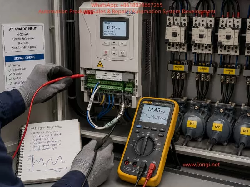
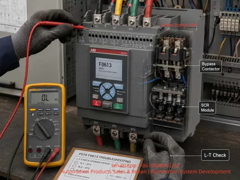
4.2 Measure Resistance Between Input and Output Terminals
After completely isolating the three-phase supply and verifying absence of voltage, measure the resistance between the input and output of each phase:
1L1 to 2T1
3L2 to 4T2
5L3 to 6T3
Use a multimeter in resistance or continuity mode. In a normal stopped and de-energized state, the input and output of each phase should not show a direct low-resistance short.
If one or more phases show nearly 0 ohms or continuity, there is likely an abnormal conduction path. If all three phases are low resistance, the internal bypass contactor may be welded closed or an external bypass path may still be connected. If only one phase is low resistance, a shorted thyristor or one welded bypass contact is more likely.
This measurement is one of the most direct and useful checks for F0613.
4.3 Disconnect the Motor Cables and Measure Again
To determine whether the fault is inside the soft starter or outside in the load circuit, disconnect the motor output cables from the soft starter and repeat the L-to-T resistance measurements.
If the soft starter itself still shows low resistance after the motor cables are removed, the fault is almost certainly inside the soft starter or its connected bypass circuit.
If the low-resistance condition disappears after the motor cables are removed, the motor, cable, terminal box, downstream contactors, or load-side wiring must be checked. In this situation, replacing or repairing the soft starter alone may not solve the problem.
4.4 Inspect for External Bypass or Residual Contactors
In many industrial cabinets, the soft starter is not the original starting device. The cabinet may have been modified from a direct-on-line, star-delta, or autotransformer starter system. Old contactors and wiring may remain inside the panel.
The technician should trace the main power cables and inspect whether any external contactor is connected across the soft starter input and output. Check whether the contactor is mechanically stuck, whether its auxiliary contacts are wired correctly, and whether its control logic is properly interlocked with the soft starter.
A wrongly wired or stuck external bypass contactor can produce the same symptom as an internal soft starter fault.
4.5 Verify Wiring Mode and Parameters
The wiring mode parameter must match the actual main circuit. If the soft starter is installed in the standard in-line configuration, the corresponding parameter must be set accordingly. If inside-delta connection is used, the motor wiring, current setting, and configuration parameters must all match that method.
It is not enough to rely on drawings. The actual cabinet wiring must be inspected, because drawings are often outdated after field modifications.
5. Key Components to Inspect During Repair
5.1 Internal Bypass Contactor
After disassembling the soft starter, the bypass contactor should be inspected first. Look for burned contacts, pitting, melted contact surfaces, mechanical jamming, coil damage, loose connections, and overheated copper bars.
With the contactor in the open state, check whether the main contacts are still conductive. If the contacts remain closed or show very low resistance when they should be open, the contactor is welded or mechanically stuck.
For high-current soft starters, minor contact wear may not immediately cause failure. However, if the contact surface is badly burned or welded, the contactor must be repaired or replaced. Simply polishing the contacts may only provide a temporary solution and is not suitable for reliable long-term operation.
5.2 Thyristor Power Module
The thyristors should be checked with a multimeter and, when necessary, with more advanced test equipment. Compare the forward and reverse resistance of the three phases. If one phase shows a much lower resistance than the others, or if it is nearly shorted in both directions, the thyristor is likely damaged.
However, some thyristor faults are not obvious under cold multimeter testing. A thyristor may have increased leakage current, reduced blocking voltage, or thermal failure that appears only under voltage or load. In such cases, insulation and withstand-voltage testing may be required.
A repair technician should not rely only on a simple continuity test to conclude that all thyristors are good. The measurement results must be compared phase by phase and interpreted with the actual fault behavior.
5.3 Gate Trigger Circuit
If the thyristors are not shorted but the fault occurs during starting, the gate trigger circuit should also be inspected. A missing trigger pulse, incorrect phase synchronization, weak gate drive, or failed isolation component may cause abnormal conduction or serious phase imbalance.
The trigger circuit may include optocouplers, pulse transformers, gate resistors, isolated drive power supplies, and synchronization circuits. Failure in this section may cause the soft starter to start abnormally or report power circuit faults.
Although F0613 is more directly related to shunt or bypass detection, trigger problems can sometimes cause secondary fault symptoms during the start sequence.
5.4 Current Sensors and Sampling Circuit
The current feedback system is essential for the PSTX protection logic. A loose connector, damaged current transformer, cracked solder joint, burned sampling resistor, or failed signal conditioning component can lead to incorrect current feedback.
During repair, inspect current sensor wiring, connectors, ribbon cables, solder joints, and nearby components. Pay special attention to signs of overheating, corrosion, conductive dust, or mechanical stress.
5.5 Control Board and Detection Board
If the power circuit measurements are normal, the bypass contactor is not welded, the thyristors are not shorted, the motor circuit is healthy, and the wiring mode is correct, but the F0613 fault still appears repeatedly, the control board or detection board may be misjudging the main circuit state.
Possible causes include unstable control power, excessive ripple in the internal power supply, drifted reference voltage, failed comparator circuit, damaged input protection components, optocoupler aging, moisture leakage on the PCB, or contamination by conductive dust.
Board-level diagnosis requires careful inspection and signal measurement. In harsh industrial environments, board contamination and moisture-related leakage are common causes of intermittent and misleading faults.
6. Fault Symptom Patterns and Diagnostic Direction
If F0613 appears immediately after power-on before any start command, the most likely causes are internal bypass contact welding, shorted thyristor, or an external bypass path that is already closed.
If the fault appears immediately after pressing start, the technician should check not only the internal power circuit but also wiring mode, motor connection, parameter configuration, and thyristor triggering.
If the fault appears after the motor reaches full speed, the internal bypass contactor should be checked carefully. It may be failing to close correctly, chattering, overheating, or producing abnormal feedback.
If the fault appears during stopping, inspect whether the bypass contactor releases correctly and whether there is any residual external shunt path. Also check whether the load has regenerative or backfeed effects that may interfere with detection.
If the fault is intermittent and can be reset temporarily, suspect unstable mechanical contacts, loose terminals, thermal-related component failure, control board signal drift, or intermittent insulation problems.
7. Safety Precautions During Diagnosis
A soft starter is a high-power three-phase electrical device. Repair work must be performed only after complete isolation, lockout, voltage verification, and appropriate safety procedures.
The input terminals may remain live even when the motor is stopped. Some cabinets may also contain separate control voltage, external bypass supply, capacitor circuits, or backfeed sources. Before measuring resistance, all power sources must be isolated. A multimeter resistance range must never be used on a live circuit.
When removing motor cables, mark the phase sequence clearly to avoid incorrect reconnection. After repair, all main circuit terminals and copper bar connections must be tightened to the proper torque. Loose power terminals can cause overheating, arcing, and repeated failure.
After replacing parts or repairing the main circuit, the soft starter should not be immediately returned to full-load operation. It should first be tested under safe conditions, then with the motor connected, and finally under normal load. During testing, monitor the three-phase current balance, start ramp behavior, bypass contactor action, fault history, and thermal condition.
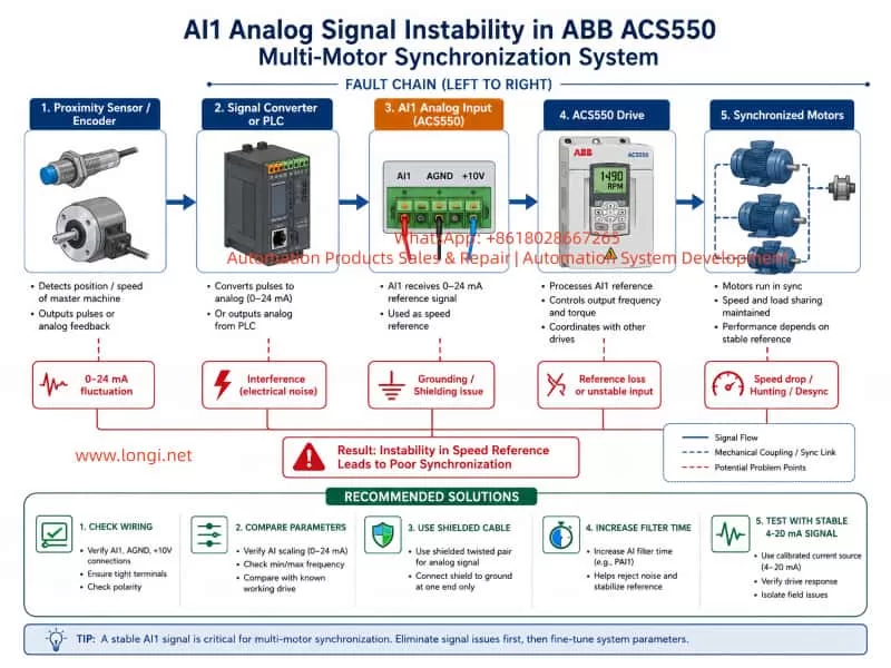
8. Practical Repair Logic for F0613
The key to diagnosing ABB PSTX F0613 is to focus on one question: is there an unintended conduction path in the main power circuit?
If the L-to-T resistance is low when the soft starter is stopped and de-energized, the diagnosis should focus on the bypass contacts, thyristor modules, and external bypass wiring.
If the L-to-T resistance is normal but the fault occurs during starting, check the wiring mode, parameter setting, motor condition, current feedback, voltage feedback, and trigger circuit.
If the main power circuit is normal and the external circuit is confirmed healthy, but the fault still appears, the detection circuit or control board may be causing a false shunt fault.
The diagnosis should proceed in the following order:
First, record the fault timing and operating condition.
Second, isolate power and measure the main circuit resistance.
Third, disconnect the motor cables and repeat the measurement.
Fourth, inspect external bypass contactors and residual old wiring.
Fifth, check the internal bypass contactor and thyristor modules.
Sixth, verify wiring mode and parameter configuration.
Seventh, inspect current and voltage detection circuits.
Finally, evaluate the control board if all power circuit checks are normal.
This sequence prevents unnecessary replacement of expensive components and reduces the risk of misdiagnosis.
9. Conclusion
ABB PSTX F0613 Shunt Fault is a main-circuit-related fault. It usually means that the soft starter has detected an abnormal shunt path, bypass path, or uncontrolled low-resistance conduction state. It should not be treated as a simple parameter warning or a normal resettable alarm.
The most common causes include internal bypass contactor welding, SCR thyristor short circuit, external bypass wiring error, mismatch between wiring method and parameter setting, motor or cable short path, and internal detection circuit malfunction.
In real repair work, the most effective starting point is to isolate power and measure the resistance between the line input and motor output terminals of each phase. If a low-resistance path exists between L and T, the fault direction becomes clear: bypass contactor, thyristor module, or external shunt wiring. If the main circuit resistance is normal, the technician should then investigate wiring configuration, current and voltage feedback, trigger logic, and control board detection.
For long-running equipment used in heavy-load, high-temperature, humid, dusty, or frequently started applications, F0613 has a strong hardware fault implication. A careful step-by-step diagnosis of the main circuit, bypass mechanism, thyristor modules, load circuit, and detection electronics is essential for accurate repair.
The core principle is simple: a soft starter should only conduct when its control logic commands it to conduct. If the unit detects conduction when it should be off, or detects a bypass path that does not match the expected state, it will report a shunt fault. Understanding this principle makes the diagnosis of ABB PSTX F0613 much clearer and prevents unnecessary guesswork during repair.