In hydraulic servo systems used in injection molding machines, hydraulic presses, die-casting machines, rubber machinery, and other industrial equipment, the Inovance IS580 hydraulic servo drive performs several critical functions. These include motor speed control, pressure closed-loop control, flow closed-loop control, temperature protection, and hydraulic response management.
When an IS580 drive reports faults such as Err45 and Err46, the equipment may fail to start, stop immediately after startup, or remain locked in an alarm state. These faults should not be treated simply as “the drive is defective.” It is also not appropriate to immediately replace the IGBT module or power board.
In many cases, Err45 and Err46 are related to the motor temperature feedback circuit, pressure sensor feedback circuit, 24 VDC control supply, analog input wiring, common reference terminals, or the control board signal-conditioning circuit.
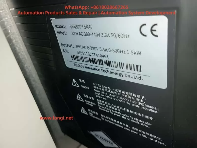
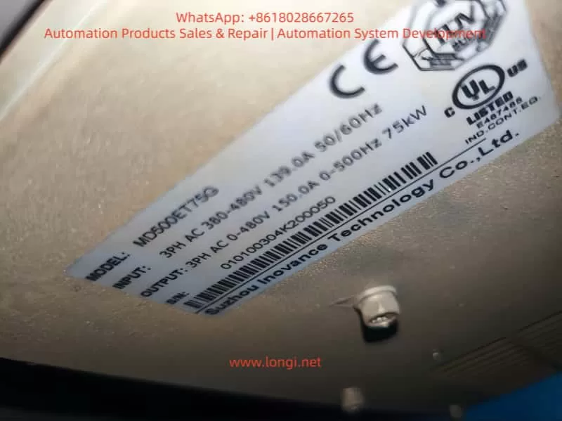
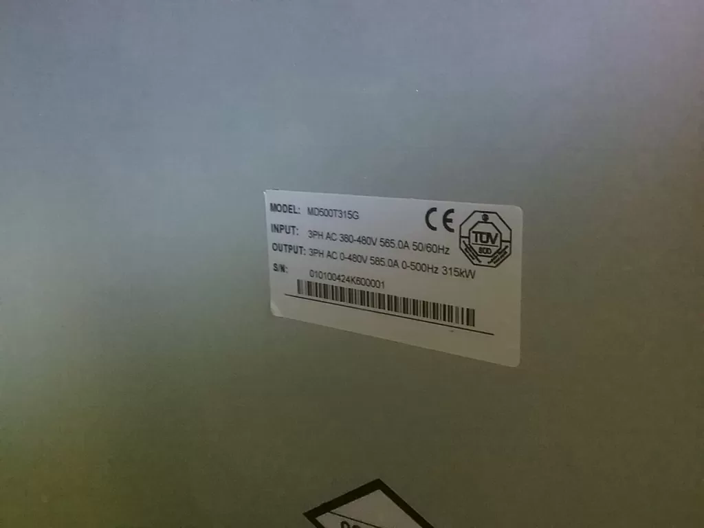
This article uses a typical Inovance hydraulic servo drive, such as the IS580T070-R1-1-EST, 37 kW, 380–480 VAC input model, as an example. It explains how to identify, diagnose, and repair suspected Err45 and Err46 faults in a systematic manner.
1. Confirm the Actual Alarm Code Before Starting Diagnosis
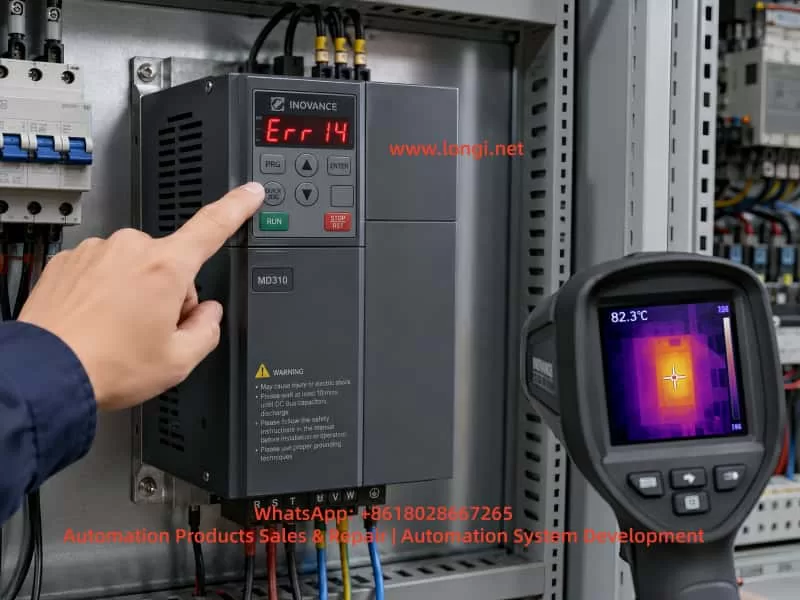
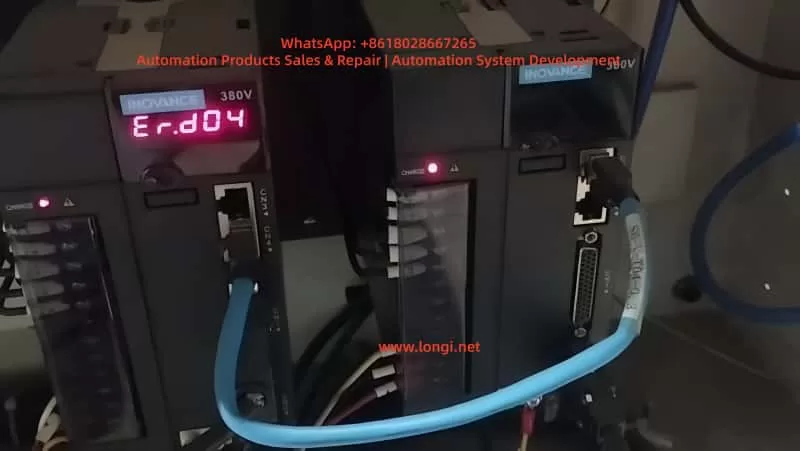
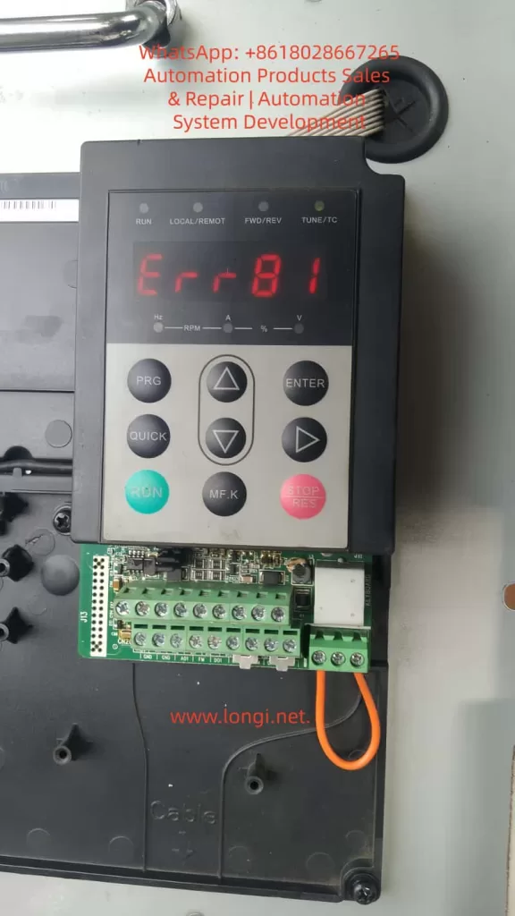
Before troubleshooting, the first step is to confirm the real alarm code.
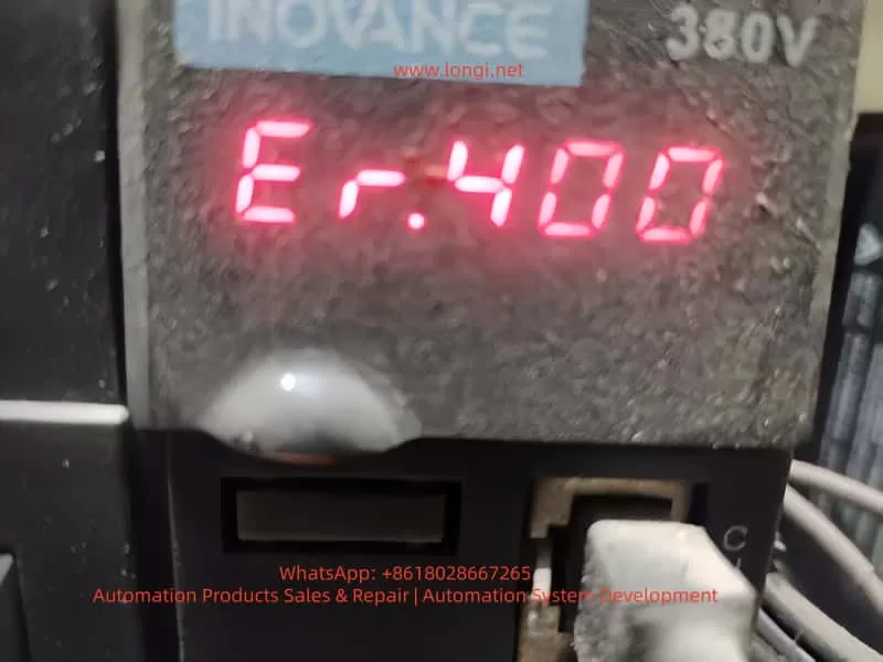
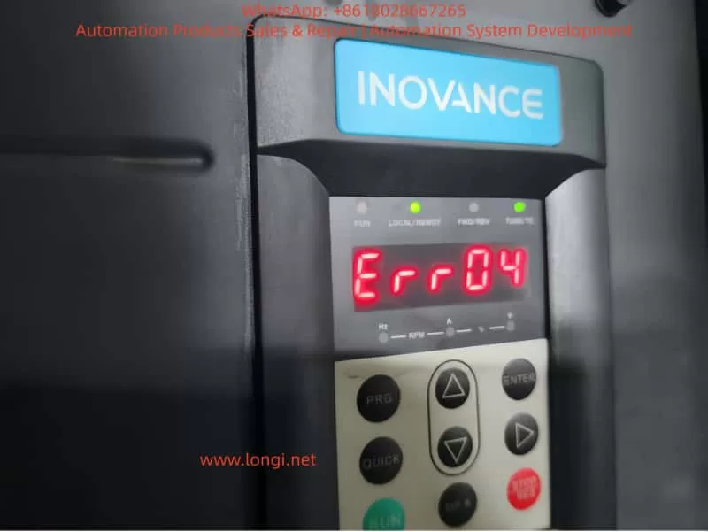
When a mobile phone records a seven-segment LED display, the displayed characters may appear incomplete, distorted, overlapped, or flashing. For example, “Err45” or “Err46” may appear in a video as something similar to “E8.8.85,” “E8.8.86,” or other unclear characters.
This happens because most LED displays use multiplex scanning. The drive scans each digit very quickly. Human eyes see a complete number, but the camera shutter may capture only part of the scan cycle.
Therefore, before diagnosing the drive:
- Record a video instead of taking only a single photo.
- Use slow-motion recording if available.
- Film the display from close range.
- Observe whether the fault code is fixed or alternates between two alarms.
- Record whether the alarm occurs immediately after power-on, when the motor starts, or after running for a period of time.
- Take photos of the drive terminals, motor terminal box, pressure sensor, and external wiring.
If Err45 and Err46 appear alternately, this usually indicates two different feedback-related faults rather than one main power circuit failure.
2. Basic Meaning of Err45 and Err46
For an Inovance IS580 hydraulic servo system, the following diagnostic direction should be considered first:
| Fault Code | Main Diagnostic Direction | Related Components |
|---|---|---|
| Err45 | Motor temperature feedback fault, PTC circuit abnormality, actual motor overheating | Motor temperature cable, PTC sensor, thermal switch, connector, terminal block, control board temperature input |
| Err46 | Pressure sensor feedback fault, pressure analog signal out of range, sensor supply problem | Pressure sensor, 24 VDC supply, analog input, shielded cable, analog common terminal, control board analog input circuit |
Different drive firmware versions, machine builders, and parameter configurations may use slightly different alarm descriptions. Therefore, the final diagnosis should always be confirmed against the correct IS580 manual, the machine electrical drawing, and the original parameter backup.
However, both Err45 and Err46 are generally feedback-detection faults. They are not typical faults such as IGBT short circuit, DC bus undervoltage, output phase loss, or braking unit failure.
For this reason, the correct troubleshooting sequence is:
External wiring → sensor condition → terminal connections → low-voltage supply → control board
Do not begin by replacing the power module.
3. Why Pressure Feedback Is So Important in a Hydraulic Servo System
A standard inverter can run a motor when it receives a run command and frequency reference. A hydraulic servo drive is more complex.
In a hydraulic servo system, the drive adjusts motor speed and torque according to pressure and flow feedback signals. The control logic can be simplified as follows:
Pressure command → Actual pressure feedback → Error calculation → Motor speed adjustment → Hydraulic pump output adjustment → Actual pressure reaches the target value.
If the pressure sensor signal is missing, unstable, out of range, incorrectly configured, or disconnected, the drive cannot accurately determine the actual hydraulic pressure.
To avoid uncontrolled pressure increase, pump overload, low-pressure operation, or dangerous hydraulic movement, the drive may stop and generate a pressure feedback alarm.
Therefore, when Err46 occurs, it does not always mean that the hydraulic pressure itself is abnormal. In many cases, it means that the drive cannot read a valid pressure signal.
Possible causes include:
- No 24 VDC supply to the pressure sensor;
- Loose pressure sensor connector;
- Broken pressure signal wire;
- Open or incorrect analog common terminal;
- Wrong setting between 0–10 V and 4–20 mA;
- Damaged pressure sensor;
- Moisture or oil contamination in the connector;
- Incorrect shielding or severe electrical interference;
- Analog input circuit failure on the drive control board;
- External 24 VDC supply fluctuation.
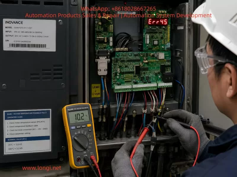
4. Err45: Motor Temperature Protection Circuit
Hydraulic servo motors are commonly equipped with an internal temperature protection element. Typical types include:
- PTC thermistor;
- NTC thermistor;
- Normally closed or normally open thermal switch;
- KTY temperature sensor;
- Motor temperature feedback integrated into the encoder connector.
In industrial servo motors, PTC protection is very common. At normal temperature, the PTC resistance remains low. When the motor reaches the protection temperature, the resistance rises sharply. The drive monitors this circuit to determine whether the motor is overheating.
When Err45 occurs, it does not automatically mean that the motor winding is burnt.
In real maintenance cases, Err45 is often caused by an abnormal temperature feedback circuit rather than true motor overheating.
Common causes include:
- Broken motor temperature cable;
- Loose aviation connector;
- Oxidized connector pins;
- Oil or water inside the motor terminal box;
- Cable insulation damage caused by heat;
- Open-circuit PTC sensor;
- Incorrect wiring after maintenance;
- Loose intermediate terminal block;
- Damaged temperature input circuit on the control board;
- Actual motor overheating caused by overload, poor ventilation, or hydraulic system problems.
Hydraulic servo motors often operate under high load, high oil temperature, and high ambient temperature. If the hydraulic system has continuous overflow, pump seizure, poor cooling, excessive pressure, or heavy mechanical load, the motor may actually overheat.
5. Field Inspection Procedure for Err45
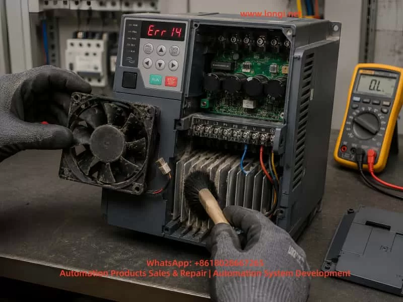
Step 1: Check Whether the Motor Is Actually Overheating
After stopping the equipment, use an infrared thermometer to measure:
- Motor housing temperature;
- Motor terminal box temperature;
- Cooling fan area temperature;
- Hydraulic pump temperature;
- Hydraulic oil temperature;
- Drive heatsink temperature.
If the motor is extremely hot, has a burning smell, or the cooling fan is not operating, mechanical and cooling problems must be resolved first.
Check the following items:
- Is the motor fan running?
- Is the airflow path blocked?
- Is the hydraulic oil temperature too high?
- Is the oil cooler working properly?
- Is the hydraulic pump mechanically overloaded?
- Is the relief valve continuously bypassing oil?
- Is the system pressure higher than the normal setting?
- Are the motor parameters correct?
- Is the motor power rating suitable for the hydraulic pump?
Step 2: Measure the Motor Temperature Circuit
Disconnect the main power supply and wait until the DC bus is fully discharged. A 37 kW drive contains significant stored DC bus energy. Do not touch control terminals or power terminals immediately after power-off.
Locate the motor temperature feedback wires and measure the resistance between the two temperature terminals.
Typical interpretations are:
| Measurement Result | Possible Cause |
|---|---|
| Infinite resistance or open circuit | Broken cable, loose connector, damaged PTC, disconnected terminal |
| Near 0 Ω | Short circuit, damaged component, incorrect wiring |
| Stable resistance within expected range | Temperature circuit is probably normal |
| Resistance changes while moving the cable | Broken conductor, loose plug, poor crimping |
| Resistance increases sharply when motor is hot | Motor may actually be overheating or PTC is operating |
The exact resistance value depends on the motor manufacturer and sensor type. Do not judge the circuit only by a single resistance value. Compare with a known-good motor if possible, or refer to the motor documentation.
Step 3: Inspect Both Motor Side and Drive Side
Many technicians inspect only the drive terminal. However, the motor-side connector is often the real source of the fault.
Pay particular attention to:
- Motor aviation connector pins;
- Encoder connector;
- Terminal box wiring;
- Cable chain bending points;
- Oil contamination;
- Moisture ingress;
- Loose terminal screws;
- Oxidized connectors;
- Improper reconnection after previous maintenance.
The temperature feedback circuit must be checked from the motor all the way to the drive input terminal.
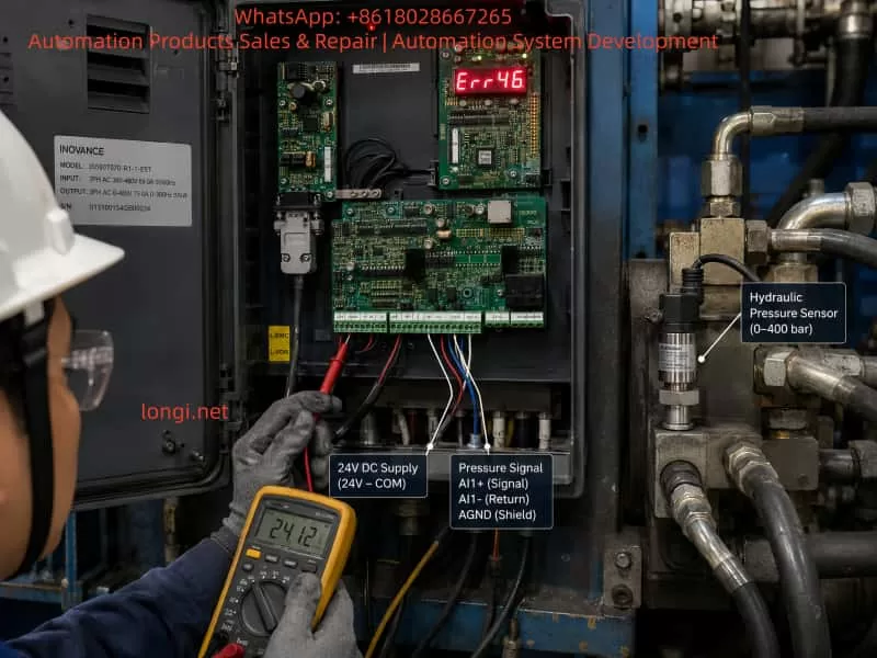
6. Err46: Pressure Sensor Fault Diagnosis
Hydraulic pressure sensors usually use one of the following output formats:
- 0–10 V;
- 0–5 V;
- 4–20 mA.
The most common types are 0–10 V and 4–20 mA.
A typical pressure sensor may have three or four wires:
- Positive supply, usually +24 VDC;
- Negative supply, 0 VDC;
- Signal output, 0–10 V or 4–20 mA;
- Shield wire, depending on the sensor type.
Before checking the wiring, confirm the actual sensor type and make sure the drive parameters match it.
For example, if the sensor is 4–20 mA but the drive is configured for 0–10 V, the drive may report Err46 even though the sensor itself is healthy.
7. Three-Step Pressure Sensor Test Method
Step 1: Check the Sensor Supply Voltage
Use a multimeter in DC voltage mode and measure the sensor power supply terminals.
Typical expected values include:
- Approximately 24 VDC;
- In some systems, 10 VDC or 12 VDC;
- The voltage should remain stable and should not collapse during alarm conditions.
If the pressure sensor has no supply voltage, inspect:
- Drive 24 VDC output;
- External switching power supply;
- Fuse;
- Terminal block;
- Intermediate relay;
- Common 0 VDC wiring;
- Broken cable;
- Control board 24 VDC output circuit.
If multiple sensors lose power at the same time, the problem is more likely related to the common power supply or common wiring than to a single sensor.
Step 2: Check the Pressure Signal Output
For a 0–10 V pressure sensor, measure the signal wire relative to the analog common terminal.
Normally, the output voltage should change smoothly with hydraulic pressure. For example:
- Near 0 V when pressure is low;
- Approximately 4–6 V at medium pressure;
- Close to 10 V at full-scale pressure.
For a 4–20 mA sensor, measure the current in series or measure the voltage across a known sampling resistor.
Typical diagnostic conclusions are:
| Signal Condition | Possible Cause |
|---|---|
| Signal always 0 V | No sensor supply, broken signal wire, failed sensor |
| Signal always at maximum value | Signal shorted to 24 V, failed sensor, actual pressure overload |
| Signal unstable or jumping | Loose connection, poor shielding, interference, unstable supply |
| Signal normal but drive still alarms | Incorrect parameter settings, analog common problem, control board input failure |
| Alarm changes when cable is moved | Broken cable conductor, loose connector, poor crimping |
Step 3: Check the Drive Analog Input Terminal
Even if the sensor output is normal, verify that the signal actually reaches the drive.
Measure the signal at several locations:
- At the pressure sensor output;
- At the intermediate terminal block;
- At the drive analog input terminal;
- At the analog common terminal;
- At the control board connector.
If the signal is correct at the sensor but missing at the drive, the fault is in the cable, terminal block, connector, or wiring arrangement.
If the signal is correct at the drive terminal but Err46 remains active, the control board analog input circuit becomes a strong suspect.
8. Why Err45 and Err46 Can Occur Together
Err45 and Err46 relate to different feedback signals, but they may appear together because of a shared fault source.
Common shared causes include the following.
1. Abnormal 24 VDC Control Supply
Pressure sensors usually depend on 24 VDC. Some encoder interfaces, external temperature modules, and control circuits may also depend on the same low-voltage supply.
If the 24 VDC power supply is unstable, overloaded, shorted, or heavily fluctuating, multiple feedback signals may become abnormal.
2. Loose or Open Common 0 VDC
In analog control systems, 0 VDC is not only the negative supply wire. It is also the signal reference point.
If the pressure sensor signal wire remains connected but the analog common terminal is open, the drive may read unstable, floating, saturated, or incorrect voltage values.
A common-terminal problem may also affect other low-voltage detection circuits.
3. Oil, Water, or Corrosion at the Terminal Block
Hydraulic equipment often operates in oily environments. If the electrical cabinet sealing is poor, oil mist, moisture, dust, and corrosion may enter the terminal area.
This can cause:
- High-resistance leakage;
- Analog signal drift;
- Oxidized terminals;
- Short circuits;
- 24 VDC leakage to ground;
- Increased contact resistance;
- Unstable feedback signals.
4. Signal Cables Installed Together With Motor Cables
If pressure sensor cables, temperature feedback wires, and encoder cables are routed together with U/V/W motor output cables for a long distance, they may be affected by PWM switching interference.
This can cause:
- Unstable pressure feedback;
- Analog input over-range alarms;
- Encoder communication errors;
- Temperature input misjudgment;
- Unstable motor operation.
Analog signal cables should use shielded twisted-pair cable and should be routed separately from power cables. Shield grounding should follow the original machine design and the drive manufacturer’s requirements.
5. Control Board Analog Input Circuit Failure
If the pressure sensor, external wiring, 24 VDC supply, and terminal block all test normally, the control board becomes a likely fault source.
Common damaged parts on the control board include:
- Analog input operational amplifiers;
- TVS surge protection devices;
- Current-limiting resistors;
- Optocouplers;
- 24 VDC to 5 VDC or 3.3 VDC regulators;
- ADC input circuits;
- Connector pins;
- Temperature detection comparators;
- MCU peripheral sampling circuits.
Such faults usually require board-level inspection, component-level measurement, and analog signal simulation.
9. Do Not Directly Short the Motor Temperature Protection Input
Some technicians may short the motor temperature protection input temporarily in order to make the machine run.
This is risky.
Shorting the temperature input may temporarily remove Err45, but it also disables motor thermal protection. If the motor is actually overheating because of poor cooling, pump overload, blocked oil flow, high hydraulic pressure, or fan failure, continued operation may cause:
- Motor winding burnout;
- Encoder damage;
- Bearing failure;
- Hydraulic pump seizure;
- Drive overcurrent;
- IGBT module damage;
- Mechanical equipment failure.
A temporary simulation may be used only by experienced personnel for diagnostic purposes and only after confirming that the motor temperature is safe. The original thermal protection must be restored after diagnosis.
Similarly, do not blindly inject a voltage or connect a resistor to simulate the pressure sensor signal. Incorrect pressure simulation can cause dangerous hydraulic movement or incorrect pressure control.
10. Recommended Complete Troubleshooting Sequence
For an Inovance IS580 hydraulic servo drive showing Err45 and Err46, use the following sequence.
Step 1: Record the Current Condition and Save Parameters
Before resetting the drive or disconnecting power, record:
- Drive model;
- Alarm code;
- Parameter group settings;
- Motor nameplate;
- Pressure sensor nameplate;
- Control terminal wiring;
- Machine electrical drawings;
- Machine condition when the alarm occurs;
- Whether the motor, sensor, pump, or control board was recently replaced.
If the drive can still access the parameter menu, save the parameters before making changes. Pressure signal type, scaling, zero-point adjustment, maximum pressure setting, and control mode can all affect fault diagnosis.
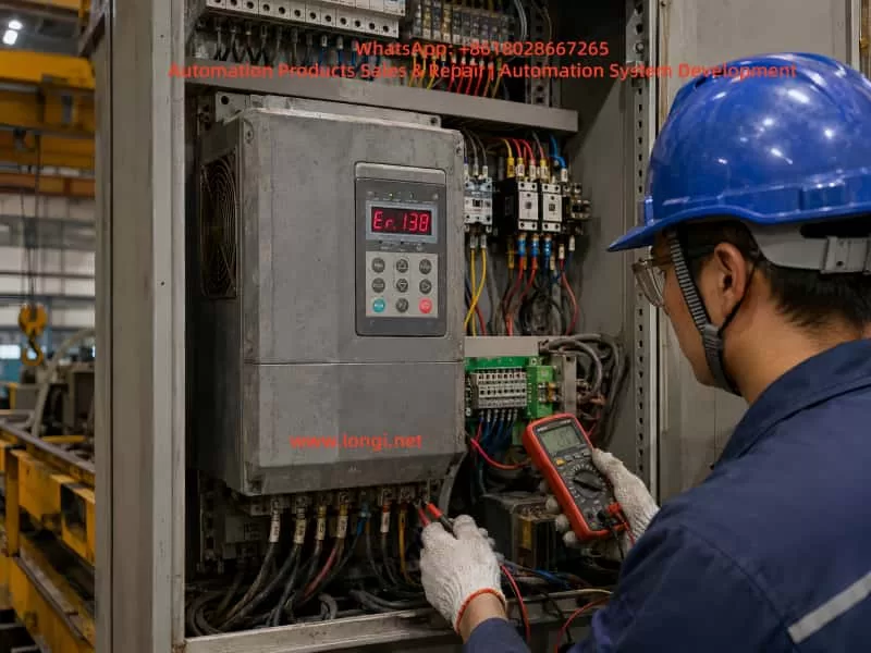
Step 2: Check the Control Power Supply
Measure:
- Drive 24 VDC control output;
- External 24 VDC power supply;
- Pressure sensor supply voltage;
- Stability between 24 VDC and 0 VDC;
- Insulation between 24 VDC and ground;
- Whether the control voltage drops when the alarm occurs.
Step 3: Check the Motor Temperature Circuit
Measure:
- Temperature feedback resistance;
- Motor-side connector;
- Drive-side terminal;
- Intermediate terminal block;
- Cable bending points;
- Resistance variation while moving the cable.
Step 4: Check the Pressure Sensor Circuit
Measure:
- Sensor supply voltage;
- Sensor output signal;
- Sensor signal type;
- Drive parameter settings;
- Whether the signal changes with pressure;
- Connector contamination, looseness, or corrosion.
Step 5: Check Analog Common and Shielding
Confirm:
- Analog common terminal connection;
- Relationship between sensor 0 VDC and drive analog common;
- Shield wire grounding method;
- Separation between analog signal cables and motor power cables;
- Absence of incorrect grounding or multiple grounding points.
Step 6: Inspect the Control Board Only After External Circuits Are Confirmed Normal
If all external checks are normal, proceed to control board inspection.
Check whether:
- The analog input can receive a standard test voltage;
- The temperature input can recognize a correct resistance value;
- 24 VDC, 5 VDC, and 3.3 VDC supplies are stable;
- The analog channel is damaged;
- The board connector solder joints are loose;
- There is corrosion, oil contamination, or moisture damage on the board.
11. Practical Advice for Machine Operators
For non-professional users, the following basic checks can be completed before sending the drive for repair:
- Check whether the servo motor is excessively hot.
- Check whether the motor cooling fan operates normally.
- Check whether the motor temperature connector is loose.
- Check whether the pressure sensor connector is loose, oily, damaged, or corroded.
- Measure whether the pressure sensor has a stable 24 VDC supply.
- Measure whether the pressure signal changes with hydraulic pressure.
- Check whether sensor cables are routed together with motor power cables.
- Check whether drive control terminals show signs of moisture, corrosion, overheating, or loose wiring.
- Do not short the motor temperature protection terminal permanently.
- Do not replace the IGBT module before checking the feedback circuits.
12. Conclusion
When an Inovance IS580 hydraulic servo drive reports suspected Err45 and Err46 faults, the first diagnostic focus should be the motor temperature feedback circuit and pressure sensor feedback circuit, not the IGBT module or main power board.
Err45 requires inspection of the motor PTC circuit, temperature cable, aviation connector, terminal block, motor cooling condition, and hydraulic load.
Err46 requires inspection of the pressure sensor supply voltage, output signal, analog input type, analog common terminal, shielding, and control board analog input circuit.
If both faults occur together, special attention should be given to the 24 VDC control supply, analog common wiring, control cable harness, terminal contamination, and control board connector condition.
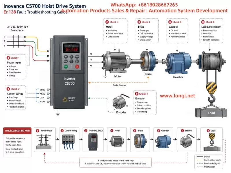
The most effective diagnostic method is to follow the signal path step by step:
Sensor output → terminal block → drive input terminal → control board sampling circuit
This process allows technicians to quickly distinguish between an external wiring or sensor problem and an internal drive control board fault.
For high-power hydraulic servo drives such as 37 kW units, blindly bypassing protection circuits, forcing the machine to run, or replacing the power module without testing the feedback system can significantly increase repair cost and equipment risk. The correct approach is to first verify whether the feedback signals are real, stable, correctly wired, and correctly matched to the drive parameters.