1. Introduction
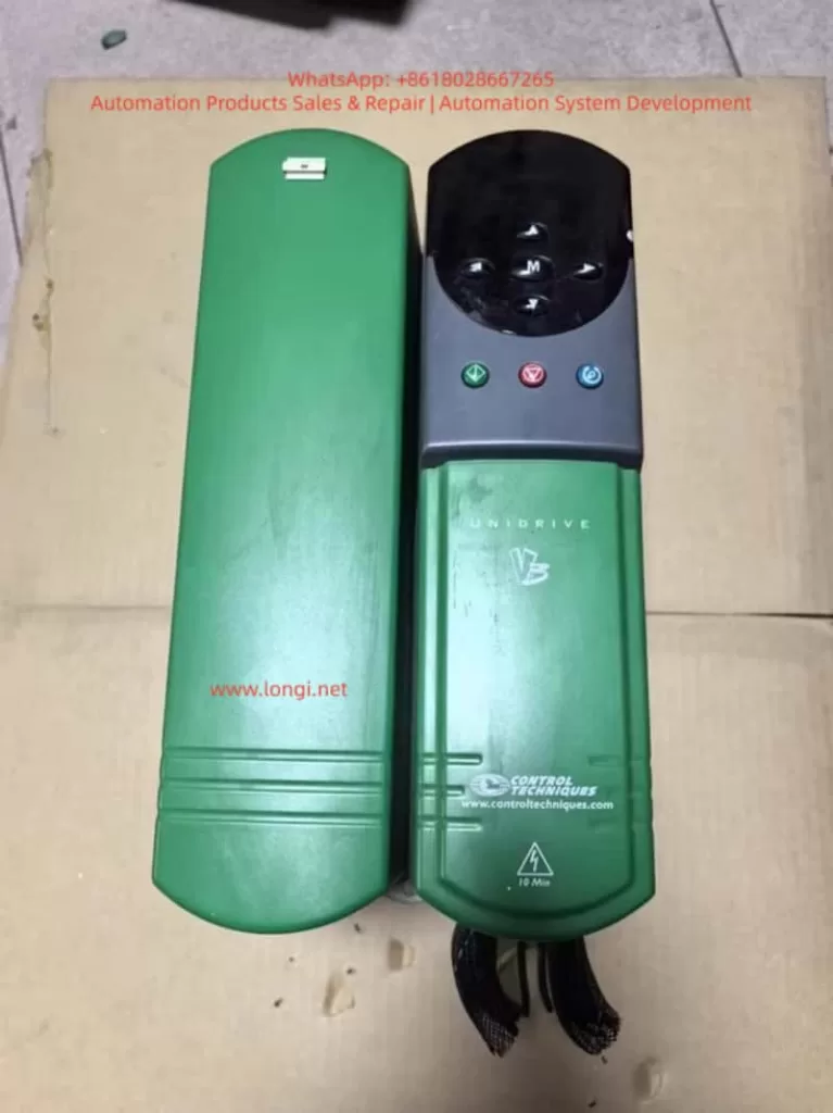
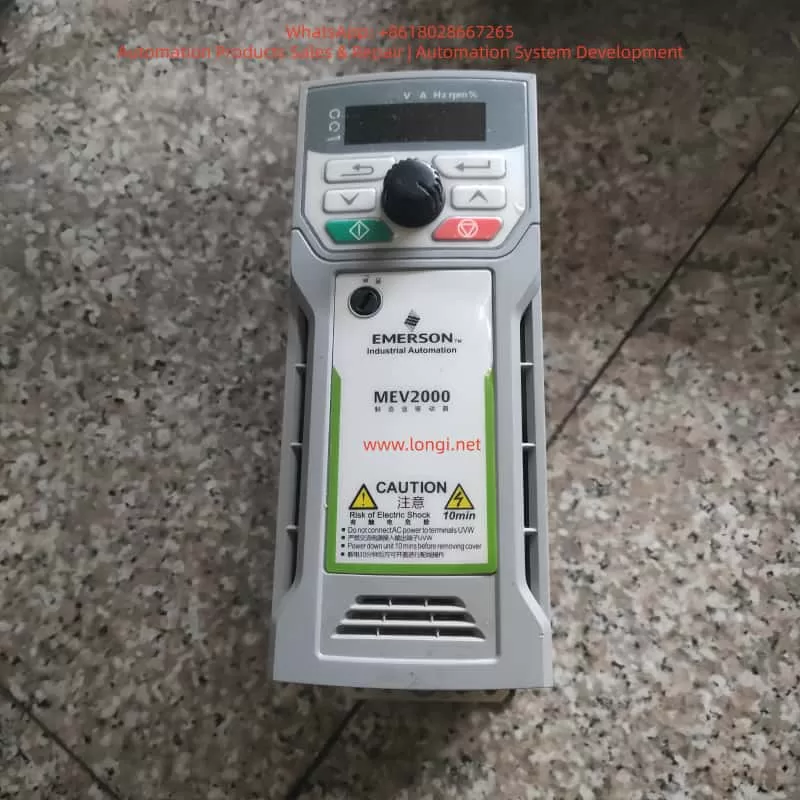
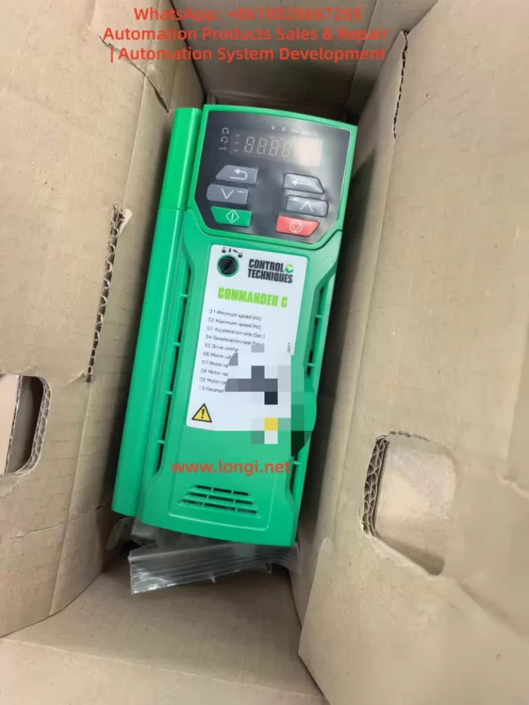
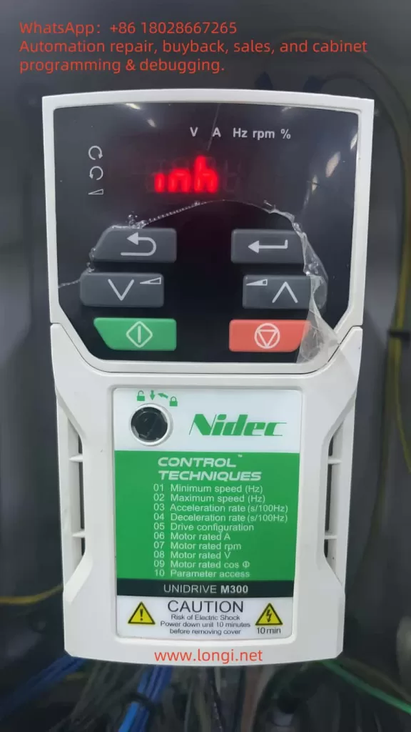
The Nidec Control Techniques Unidrive M300 is widely used in industrial applications such as pumps, fans, conveyors, mixers, packaging machines, textile machinery, woodworking equipment, and general-purpose motor control systems. Its compact design, simple commissioning structure, and reliable motor-control capability make it suitable for a large number of standard automation applications.
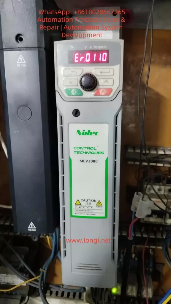
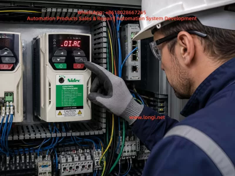
During operation, the drive may display a fault such as:
OI.AC
Er.OI.AC
This fault indicates an instantaneous AC output over-current condition. It is not simply a normal motor overload alarm. Instead, the drive has detected that the output current has risen above the internal protection threshold within a very short period of time. To protect the IGBT power module, motor cable, and motor winding, the drive immediately blocks its output.
An OI.AC trip should therefore be treated as a protection event requiring systematic troubleshooting. Repeatedly resetting the drive and restarting the machine without identifying the root cause may lead to IGBT damage, motor winding failure, cable burning, or more serious control cabinet faults.
The correct diagnostic approach is to determine when the fault occurs, inspect the mechanical load, test the motor and cable insulation, verify motor parameters, examine output switching devices, and finally determine whether the fault is external or internal to the drive.
2. What Does OI.AC Mean?
The Unidrive M300 converts the fixed AC input supply into a variable-frequency, variable-voltage three-phase output for the motor.
Its energy path is generally:
AC Input Supply
      ↓
Rectifier Bridge
      ↓
DC Bus
      ↓
DC Bus Capacitors
      ↓
IGBT Inverter Stage
      ↓
U / V / W Output
      ↓
Motor and Mechanical Load
The drive continuously monitors its output current through internal current sensing circuits. If the current rises sharply above the allowed limit, the drive immediately disables the IGBT output stage.
This high-speed protection is different from a normal thermal overload trip.
A thermal overload condition occurs when the motor draws excessive current over a relatively long period and heats up gradually. By contrast, an OI.AC fault usually means that a very high current appeared suddenly.
Typical causes include:
- Phase-to-phase short circuit in the motor cable
- Motor winding short circuit
- Motor insulation breakdown to earth
- Mechanical jam or locked rotor
- Excessively short acceleration time
- Incorrect output contactor switching
- Incorrect motor parameter settings
- Improper motor connection
- IGBT module damage
- Current detection circuit failure
For this reason, OI.AC should not be treated as a minor parameter issue. It is a fast protection response against an abnormal output current condition.
3. Diagnose According to the Moment the Fault Occurs
The timing of the fault is one of the most important diagnostic clues.
| When OI.AC Occurs | Likely Cause |
|---|---|
| Immediately after power-up | Internal drive fault, IGBT failure, current sensing fault, drive power circuit issue |
| Immediately after start command | Motor cable short circuit, motor winding problem, jammed load, brake not released |
| During acceleration | Acceleration time too short, excessive load inertia, heavy load, incorrect motor parameters |
| At low speed | High torque demand, motor stall, vector control setting issue, mechanical resistance |
| At high speed | Cable insulation problem, loose terminal, vibration-related intermittent fault, load fluctuation |
| During deceleration | Output contactor switching, mechanical back-driving, braking-related issue |
| With motor cables removed | Internal drive hardware fault is highly likely |
| Only with one particular motor | Motor, cable, mechanical load, or connection issue |
Before making parameter changes, the maintenance technician should record the actual operating conditions:
- At what frequency did the trip occur?
- Was the motor starting, accelerating, decelerating, or running steadily?
- What was the displayed current before the trip?
- Was the machine loaded or unloaded?
- Was an output contactor operating?
- Had the motor, cable, or drive recently been replaced?
- Did the fault begin after moisture, overload, mechanical damage, or electrical maintenance?
These details often reduce troubleshooting time significantly.
4. Motor Cable Short Circuit and Ground Leakage
4.1 Phase-to-Phase Short Circuit
A short circuit between U, V, and W motor phases can cause an immediate OI.AC trip.
Common causes include:
- Damaged motor cable insulation
- Cable crushed by machinery
- Loose copper strands touching adjacent terminals
- Water inside the motor terminal box
- Motor winding short circuit
- Incorrect wiring after motor repair
- Conductive dust inside the terminal box
- Oil, coolant, or moisture contamination
- Cable damage caused by vibration
The first inspection should be visual and mechanical. Check the motor terminals, cable glands, cable tray, junction boxes, and drive output terminals carefully.
A standard multimeter can help identify an obvious short circuit, but it cannot reliably assess insulation quality. A motor may appear normal under the low voltage of a multimeter but fail under the high dv/dt PWM output of a variable frequency drive.
Therefore, insulation testing is necessary.
4.2 Motor-to-Earth Insulation Failure
Motor insulation deterioration is one of the most common reasons for intermittent over-current or output-related faults.
Typical warning signs include:
- The fault occurs more frequently in humid weather.
- The motor runs normally when cold but trips after warming up.
- The fault started after the machine was washed or exposed to water.
- The cable is old, oily, or exposed to high temperature.
- The motor has been unused for a long time.
- The fault appears randomly rather than continuously.
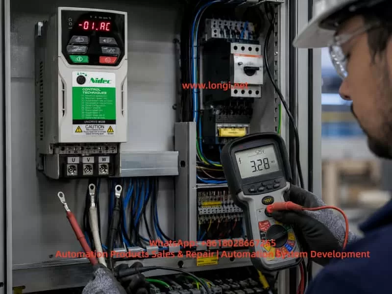
Before insulation testing, disconnect the motor cable completely from the drive output terminals. Never apply a megger directly to a connected VFD output.
The following measurements should be performed:
U-V
V-W
U-W
U-Earth
V-Earth
W-Earth
For many low-voltage motors, a 500 V insulation resistance tester is commonly used. However, the test method and acceptance value should always follow the motor manufacturer’s requirements and local electrical standards.
If insulation resistance is low, the problem may be caused by moisture, cable damage, contaminated terminal boxes, winding degradation, or insulation breakdown inside the motor.
4.3 Long Motor Cables and PWM Reflection
The output of a VFD is not a pure sine wave. It consists of high-frequency PWM pulses. When the motor cable is long, cable capacitance, inductance, and reflected voltage waves can create additional electrical stress.
Possible consequences include:
- Higher motor terminal voltage spikes
- Increased leakage current
- Motor insulation aging
- Bearing current and bearing damage
- Nuisance over-current trips
- EMC interference
- Encoder signal instability
- Sensor communication problems
For long cable installations, an output reactor, dv/dt filter, or sine wave filter may be required depending on drive size, cable length, motor type, and application duty.
A motor that appears to run normally may still suffer accelerated insulation damage if the cable arrangement is not suitable for VFD operation.
5. Mechanical Jamming and Excessive Load
5.1 Mechanical Locking or High Resistance
When the drive receives a start command, the motor must develop torque to overcome the mechanical load. If the mechanical system is jammed, the motor cannot accelerate normally and the current rises quickly.
Common mechanical causes include:
- Failed gearbox
- Seized bearing
- Blocked pump impeller
- Fan blade rubbing against casing
- Conveyor belt jam
- Frozen or hardened material inside a mixer
- Excessive belt tension
- Lack of lubrication
- Misaligned coupling
- Closed mechanical brake
- Foreign object interference
Mechanical faults often produce the following symptoms:
- OI.AC immediately after start
- Motor humming without accelerating
- Current rising sharply
- Motor shaft difficult to turn manually
- Normal operation when the load is disconnected
- Abnormal mechanical noise or vibration
For motors with holding brakes, always verify that the brake coil is energized correctly and that the brake is actually released before the motor starts.
5.2 Acceleration Time Too Short
A large-inertia load needs sufficient acceleration time.
Typical high-inertia applications include:
- Large fans
- Centrifuges
- Heavy conveyors
- Mixers
- Winding machines
- Crushers
- Extruders
- Pumps with high starting torque
- Machines with gear reducers
If the acceleration time is set too short, the drive demands excessive torque from the motor. High torque demand means high current demand. If the current rises above the protection threshold, the drive trips on OI.AC.
A practical correction method is to increase the acceleration time gradually.
For example:
Original acceleration time: 3 seconds
First test value: 10 seconds
Second test value: 15 seconds
Further adjustment: 20–30 seconds if necessary
The correct value depends on the machine inertia, process requirements, motor size, and drive capacity.
The goal is not simply to make acceleration extremely slow. The objective is to reduce the current peak to a safe and stable value while maintaining acceptable production performance.
6. Incorrect Motor Parameters and Wiring Configuration
The motor parameters entered into the Unidrive M300 directly affect magnetic flux, torque production, current control, and protection behavior.
Important parameters include:
- Motor rated voltage
- Motor rated current
- Motor rated frequency
- Motor rated speed
- Motor rated power
- Motor power factor
- Motor connection method
- Control mode
- Acceleration and deceleration time
- Current limit setting
If these parameters do not match the motor nameplate, the drive may produce unstable torque, high current, poor low-speed performance, motor overheating, or over-current trips.
6.1 Incorrect Star/Delta Connection
A common issue involves dual-voltage motors.
For example, a motor nameplate may state:
220 V Delta / 380 V Star
If a 380 V output drive is connected to this motor in Delta configuration, each winding may receive excessive voltage. The motor can become over-fluxed, current can rise sharply, and the motor may overheat or trip on over-current.
Conversely, if a 220 V drive is connected to the motor while the motor is wired in Star configuration, the motor may produce insufficient torque. Under load, it may stall or draw excessive current.
Always verify both the drive output voltage class and the motor terminal connection.
6.2 Incorrect Rated Current Setting
If the motor rated current is set too low, the drive may limit current too early or generate protection trips during normal operation.
If the value is set too high, the motor thermal protection becomes ineffective and the motor may be exposed to excessive current for too long.
Increasing the current limit is not a proper solution for OI.AC unless the entire system has been carefully evaluated.
If the true cause is a cable short circuit, mechanical jam, motor insulation fault, or damaged IGBT, increasing the current limit can make the failure much more destructive.
6.3 Unsuitable Control Mode
Standard V/F control may be sufficient for simple fan and pump applications.
However, applications requiring high starting torque, low-speed torque, rapid response, or stable speed control may require correct vector control settings and proper motor tuning.
Examples include:
- Extruders
- Mixers
- Crushers
- Hoists
- Heavy conveyors
- Winding machines
- Printing machines
- Woodworking machines
- Low-speed constant torque systems
Incorrect control settings may result in current oscillation, unstable torque, low-speed vibration, inability to accelerate, or OI.AC trips.
When appropriate, static or rotating motor autotuning should be performed after confirming that the motor data is correct and that the machine is safe for possible motor movement.
7. Output Contactor Switching and Its Risks
Some installations include an output contactor, isolation switch, bypass arrangement, or multi-motor switching circuit between the drive and the motor.
If these devices switch while the VFD is still producing output, OI.AC can occur.
The reason is that disconnecting or reconnecting the motor while the IGBT stage is actively switching creates a sudden voltage and current disturbance.
Risks include:
- OI.AC trips
- IGBT stress
- Contactor contact damage
- Electrical arcing
- Severe electromagnetic interference
- Motor torque shock
- Premature drive failure
The proper switching sequence should be:
Stop the drive output
      ↓
Disable the drive
      ↓
Confirm motor current has reached zero
      ↓
Switch output contactor
      ↓
Confirm contactor position
      ↓
Enable the drive
      ↓
Restart the motor
Never switch U, V, and W directly while the drive is actively running.
In systems with bypass circuits, multiple motors, reversing circuits, star-delta circuits, or automatic transfer arrangements, PLC timing and electrical interlocking should be inspected carefully.
8. Identifying Internal Drive Faults
When the motor, cable, load, and wiring have been verified, the next step is to determine whether the drive itself has failed.
8.1 Test the Drive with Motor Cables Disconnected
A key diagnostic method is to disconnect the motor output cables completely.
Basic procedure:
Disconnect incoming power
      ↓
Wait for DC bus discharge
      ↓
Remove U, V, W motor cables
      ↓
Confirm no external load is connected
      ↓
Restore power
      ↓
Issue a start command
      ↓
Observe whether OI.AC still occurs
If OI.AC still occurs with U, V, and W disconnected, the fault is likely inside the drive.
Possible internal fault locations include:
- IGBT power module
- IGBT gate driver circuit
- Gate driver optocoupler
- Current sensor
- Current feedback amplifier
- Current sampling resistor
- Drive power supply circuit
- Control board
- DC bus circuit
- Internal wiring or connector issue
8.2 IGBT Failure
The IGBT module is the core power switching component inside the drive.
If an IGBT fails short circuit or develops leakage, the drive may show:
- Immediate OI.AC after start command
- Input fuse failure
- Abnormal output waveform
- Motor vibration or no rotation
- One output phase abnormal
- DC bus fault
- Visible burn damage
- Abnormal resistance readings between output terminals and DC bus
However, replacing only the IGBT module may not solve the problem permanently.
The following should also be inspected:
- Gate driver circuitry
- Gate resistors
- Driver power supply
- Snubber circuit
- DC bus capacitors
- Cooling fan operation
- Heatsink condition
- Current feedback circuit
- External motor cable condition
- Motor insulation condition
If an external short circuit caused the IGBT failure, installing a repaired drive without fixing the motor or cable may result in immediate repeat damage.
8.3 False Over-Current Caused by Current Detection Failure
In some cases, the actual motor current may not be excessive. The drive may trip because the current sensing circuit is faulty.
Potential causes include:
- Hall current sensor failure
- Faulty current feedback power supply
- Drifted sampling resistor
- Failed operational amplifier
- Control board fault
- Loose connector
- Corrosion or moisture damage
- Cracked solder joint
- Excessive power supply ripple
Typical symptoms include:
- OI.AC with no motor connected
- Fault occurs randomly under normal load
- Displayed current is clearly unreasonable
- One phase current reading differs greatly from the others
- Fault remains after mechanical and cable checks
- Drive works temporarily after repair but fails again later
These faults usually require professional repair equipment such as an oscilloscope, isolated power supply, power module tester, and current waveform measurement tools.
9. Standard Troubleshooting Procedure
The following procedure is suitable for most Unidrive M300 and similar VFD over-current faults.
Step 1: Record the Fault Condition
Record:
- When the fault occurs
- Motor frequency at the time of trip
- Displayed current before trip
- Whether the motor is loaded
- Whether the fault occurs during start, acceleration, steady running, or deceleration
- Whether output contactors are used
- Whether the machine has recently been repaired or modified
- Whether water, dust, overload, vibration, or cable damage may be involved
Step 2: Stop Repeated Restart Attempts
Do not continue pressing reset and restarting the drive.
Disconnect the run command, switch off the incoming power, and allow sufficient time for the DC bus capacitors to discharge.
Step 3: Inspect the Mechanical Load
Check:
- Can the motor shaft rotate manually?
- Is the gearbox damaged?
- Is the pump impeller blocked?
- Is the fan rubbing?
- Is the conveyor jammed?
- Is the brake released?
- Is the coupling aligned?
- Are bearings seized?
- Is the belt tension excessive?
- Is there foreign material in the machine?
Step 4: Inspect the Motor and Cable
Disconnect the motor from the drive and check:
U-V
V-W
U-W
U-Earth
V-Earth
W-Earth
Also inspect:
- Cable damage
- Water ingress
- Loose terminals
- Exposed copper strands
- Damaged cable gland
- Terminal box contamination
- Cable crushed by machinery
- Cable routing near high-temperature areas
- Grounding condition
Step 5: Verify Motor Nameplate Data and Drive Parameters
Check:
Motor rated power
Motor rated voltage
Motor rated current
Motor rated frequency
Motor rated speed
Motor power factor
Star or Delta connection
Drive output voltage class
The motor connection must match the drive output voltage.
Step 6: Increase Acceleration Time
Increase the acceleration time gradually and test again.
This is especially important for high-inertia systems and heavy-duty loads.
Step 7: Check Output Contactors and Logic Sequence
Confirm that:
- The output contactor does not switch while the drive is running.
- The drive is disabled before output disconnection.
- The contactor closes before the drive is enabled.
- PLC timing is correct.
- Interlocks are reliable.
- No reversing contactors are switching incorrectly.
- No output switching device is vibrating or chattering.
Step 8: Test the Drive Without Motor Cables
If OI.AC remains after removing U, V, and W cables, the drive likely has an internal hardware fault.
At this point, inspection should focus on the IGBT module, driver board, current feedback circuit, and control board.
10. Common Incorrect Practices and Their Risks
10.1 Repeatedly Resetting the Fault
This does not eliminate the root cause.
Potential risks:
- IGBT damage
- Motor winding damage
- Cable overheating
- Larger electrical failure
- Increased repair cost
- Production downtime
10.2 Increasing Current Limit Blindly
This is dangerous because it may hide the protection instead of correcting the fault.
Potential risks:
- Motor overheating
- Cable heating
- IGBT overload
- More severe short circuit damage
- Mechanical damage worsening
10.3 Replacing the Drive Without Testing the Motor and Cable
A replacement drive may fail immediately if the motor or cable is the real cause.
This can lead to the common situation where multiple drives are damaged one after another.
10.4 Megger Testing Through the Drive Output
Never connect an insulation tester directly to U, V, and W while the motor cable remains connected to the drive.
The test voltage can damage the IGBT power stage, gate drivers, EMC components, and internal electronics.
Always disconnect the motor cable from the drive first.
10.5 Switching the Motor Output While the Drive Is Running
Opening or closing an output contactor while the drive is producing output can create severe electrical stress.
Possible results include:
- OI.AC trip
- Contactor damage
- Arc generation
- Output stage damage
- EMI problems
- Unstable motor torque
11. Preventive Measures
11.1 Select the Drive with Adequate Margin
Drive selection should not rely only on motor kW rating.
Heavy-duty, high-inertia, high-starting-torque, or frequent-start applications may require a larger drive capacity or a heavy-duty rating.
A 7.5 kW fan and a 7.5 kW crusher do not impose the same stress on a drive.
11.2 Maintain Motor Cables Properly
Use suitable VFD-rated cables when required and ensure:
- Correct cable clamping
- Proper shielding and grounding
- Secure terminal connections
- Moisture protection
- Oil resistance
- Mechanical protection
- Separation between power and control cables
- Appropriate output filtering for long cables
11.3 Perform Regular Insulation Testing
Motors operating in humid, dusty, corrosive, hot, or outdoor environments should undergo periodic insulation testing.
Priority equipment includes:
- Pumps
- Cooling tower fans
- Chemical mixers
- Outdoor conveyors
- Food processing machines
- Textile equipment
- Woodworking equipment
- Machines restarted after long shutdown periods
11.4 Optimize Acceleration and Deceleration Profiles
Acceleration ramps should match the mechanical inertia and process requirements.
For large-inertia loads, S-curve acceleration may reduce mechanical shock and current peaks.
11.5 Avoid Output-Side Switching During Operation
Output contactors should operate only when the drive output is disabled.
Systems with bypass circuits or multiple motors require proper electrical and PLC interlocking.
11.6 Maintain Cooling and Cabinet Conditions
Heat, dust, and humidity accelerate failure of power electronics and current sensing components.
Maintenance should include:
- Cooling fan inspection
- Heatsink cleaning
- Control cabinet temperature checks
- Terminal tightening
- DC bus capacitor inspection
- Grounding inspection
- Input voltage monitoring
- Moisture control
12. Conclusion
An OI.AC fault on a Nidec Control Techniques Unidrive M300 indicates that the drive has detected an instantaneous output over-current condition.
It should not be considered a simple overload warning. It is a fast protective response that may be caused by motor cable faults, insulation breakdown, mechanical jamming, incorrect motor settings, output contactor switching, excessive acceleration demand, or internal drive hardware failure.
The most reliable troubleshooting principle is:
Identify the fault timing
      ↓
Stop repeated reset attempts
      ↓
Check the mechanical load
      ↓
Test the motor and cable insulation
      ↓
Check for output short circuits
      ↓
Verify motor parameters and wiring
      ↓
Increase acceleration time if necessary
      ↓
Inspect output contactor timing
      ↓
Test with U/V/W disconnected
      ↓
Determine whether internal drive repair is required
A structured diagnosis prevents unnecessary drive replacement, avoids repeated IGBT damage, reduces downtime, and improves long-term reliability of the motor control system.