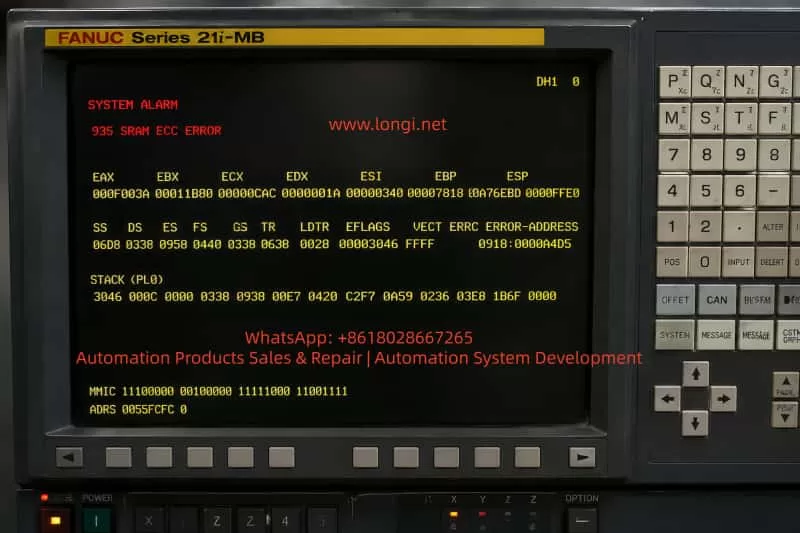
1. Introduction: Why Alarm 935 Must Be Treated as Critical
In FANUC CNC systems, 9xx-level alarms are not normal process-related faults. They indicate issues at the core control system level (CPU / memory / system software layer).
Among them:
935 SRAM ECC ERROR is a typical “data integrity collapse” failure.
This type of fault is characterized by:
CNC may still power on but cannot boot normally
Loss or corruption of parameters, PMC, or programs
Repetitive alarm after reboot
High risk of permanent system data loss if handled incorrectly
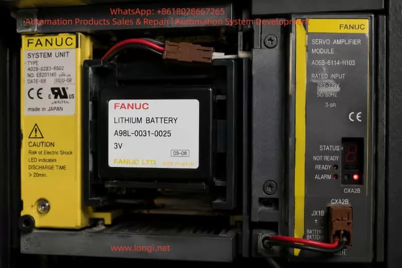
For legacy systems such as FANUC 21i-MB, this issue is particularly critical due to reliance on battery-backed SRAM storage.
2. Technical Meaning of Alarm 935
2.1 Role of SRAM in FANUC Systems
In FANUC CNC architecture, memory is divided into:
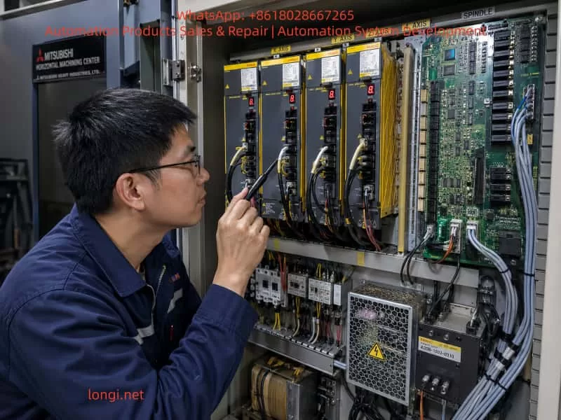
On CNC machines equipped with a FANUC 18M control system, the servo system is usually composed of a PSM power supply module, SVM servo amplifiers, spindle amplifier, motor feedback circuits, and the CNC-side serial servo interface. FANUC α series servo systems are generally reliable, but once a fault occurs in the control card, power card, IPM module, auxiliary power supply, or serial feedback chain, the alarm symptoms can overlap and mislead the repair process.
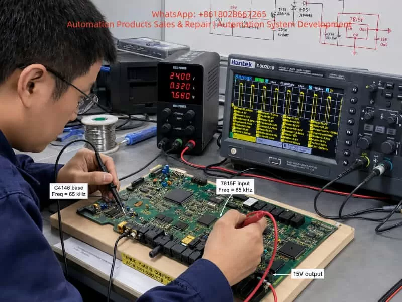
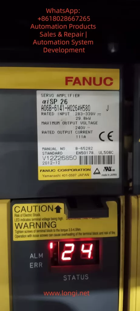
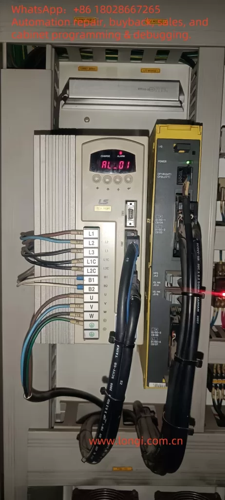
The case discussed here involves a horizontal machining center using a FANUC 18M CNC system. The machine is fitted with FANUC α series servo amplifiers. The Y-axis servo amplifier is A06B-6079-H106, and the control board is A20B-2001-093.
The reported symptoms include:
The Y-axis servo amplifier shows an 8-dot alarm on the seven-segment LED.
The CNC screen displays 414 SERVO ALARM: Axis Detect Error.
Another axis, such as B axis, also shows 351 SPC ALARM: Communication.
At first, the LED flickered, then the internal fuse blew, with a burnt smell.
A transistor marked C4148 on the control board was found shorted.
After replacing C4148, the fuse did not blow immediately, but once the power card was connected, the amplifier again showed 8-dot, and after several minutes the fuse blew again.
On the B-axis control card, when only 24V was supplied with the power card removed, the seven-segment LED showed a “-” sign. But after installing the power card, the “-” appeared briefly and then disappeared.
On the CNC diagnostic monitor, one or more axes were not detectable.
These symptoms should not be treated as a simple parameter problem, encoder fault, or servo initialization issue. The combination of repeated fuse blowing, burnt smell, seven-segment 8-dot alarm, damaged transistor, and failure after installing the power card strongly indicates a real hardware fault inside the servo amplifier.
The most likely fault area is the auxiliary switching power supply, power card load, IPM/IGBT drive circuit, current detection circuit, or servo communication detection circuit.
2. Meaning of “L Axis” in FANUC α Servo Amplifiers
When diagnosing FANUC α series servo amplifier alarms, the terms L axis, M axis, and N axis often appear in alarm descriptions. These terms can easily be misunderstood.
They do not necessarily refer to the actual machine axes such as X, Y, Z, B, or C. Instead, they refer to the internal amplifier channels.
Generally:
Servo amplifier type
Internal channel names
Single-axis SVM1 amplifier
L axis
Two-axis SVM2 amplifier
L axis and M axis
Three-axis SVM3 amplifier
L axis, M axis, and N axis
Therefore, if a single-axis amplifier is used for the machine Y axis, then the internal L axis of that amplifier is the machine’s Y axis.
For example, if the electrical cabinet arrangement is:
First module: PSM power supply module;
Second module: Y-axis single-axis servo amplifier;
Third module: X/Z two-axis servo amplifier;
Fourth module: spindle amplifier;
Then an 8-dot alarm on the second amplifier means the L-channel fault of that particular Y-axis amplifier. It does not mean that the machine has a separate “L axis”.
For the X/Z two-axis amplifier, the internal L and M channels must be identified by checking the motor power cable, feedback cable, CNC parameter assignment, and amplifier channel wiring. It cannot be judged only from the physical cabinet position.
This distinction is important. Otherwise, repair technicians may misinterpret “L axis” as the left-side module, left-side machine axis, or a nonexistent axis, causing the diagnosis to go in the wrong direction.
3. Relationship Between 414 Alarm and 351 Alarm
The FANUC 18M alarm 414 SERVO ALARM: Axis Detect Error is a broad servo detection alarm. It does not point to only one specific component. It means the CNC has detected a serious servo-related abnormality for one axis.
Possible causes include:
Internal overcurrent in the servo amplifier;
IPM or IGBT module abnormality;
Current detection circuit fault;
DC link voltage detection fault;
Servo amplifier control power supply abnormality;
Amplifier initialization failure;
Serial communication failure between CNC and servo amplifier;
Encoder feedback communication fault;
Mismatch between CNC parameters and actual servo hardware;
Failure of an upstream servo module affecting downstream detection.
The 351 SPC ALARM is usually related to serial pulse coder communication. Common causes include encoder cable failure, encoder damage, servo feedback interface fault, or CNC-side feedback communication abnormality.
In many actual repair cases, 414 and 351 appear together. This does not always mean the encoder itself is defective. If the control power supply of a servo amplifier is unstable, or if the servo communication chain is interrupted, the CNC may fail to detect downstream axes correctly and then generate both 414 and 351 alarms.
In a FANUC α servo system, several servo amplifiers may be connected in a communication chain. If the Y-axis amplifier has unstable control power, faulty serial communication, or a failed internal power supply, the following X/Z or B-axis amplifier may also become undetectable on the CNC screen. Therefore, a Z-axis or B-axis detect error does not automatically mean that the Z or B servo amplifier is the original fault.
The correct approach is to first repair or isolate the amplifier with obvious hardware failure, especially if it shows 8-dot, blows fuses, has burnt smell, and has damaged components.
4. Core Interpretation of the Y-Axis 8-dot Alarm
In this case, the Y-axis servo amplifier shows an 8-dot alarm and repeatedly blows the fuse. In FANUC α series servo amplifiers, 8-dot is typically related to inverter, IPM, overcurrent detection, or power drive section abnormality.
Although the exact meaning can vary depending on the amplifier generation and hardware version, the actual symptom combination is more important than the alarm code alone.
The key facts are:
The LED initially flickered;
The fuse blew;
There was a burnt smell;
C4148 on the control board was shorted;
After replacing C4148, the amplifier still showed 8-dot when the power card was installed;
The fuse blew again after a few minutes;
The waveform around C4148 showed high-frequency switching pulses;
The fault became worse only after the power card was connected.
These facts indicate that C4148 is unlikely to be the root cause. If C4148 were the only faulty component, replacing it should have restored stable operation. But the fault returned after installing the power card, which means the downstream load or related circuit is still abnormal.
A more reasonable conclusion is:
C4148 is being damaged by an abnormal load, short circuit, overvoltage spike, or switching power supply stress caused by the downstream power card or drive circuit.
The main suspect areas should therefore include:
Power card;
IPM / IGBT module;
Gate drive supply;
Current detection circuit;
Protection feedback circuit;
Secondary rectifier and filter circuit of the switching power supply;
Zener diodes and clamp diodes;
Optocoupler feedback circuit;
Connector interface between the control card and power card.
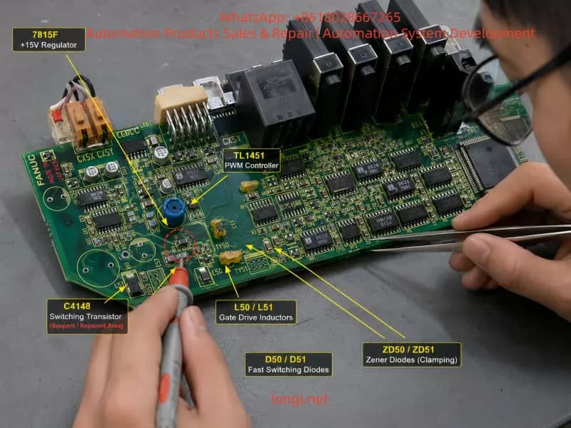
5. Analysis of the C4148, 7815F, and TL1451 Circuit
The hand-drawn circuit shows several important components: TL1451, 7815F, C4148, TR50, TR52, TR53, L50, L51, ZD50, ZD51, D50, D51, PM50, and PM51. Combined with the oscilloscope waveform, this area is not a simple static logic circuit. It is more likely a DC-DC auxiliary switching power supply or drive supply circuit on the servo control board.
5.1 Role of TL1451
TL1451 is a PWM controller. In a servo amplifier control board, it can be used to generate high-frequency PWM signals. These PWM signals drive transistors and magnetic components to produce multiple auxiliary supplies.
These auxiliary supplies may be used for:
IPM or IGBT gate drive;
Current detection isolation supply;
Protection and alarm detection;
Power card feedback;
Optocoupler isolation circuits;
Internal fault detection circuits.
The oscilloscope waveform showed that the base and emitter of C4148 had a pulse around 65 kHz. This matches the behavior of a PWM switching power supply. Therefore, TL1451 is at least oscillating, and the drive stage is working.
However, PWM waveform presence does not mean the power supply is healthy. If the secondary rectifier, filter capacitor, zener clamp, optocoupler feedback, or power card load is abnormal, TL1451 may continue to output PWM until the transistor, fuse, resistor, or another protection component fails.
5.2 Condition of 7815F
The measured waveform shows that the 7815F input is around 24V, and the output is around 15V. Both are relatively stable.
This indicates that the 24V-to-15V linear regulator stage is basically working at the moment of measurement.
If 7815F were the main faulty component, typical symptoms would include:
No 15V output;
Output voltage much lower than normal;
Large output ripple;
Voltage collapse after loading;
Severe heating of the regulator.
Since the 15V output is currently stable, 7815F should not be treated as the primary suspect. It is more likely providing supply voltage to TL1451 or nearby control circuits.
5.3 Meaning of the C4148 Waveform
The waveform on the base and emitter of C4148 shows a high-frequency pulse with about 30V peak-to-peak amplitude. If C4148 were used as a normal low-voltage transistor switch, such a waveform would be abnormal. A normal transistor base-emitter junction usually has about 0.6V to 0.8V forward voltage, and its reverse withstand voltage is limited.
Therefore, C4148 is probably located in a floating switching node, push-pull drive node, or transformer primary drive node.
Its failure may be caused by:
Excessive switching current due to downstream short circuit;
High leakage spike from a magnetic component;
Failed clamp diode or zener diode;
Cross-conduction in the transistor drive stage;
Abnormal PWM duty cycle;
Optocoupler feedback failure;
Power card auxiliary supply being pulled down;
IPM drive supply short circuit.
This also explains why replacing C4148 alone did not solve the fault.
6. Why the Fault Becomes Worse After Installing the Power Card
A key observation is that when the control card is powered alone, some voltages and waveforms can be established. But once the power card is installed, the Y-axis amplifier shows 8-dot and then blows the fuse. The B-axis has a similar pattern: the control card can display “-” with only 24V, but the display disappears after installing the power card.
This type of symptom usually means:
The power card or one of its connected loads is pulling down an auxiliary supply generated by the control board.
Possible causes include:
Short circuit in the IPM/IGBT drive circuit on the power card;
Shorted rectifier diode in the drive supply;
Leaky electrolytic or tantalum capacitor;
Shorted optocoupler or isolation amplifier;
Faulty current detection circuit;
Abnormal IPM alarm feedback line;
Leakage inside the IPM auxiliary terminal;
Contaminated, burnt, or bent connector pins between the control card and power card;
Low resistance on a 5V, 15V, 24V, or isolated drive supply line.
The fact that the fault becomes severe only after the power card is installed is very important. It means the repair should not stay only at the small components on the control board. If C4148, fuses, or resistors are replaced repeatedly without checking the power card load, the fault will return and may damage more parts.
7. Fuse Blowing Must Not Be Solved by Using a Thicker Fuse
In this case, the fuse was reportedly changed to “0.12 mm diameter × 2 strands”, and then it no longer blew immediately, but the amplifier still showed 8-dot.
This approach is risky.
The fuse is not only there to allow the machine to power up. Its function is to limit fault energy when a downstream circuit has a short. If a thicker fuse is installed without removing the fault, the result may be:
A small fault becomes a large burnt area;
The switching transistor fails again;
PCB copper tracks are damaged;
The IPM module receives secondary damage;
The CNC-side servo interface or communication circuit is damaged;
The short point becomes carbonized and harder to locate.
Therefore, when a fuse repeatedly blows, the correct solution is not to increase the fuse capacity. The correct procedure is to find the overcurrent branch using resistance measurement, diode-mode testing, current-limited supply injection, thermal inspection, and circuit isolation.
Only after the root cause has been removed should the original fuse specification be restored.
8. Recommended Diagnostic Procedure
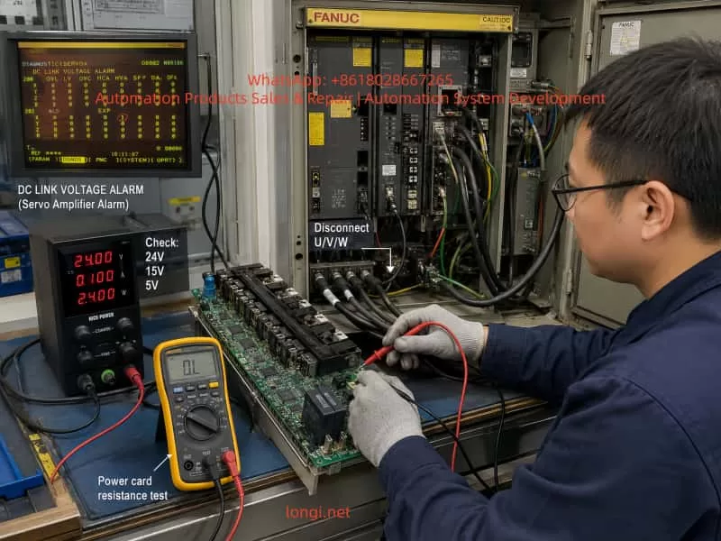
8.1 Disconnect Motor U/V/W First
The first step is to disconnect the Y-axis and B-axis motor power cables from the servo amplifiers, including U, V, and W.
This separates amplifier faults from motor, cable, or mechanical load faults.
The diagnostic logic is:
Test result
Interpretation
8-dot or fuse blowing still occurs with U/V/W disconnected
Internal amplifier fault is likely
Alarm disappears with U/V/W disconnected but returns when motor is connected
Motor, cable, or load-side fault is likely
Control power still collapses with the motor disconnected
Control card or power card auxiliary supply fault
Fault appears immediately when power card is installed
Power card or internal drive load short circuit
It is not recommended to continue energizing the amplifier before disconnecting the motor power cables.
8.2 Check Motor and Cable Insulation
The motor power cable insulation should be tested between:
U and PE;
V and PE;
W and PE;
U and V;
V and W;
W and U.
If the insulation to ground is low, or the three-phase resistance is unbalanced, the motor or cable may have an insulation breakdown.
Important warning:
Do not use a high-voltage megger on encoder cables, feedback cables, or communication cables. Doing so can damage the encoder and CNC feedback interface.
8.3 Check the IPM / IGBT Section
After full power-off and DC bus discharge, use a multimeter in diode mode or resistance mode to check:
P-N DC bus short circuit;
P-U, P-V, P-W;
N-U, N-V, N-W;
U/V/W phase-to-phase;
U/V/W to PE;
Braking circuit terminals, if applicable.
If one phase reads significantly different from the others, or if P/N to U/V/W shows near-short resistance, the IPM or IGBT module is highly suspect.
In that condition, further power-on testing may only cause more damage to the fuse, drive stage, or control board.
8.4 Check Control Board Low-Voltage Supplies
The following supplies should be measured carefully:
24V input;
15V regulated output;
5V logic supply;
TL1451 Vcc;
TL1451 reference voltage;
C4148 collector, base, and emitter;
ZD50 and ZD51 voltage;
Auxiliary supply lines at the power card connector.
Measurements should be taken under different conditions:
Power card removed;
Power card connected;
At the moment 8-dot appears;
Just before the fuse blows;
When the display disappears.
If the 15V or 5V collapses immediately after connecting the power card, the power card or its load is likely shorted. If the 24V current gradually increases and one component heats up, a thermal leakage fault may exist.
8.5 Measure Power Card Connector Resistance
With the machine powered off, discharged, and the power card removed, measure the resistance of the power card connector pins to 0V:
24V to 0V;
15V to 0V;
5V to 0V;
Drive auxiliary supply to its reference ground;
IPM alarm line to 0V;
Current feedback line to 0V;
Optocoupler supply line to 0V.
If one line reads only a few ohms or a few tens of ohms, follow that line to find the shorted component.
Common shorted parts include:
Tantalum capacitors;
Small electrolytic capacitors;
Zener diodes;
Rectifier diodes;
Gate driver ICs;
Optocouplers;
IPM internal auxiliary pins.
8.6 Use Current-Limited Power Injection
Repeatedly powering the amplifier from the machine supply is dangerous. A safer method is to inject voltage into the suspected branch using a current-limited bench power supply.
Suggested starting limits:
Supply branch
Injection voltage
Initial current limit
5V branch
3V to 5V
0.2A to 0.5A
15V branch
5V to 15V
0.1A to 0.3A
24V branch
12V to 24V
0.1A to 0.5A
After injecting voltage, check which component heats up. A thermal camera, infrared thermometer, alcohol evaporation method, or careful finger temperature check can be used.
If a zener diode, capacitor, driver IC, or optocoupler heats quickly, the shorted branch has likely been found.
8.7 Analyze the Failure Mode of C4148
After C4148 fails again, it should not simply be discarded. Remove it and test the failure mode:
Failure mode
Possible cause
Collector-emitter short
Excessive switching current, downstream short
Base-emitter short
Base drive overvoltage or reverse breakdown
Base-collector short
Switching spike or clamp failure
All three pins shorted
Severe overcurrent or overheating
Open circuit
Component burned open after transient breakdown
If the failure mode is the same each time, it can help identify the stress direction. For example, repeated collector-emitter shorting points to the main switching current path. Repeated base-emitter damage points to the base drive or clamp circuit.
9. Independent Analysis of the B-Axis Symptom
The B-axis control card can display “-” when only 24V is applied and the power card is removed. But after the power card is installed, the “-” appears briefly and disappears.
This is different from the Y-axis 8-dot symptom, but it still points toward a hardware power supply problem.
The fact that the control card can display “-” with only 24V means that at least part of the low-voltage logic can start. But when the power card is connected, the logic supply collapses or the control card shuts down.
Possible causes include:
Shorted power card;
Shorted connector between control card and power card;
Abnormal 5V, 15V, or 24V load on the power card;
Shorted drive supply or isolated supply;
IPM or gate driver IC internal short;
Feedback line abnormality causing protection shutdown.
Therefore, the B-axis fault should not be diagnosed as a parameter issue first. The correct direction is to check the power card, low-voltage loading, connector resistance, and auxiliary drive supply.
If a known-good board is used for cross-testing, all short-circuit checks must be completed first. Otherwise, a good control card or power card may be damaged by the same shorted load.
10. Chain Reaction of Axis Detect Errors
In FANUC 18M servo systems, the CNC communicates with the servo amplifiers through a defined serial chain. If an upstream servo module has abnormal control power or communication, downstream axes may also become undetectable.
Therefore, when the CNC displays Z-axis detect error or B-axis detect error, it does not always mean the Z-axis or B-axis amplifier is the original fault.
In this case, the Y-axis amplifier already has clear hardware fault evidence:
8-dot alarm;
Fuse blowing;
Burnt smell;
C4148 short circuit;
Fault returns when the power card is connected.
Therefore, the Y-axis amplifier should be treated as the first priority. After the Y-axis amplifier is repaired or isolated, the technician should check whether the X/Z or B-axis alarms remain. If the downstream axes become detectable again, the previous alarms were secondary communication effects. If the alarms remain, then the corresponding axis feedback cable, encoder, amplifier, and CNC parameter configuration should be checked separately.
11. Repair Strategy and Risk Control
For this type of FANUC α servo amplifier fault, the repair principle should be:
Isolate first, then power on. Measure shorts first, then waveforms. Use current-limited testing first, then full machine testing.
11.1 Practices to Avoid
The following actions are not recommended:
Repeatedly powering the amplifier directly on the machine;
Replacing the fuse with a thicker one;
Replacing only C4148 and continuing to test;
Judging the amplifier before disconnecting the motor;
Installing the power card before checking its resistance;
Using a high-voltage megger on encoder cables;
Swapping good and bad boards without short-circuit checks;
Treating fuse blowing and burnt smell as parameter faults.
11.2 Recommended Practices
The correct repair process should include:
Remove the faulty module for bench testing;
Restore the original fuse specification after repair;
Separate the control card, power card, and IPM for testing;
Compare resistance readings with a known-good axis card;
Measure TL1451-related supply and PWM signals;
Measure all power card interface supply lines to ground;
Find the downstream short before replacing C4148 again;
Perform no-load testing before connecting the motor;
Reconnect the motor only after 8-dot disappears;
Finally check whether CNC 414 and 351 alarms clear.
12. Practical Fault Location Map
For this kind of failure, the suspected areas can be divided into four levels.
Level 1: Control Board Auxiliary Supply
Components to check:
TL1451 PWM controller;
C4148 / TR53 switching transistor;
TR50, TR51, TR52 drive transistors;
7815F regulator;
ZD50, ZD51 zener diodes;
D50, D51 diodes;
L50, L51 magnetic components;
C57, C58, C59, C60, C61 capacitors;
PM50, PM51 optocouplers or feedback parts.
Possible faults:
PWM drive abnormality;
switching transistor overcurrent;
zener diode short;
filter capacitor leakage;
optocoupler feedback abnormality;
transformer or inductor winding fault.
Level 2: Power Card Load
Components or circuits to check:
5V/15V/24V load on the power card;
gate driver circuit;
IPM alarm feedback;
current detection circuit;
isolated power supply circuit;
connector pins;
power card electrolytic and tantalum capacitors.
Possible faults:
low-resistance short;
voltage collapse after connection;
thermal leakage;
optocoupler or driver IC short;
connector carbonization or contamination.
Level 3: IPM / IGBT Inverter Section
Check:
P-N;
P-U, P-V, P-W;
N-U, N-V, N-W;
U/V/W phase-to-phase;
U/V/W to PE;
braking circuit.
Possible faults:
internal IGBT short;
diode failure;
IPM alarm output abnormality;
phase output leakage;
drive supply short inside the module.
Level 4: External Motor and Cable
Check:
motor winding resistance;
insulation to ground;
power cable damage;
coolant/oil contamination in connectors;
mechanical load seizure;
brake release condition, if the axis has a brake.
Possible faults:
phase-to-ground leakage;
phase-to-phase short;
cable insulation breakdown;
connector contamination;
motor internal winding damage.
13. Final Conclusion
This fault is not a simple CNC parameter issue, nor is it a normal encoder communication problem. It is a hardware fault inside the FANUC α series servo amplifier that triggers a chain of servo alarms.
The Y-axis A06B-6079-H106 amplifier shows 8-dot, blows the fuse, produces a burnt smell, and damages C4148. The fault returns after the power card is installed. These symptoms strongly indicate that the real problem is located in the power card, IPM/IGBT drive circuit, auxiliary switching power supply, current detection circuit, or protection feedback circuit.
C4148 is only one damaged component in the fault path. It should not be treated as the root cause by itself.
The hand-drawn circuit and waveform analysis further show that C4148 belongs to a high-frequency auxiliary switching power supply controlled by TL1451. The 7815F regulator has approximately 24V input and 15V output, so the linear regulator itself is not the main suspect at this stage. The more important area is the downstream load of the TL1451 switching supply, including drive transistors, magnetic components, rectifier diodes, zener clamps, filter capacitors, optocoupler feedback, and the power card interface.
The B-axis symptom, where the control card shows “-” with only 24V but shuts down after installing the power card, also points to a power card or auxiliary supply load problem. It should be diagnosed as a hardware supply-loading fault before considering CNC parameters.
The CNC 414 and 351 alarms must be interpreted together with the actual amplifier condition. If one upstream amplifier has unstable control power or communication failure, downstream axes may also become undetectable. Therefore, the amplifier with the clearest hardware fault evidence should be repaired or isolated first.
The correct repair path is:
Disconnect motor U/V/W cables;
Check motor and cable insulation;
Measure IPM/IGBT bridge circuits;
Measure control board 24V, 15V, and 5V supplies;
Check TL1451 and C4148 switching supply behavior;
Measure power card connector resistance;
Use a current-limited bench supply to locate shorted branches;
Repair the downstream fault before replacing C4148 again;
Restore the original fuse specification;
Perform no-load testing first;
Reconnect the motor only after the 8-dot alarm disappears;
Finally verify that CNC 414 and 351 alarms are cleared.
Only this layered and isolated diagnostic method can prevent repeated fuse blowing, repeated C4148 failure, and further damage to the control board, power card, IPM module, or CNC servo interface. For aging FANUC α series servo amplifiers, this approach is safer and much closer to the real root cause than blindly replacing small components or randomly swapping modules.
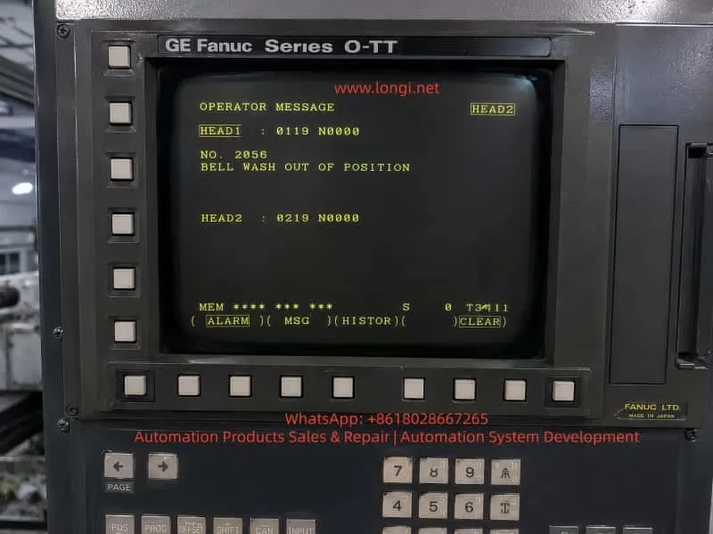
On a CNC lathe equipped with a GE Fanuc Series O-TT control, the operator screen may display an OPERATOR MESSAGE such as:
NO. 2056 BELL WASH OUT OF POSITION
The screen may also show channel-related information such as:
HEAD1 : 0119 N0000 HEAD2 : 0219 N0000
This indicates that the machine is most likely a twin-turret, twin-channel CNC lathe, not a simple single-channel turning machine. The alarm is not a standard Fanuc servo alarm, spindle alarm, or CNC main board alarm. It is a machine-builder PMC/operator message, generated by the ladder logic written for the machine’s peripheral mechanisms.
The key phrase is:
BELL WASH OUT OF POSITION
This can be understood as:
The Bell Wash mechanism is not in the correct position.
“Bell Wash” is not a universal Fanuc standard term. It is usually a machine-builder name for a washing, flushing, spraying, or cover-type cleaning mechanism. The word “Bell” may refer to a bell-shaped cover or a moving cleaning hood, while “Wash” refers to washing or flushing.
Therefore, this alarm should not be interpreted as a general coolant pump fault, spindle cooling failure, or Fanuc CNC control failure. The real meaning is that a certain washing mechanism has not reached the required home, retracted, extended, or safe position, or the PMC has not received the correct position confirmation signal.
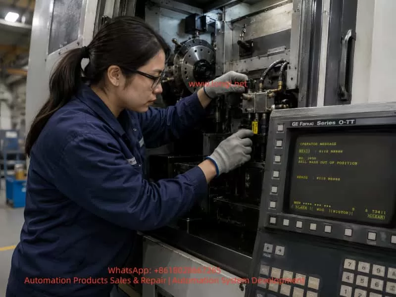
2. System Background: GE Fanuc Series O-TT
The GE Fanuc Series O-TT is commonly used on more complex CNC turning machines, especially those with:
Twin turrets;
Twin machining channels;
Upper and lower turrets;
One or two spindles;
Multiple hydraulic and pneumatic auxiliary mechanisms;
Automatic loading or unloading devices;
Workpiece washing or flushing systems;
Complex M-code controlled peripheral functions.
Compared with a simple single-turret lathe, a twin-channel machine has far more interlocks. One auxiliary mechanism may affect both channels. For example, if a washing cover is not retracted, it may prevent turret movement, spindle start, automatic cycle start, or work transfer.
This is why the screen may display HEAD1 and HEAD2 information. The fault may be related to one channel, or it may be a shared peripheral interlock that blocks both channels.
When diagnosing this type of alarm, the technician must consider:
Whether the alarm is associated with HEAD1 or HEAD2;
Whether the Bell Wash mechanism serves one channel or both channels;
Whether the machine is in manual, automatic, or interrupted cycle mode;
Whether the alarm blocks turret movement, spindle rotation, loading, or washing operation;
Whether both channels require a safe-position confirmation signal before the alarm clears.
3. Meaning of “BELL WASH OUT OF POSITION”
The term Bell Wash may refer to several possible mechanisms depending on the machine builder’s design:
A bell-shaped workpiece washing cover;
A chuck or spindle-area flushing mechanism;
A movable coolant or washing nozzle;
A cleaning arm driven by a pneumatic cylinder;
A washing unit used during automatic loading/unloading;
A cover or nozzle that must extend for washing and retract before machining;
A machine-builder-specific washing device with a custom name.
The important part of the message is OUT OF POSITION. This means the PMC does not see the required position state.
The expected position may be:
Home position;
Retracted position;
Extended washing position;
Safe position;
Cycle-ready position;
A valid combination of position sensor signals.
In most machines, the Bell Wash unit will have at least one position confirmation switch. Many designs use two switches:
Mechanism Status
Possible Sensor State
Bell Wash retracted / home
Home or retract sensor ON
Bell Wash extended / wash position
Forward or wash sensor ON
A typical two-sensor logic may be:
Bell Wash Status
Home Sensor
Forward Sensor
Retracted home position
ON
OFF
Extended wash position
OFF
ON
Stuck in middle position
OFF
OFF
Sensor logic abnormal
ON
ON
If the PMC expects the mechanism to be home but the home signal is missing, it may generate BELL WASH OUT OF POSITION. If the PMC commands the mechanism to the washing position but the forward signal does not appear, it may also generate the same message. If both sensors are ON at the same time, the ladder logic may judge the status as contradictory and raise an alarm.
4. Why This Is a PMC Interlock Alarm
This type of fault is normally controlled by the machine’s PMC logic.
The typical control sequence is:
CNC or PMC issues a command.
A PMC output drives a solenoid valve.
The solenoid valve actuates an air cylinder or hydraulic cylinder.
The Bell Wash mechanism moves.
A proximity switch or limit switch confirms position.
The signal returns to a PMC input.
The PMC confirms that the motion is complete.
The next machine step is allowed.
If any part of this sequence fails, the machine can report an operator message.
The fault chain includes:
Mechanical movement;
Pneumatic or hydraulic pressure;
Solenoid valve action;
Position sensor switching;
Wiring to the I/O module;
PMC input recognition;
Channel interlock logic.
This is why replacing Fanuc CNC boards or changing CNC parameters is usually the wrong first step.
5. Difference from a Chuck Jaw Sensor Alarm
A machine may previously have had a chuck jaw or chuck clamping sensor alarm. That type of fault and the Bell Wash alarm are different in component location, but similar in logic.
Mechanism stuck, low air pressure, sensor failure, wiring fault
Safety role
Chuck clamping confirmation
Mechanism clearance and cycle interlock
Both alarms belong to the same broad category: machine-side position confirmation faults.
The CNC is waiting for a position signal. If the signal is missing, wrong, or contradictory, the PMC stops the machine and displays an operator message.
6. Common Causes
6.1 Bell Wash Mechanism Not Returned to Home Position
The simplest cause is that the mechanism is physically out of position.
Possible reasons include:
Chips blocking the washing cover;
Coolant sludge around the sliding mechanism;
Deformed washing nozzle or cover;
A workpiece interfering with the washing unit;
A bent cylinder rod;
Dry or rusted guide rods;
Loose linkage;
Shifted mechanical stop;
Incorrect manual movement after maintenance;
Machine guard deformation.
In this case, the sensor and wiring may be normal. The problem is mechanical: the Bell Wash device has not actually reached the position required by the PMC.
The technician must inspect the actual mechanism before replacing electrical parts.
6.2 Low Air Pressure or Hydraulic Pressure
Many Bell Wash mechanisms are pneumatic because the motion is light, fast, and repetitive. If air pressure is low, the cylinder may move only partially and fail to reach the end position.
Possible pneumatic causes include:
Low main air supply;
Regulator pressure set too low;
Air valve not fully opened;
Air hose disconnected;
Bent or blocked air tubing;
Cylinder seal leakage;
Solenoid valve leakage;
Flow control valve closed too much;
Muffler blocked;
Water separator clogged;
Worn air cylinder.
If the mechanism moves slowly, stops halfway, or lacks force, the pressure system must be checked before the sensor circuit.
The same principle applies if the unit is hydraulically driven. In that case, check hydraulic pressure, solenoid valves, cylinder movement, oil level, filters, and leakage.
6.3 Solenoid Valve Not Switching
The Bell Wash unit is usually controlled by a solenoid valve. If the valve does not switch, the cylinder will not move.
Common causes include:
Burned solenoid coil;
No coil voltage;
Loose connector;
Sticking valve spool;
Contaminated valve body;
Faulty output relay;
No PMC output;
Blown fuse;
24 VDC supply problem.
Field checks include:
Observe whether the valve LED turns ON.
Listen for the clicking sound of the coil.
Measure voltage at the coil.
Press the manual override on the valve.
Watch whether the cylinder moves.
Check exhaust air from the valve ports.
If the mechanism works when the manual override is pressed, the air supply, valve body, and cylinder are probably functional, and the fault may be in the electrical command or PMC output. If the mechanism does not move even with manual override, check air supply, valve body, cylinder, and mechanical binding.
6.4 Misadjusted Position Sensor
The Bell Wash mechanism usually uses one or more position sensors, such as:
Inductive proximity switch;
Magnetic cylinder switch;
Mechanical limit switch;
Photoelectric sensor;
Microswitch.
These sensors are exposed to vibration, coolant, oil, chips, and occasional mechanical impact. A slight shift in sensor position can prevent the switch from detecting the target.
Typical symptoms include:
The mechanism appears to move correctly;
The alarm occurs intermittently;
The sensor LED is unstable;
The alarm disappears when the mechanism is pushed manually;
The alarm disappears after adjusting the sensor gap;
Vibration makes the alarm more frequent.
The sensor should be adjusted so that it is not at the edge of its detection range. After adjustment, the machine should be tested repeatedly.
6.5 Damaged Position Sensor
The sensor itself may also fail.
Typical symptoms include:
24 VDC supply is present but there is no output;
LED never turns ON;
LED remains ON all the time;
Output voltage does not change;
Signal changes when the cable is moved;
Sensor head is cracked or damaged;
Sensor face is covered with metal chips or oil sludge.
When replacing a sensor, the following specifications must match:
Voltage;
NPN or PNP output;
Normally open or normally closed logic;
Two-wire, three-wire, or four-wire type;
Sensing distance;
Thread size and mounting style;
Protection rating;
Cable type and wiring color.
Using the wrong sensor type may reverse the logic or make the alarm harder to diagnose.
6.6 Wiring or Terminal Fault
Older Fanuc machines often suffer from wiring faults in peripheral circuits. The Bell Wash unit is usually located near coolant, chips, and moving machine parts, so cables and connectors are vulnerable.
Common wiring problems include:
Broken sensor power wire;
Broken sensor output wire;
Loose 0 V common line;
Oil-contaminated connector;
Loose terminal strip;
Oxidized relay contact;
Loose I/O module connector;
Wrong reconnection after maintenance;
Damaged cable insulation.
The key diagnostic method is to compare three points:
Sensor LED condition;
Sensor output voltage;
Corresponding Fanuc PMC X input state.
If the sensor LED changes but the PMC input does not change, the signal is not reaching the CNC I/O. The technician must trace the wiring from the sensor to the terminal strip and then to the I/O module.
6.7 PMC Input or Output Fault
If the mechanism, valve, sensor, and wiring are confirmed good, then the I/O module or PMC control path should be considered.
Possible issues include:
Defective PMC input point;
Defective PMC output point;
I/O Link problem;
Interface board fault;
Common power supply problem;
Relay fault;
Fuse fault;
Incorrect keep relay condition;
Ladder condition not satisfied.
However, Fanuc board failure should not be the first assumption. In most real field cases, this type of alarm is caused by mechanical sticking, air pressure, sensors, valves, wiring, or terminals.
7. Diagnostic Procedure
Step 1: Confirm When the Alarm Appears
Record when the alarm occurs:
Immediately after power-on;
After reset;
During manual operation;
During automatic cycle start;
Before spindle start;
Before turret movement;
After an M-code command;
After washing operation;
In HEAD1 or HEAD2 operation.
If the alarm appears immediately after power-on, focus on the home/retracted signal. If it appears after a washing command, focus on the forward or completed-position signal. If it appears during automatic cycle start, focus on safe-position interlocks. If it appears in one channel only, check the relationship between HEAD1, HEAD2, and shared peripherals.
Step 2: Locate the Bell Wash Mechanism
Since “Bell Wash” is a machine-builder name, the physical unit must be identified on the machine.
Check these areas:
Chuck area;
Main spindle area;
Sub-spindle area;
Upper/lower turret area;
Workpiece transfer area;
Automatic loader area;
Machine door area;
Coolant flushing unit;
Small pneumatic cover or nozzle mechanism.
In the electrical drawings, look for terms such as:
BELL WASH;
WASH;
BW;
B.W.;
WASH HOME;
WASH EXTEND;
WASH RETRACT;
WASH POSITION;
IN POSITION;
CYLINDER;
SOLENOID.
Once located, inspect:
Cylinder;
Solenoid valve;
Proximity switch;
Limit switch;
Sensing target;
Mechanical stop;
Linkage;
Air or hydraulic tubing;
Cable route.
Step 3: Check for Mechanical Obstruction
With the machine in a safe condition, inspect whether the mechanism is stuck between positions.
Check for:
Chips;
Coolant sludge;
Workpiece interference;
Bent bracket;
Bent cylinder rod;
Damaged guide;
Loose linkage;
Worn sliding parts;
Impact damage;
Interference with turret, chuck, or guard.
If the mechanism is mechanically stuck, correct the mechanical fault first. Do not force the valve or repeatedly command the mechanism, because this may damage the cylinder, sensor, bracket, or surrounding components.
Step 4: Check Air or Hydraulic Pressure
If pneumatic, check:
Main air pressure;
Regulator pressure;
Air gauge;
Air shutoff valve;
Water separator;
Air hose;
Flow control valve;
Cylinder leakage;
Valve exhaust.
A normal pneumatic movement should be quick and positive. Slow or incomplete motion usually indicates pressure, leakage, or flow restriction.
If hydraulic, check:
Hydraulic pressure;
Oil level;
Filters;
Solenoid valve;
Cylinder stroke;
Leakage;
Return line restriction.
Step 5: Check the Solenoid Valve
Identify the solenoid valve that controls the Bell Wash mechanism.
Check:
Whether the valve LED turns ON when commanded;
Whether coil voltage is present;
Whether the valve clicks;
Whether manual override moves the mechanism;
Whether the cylinder moves fully;
Whether air exhaust changes.
Diagnostic interpretation:
Result
Likely Direction
Coil has voltage but valve does not move
Valve spool stuck, coil fault, air problem
Coil has no voltage but PMC output is ON
Wiring, relay, fuse, terminal issue
Coil has no voltage and PMC output is OFF
Ladder condition not satisfied
Manual override works
Air circuit and mechanism mostly OK; check electrical control
Manual override does not work
Check air supply, valve, cylinder, mechanical binding
Step 6: Check Position Sensors
Find the home and forward position sensors of the Bell Wash unit.
Observe sensor LEDs while moving the mechanism.
Typical logic:
Mechanism Status
Home Sensor
Forward Sensor
Retracted
ON
OFF
Extended
OFF
ON
Stuck halfway
OFF
OFF
Abnormal logic
ON
ON
If the mechanism is physically home but the home LED is OFF, check sensor distance, target position, sensor power, and sensor condition. If the LED is ON but the alarm remains, check PMC input. If both sensors are ON, check sensor placement, target design, or wiring short. If both sensors are OFF, check whether the mechanism is really between positions or whether sensor power is missing.
Step 7: Check Fanuc PMC Diagnosis
The most reliable electrical confirmation is to check the PMC input state.
The general operation path is usually:
Press SYSTEM.
Enter PMC.
Select PMCDGN or PMC DIAGNOSIS.
Display the related X input address.
Operate the Bell Wash mechanism.
Observe whether the input bit changes.
If the electrical drawings are available, use them to identify the exact X input address. Without drawings, an experienced technician can observe changing X bits while operating the mechanism, but this must be done carefully, especially on a twin-channel machine where many signals may change simultaneously.
8. Repair Methods
8.1 Clean and Restore the Mechanism
If chips or sludge block the mechanism:
Remove chips;
Clean coolant sludge;
Clean the guide;
Inspect nozzle and cover;
Lubricate sliding parts;
Repair bent brackets;
Confirm there is no workpiece interference;
Return the mechanism to its proper home position.
After cleaning, cycle the unit repeatedly.
8.2 Restore Air or Hydraulic Supply
For pneumatic systems:
Adjust air pressure;
Replace damaged air hoses;
Clean the water separator;
Adjust flow controls;
Repair air leakage;
Replace cylinder seals;
Replace faulty solenoid valves.
For hydraulic systems:
Check hydraulic pressure;
Check oil level;
Replace filters;
Check valve operation;
Repair leakage;
Confirm cylinder stroke.
8.3 Adjust Position Sensors
If the mechanism reaches position but the sensor does not switch:
Clean the sensor face;
Clean the sensing target;
Adjust the sensing distance;
Avoid edge-of-range adjustment;
Tighten the bracket;
Confirm stable LED switching;
Verify corresponding PMC input change.
Do not rely only on the LED. The signal must reach the PMC input.
8.4 Replace Defective Sensors
If the sensor is defective, replace it with the correct type.
Confirm:
Voltage;
NPN/PNP type;
NO/NC logic;
Wiring system;
Sensing distance;
Mechanical size;
Cable and connector style;
Protection rating.
After replacement, test both manual and automatic operation.
8.5 Repair Wiring
If the sensor output is good but PMC input is missing:
Tighten terminals;
Clean connectors;
Replace damaged cables;
Check intermediate relays;
Check I/O module terminals;
Measure 24 VDC and 0 V;
Confirm wire numbers;
Eliminate loose or intermittent connections.
8.6 Check I/O and PMC Signals
If all external components are good:
Check whether the PMC input responds;
Check whether the PMC output activates the valve;
Check I/O module power;
Check common terminals;
Check fuses;
Check relays;
Check connector condition;
Compare with known good input or output points.
PMC ladder modification should not be attempted without correct documentation and proper authorization.
9. Why Parameters Should Not Be Changed First
When BELL WASH OUT OF POSITION appears, the following actions should not be the first response:
Changing CNC parameters;
Initializing the control;
Clearing PMC data;
Replacing the Fanuc main board;
Permanently shorting sensors;
Bypassing the alarm;
Forcing automatic cycle;
Forcing spindle or turret movement.
This is a peripheral position interlock alarm. Bypassing it may allow a washing cover, nozzle, or cleaning arm to remain in the path of a turret, spindle, chuck, or workpiece. On a twin-channel lathe, that can cause serious mechanical collision.
Temporary signal simulation is only acceptable for controlled troubleshooting by qualified personnel, with the machine made safe and original wiring restored immediately after testing.
10. Special Considerations on Twin-Channel Lathes
A GE Fanuc Series O-TT machine can have complex synchronization between channels.
Important points include:
HEAD1 and HEAD2 relationship One mechanism may be commanded by one channel but required as a safe interlock by both channels.
M-code waiting logic One channel may wait for a Bell Wash complete signal while the other channel waits for synchronization.
Turret interference area If the Bell Wash unit is not retracted, it may block upper or lower turret movement.
Spindle and sub-spindle interlocks The washing mechanism may be related to chuck cleaning, work transfer, or sub-spindle handling.
Automatic loading/unloading If the machine has a loader, the Bell Wash position may be part of the loading sequence.
Signal stability Intermittent sensor signals may stop automatic operation even if manual operation appears normal.
After repair, the machine must be tested not only in manual mode but also in automatic operation, preferably with low-speed dry run and careful observation.
11. Post-Repair Verification
After repair, verify the complete sequence:
Reset the alarm.
Manually extend the Bell Wash mechanism.
Manually retract the Bell Wash mechanism.
Observe sensor LEDs.
Observe PMC input status.
Check cylinder movement speed.
Check for mechanical interference.
Perform a dry run.
Test HEAD1 operation.
Test HEAD2 operation.
Test related M-codes.
Confirm spindle, turret, and automatic cycle recovery.
Repeat several cycles to ensure stability.
If the alarm clears in manual mode but returns in automatic mode, check program sequence, M-code completion signals, PMC timers, and twin-channel synchronization logic.
12. Field Repair Conclusion
When a GE Fanuc Series O-TT twin-channel lathe displays:
NO. 2056 BELL WASH OUT OF POSITION
the most likely meaning is:
The Bell Wash washing mechanism is not in the position required by the CNC/PMC, or the correct position confirmation signal is not reaching the PMC input.
This is not normally a Fanuc CNC main board fault. It is not a standard coolant pump alarm. It is not necessarily a spindle cooling problem.
The most likely fault points are:
Bell Wash mechanism blocked by chips, sludge, or a workpiece;
Washing cover, nozzle, or arm not returned home;
Low air pressure causing incomplete cylinder movement;
Solenoid valve not switching;
Cylinder leakage or sticking;
Home or forward position sensor misadjusted;
Proximity switch or limit switch damaged;
Sensor cable broken or terminal loose;
PMC input not receiving the signal;
Twin-channel interlock condition not satisfied.
The correct troubleshooting method is to start from the physical mechanism, then check air or hydraulic supply, solenoid valve, sensors, wiring, and PMC inputs.
13. Summary
BELL WASH OUT OF POSITION is a typical peripheral mechanism position alarm on older twin-channel Fanuc CNC lathes. The key diagnostic point is not the CNC control itself, but the relationship between the washing mechanism and the PMC interlock logic.
The correct principle is:
First confirm whether the mechanism is physically in position. Then confirm whether the sensor detects that position. Finally confirm whether the PMC receives the signal.
The practical sequence is:
Locate the Bell Wash mechanism.
Check for mechanical blockage.
Check air or hydraulic pressure.
Check the solenoid valve.
Check position sensors.
Check wiring.
Check Fanuc PMC inputs.
Verify both HEAD1 and HEAD2 automatic operation.
A reliable repair must restore the real movement and true position feedback of the Bell Wash mechanism. Long-term bypassing, shorting, or disabling the alarm is unsafe, especially on a twin-turret/twin-channel lathe where one misplaced auxiliary device can cause turret collision, spindle interference, or automatic cycle failure.
In CNC lathe maintenance, Fanuc system alarms and machine-builder custom alarms are often confused. When an alarm appears on the CNC screen, many technicians first suspect the CNC control, servo amplifier, spindle drive, system parameters, or encoder feedback. However, a large percentage of lathe alarms are not caused by the Fanuc control itself. They are generated by the machine builder through the PMC ladder logic.
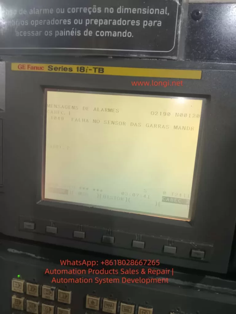
A typical example is a GE Fanuc Series 18i-TB CNC lathe displaying the following Portuguese alarm message:
1049 FALHA NO SENSOR DAS GARRAS MANDR
This can be translated as:
1049: Failure in the chuck jaw sensor
or more specifically:
Abnormal detection of the spindle chuck clamping/unclamping position sensor.
The Portuguese terms can be understood as follows:
FALHA means fault or failure. SENSOR means sensor. GARRAS means jaws or clamping jaws. MANDR is most likely an abbreviation of mandril, meaning chuck, mandrel, or clamping device.
Therefore, this alarm does not primarily indicate a damaged Fanuc CNC main board, servo axis fault, or spindle amplifier failure. The key fault area is the machine-side chuck clamping detection circuit, especially the chuck jaw sensor, hydraulic chuck position detection, and the PMC input logic.
On a CNC lathe, chuck clamping confirmation is a critical safety interlock. If the control cannot confirm that the workpiece is securely clamped, the machine may inhibit spindle rotation, block automatic cycle start, or stop the machine with an alarm. This prevents dangerous situations such as workpiece ejection, chuck accidents, and serious injury.
2. Meaning of the Alarm
The Fanuc 18i-TB is a widely used CNC control for turning machines. It controls axis movement, spindle commands, program execution, operator interface, diagnostics, and CNC functions. However, many auxiliary machine actions are not defined only by the Fanuc CNC software. Functions such as the hydraulic chuck, turret, tailstock, lubrication, door lock, hydraulic unit, coolant pump, chip conveyor, and safety interlocks are usually controlled through the PMC ladder program written by the machine builder.
For this reason, an alarm number such as 1049 is normally a machine-builder custom alarm. The same alarm number may mean different things on different machines, even if both machines use a Fanuc 18i-TB control. In this case, the displayed alarm text clearly states:
FALHA NO SENSOR DAS GARRAS MANDR
This makes the fault direction clear: the problem is related to the sensor for the chuck jaws or chuck clamping device.
This alarm usually means that the PMC ladder is waiting for a specific input signal, but the expected signal is not present. Typical situations include:
The chuck is commanded to clamp, but the clamp confirmation sensor does not turn ON.
The chuck is commanded to unclamp, but the unclamp confirmation sensor does not turn ON.
Both chuck clamp and chuck unclamp signals remain OFF.
Both chuck clamp and chuck unclamp signals appear ON at the same time.
The internal/external clamping mode does not match the actual sensor logic.
The hydraulic cylinder does not reach its end position.
The sensor is damaged, the cable is broken, the 24 VDC supply is missing, or the PMC input point is defective.
Therefore, troubleshooting should focus on the machine-side chuck mechanism, hydraulic circuit, proximity switches, sensor wiring, and PMC input status, rather than immediately replacing Fanuc CNC boards.
3. Basic Logic of Chuck Position Detection on CNC Lathes
To diagnose this type of alarm correctly, it is necessary to understand how chuck position detection normally works on a hydraulic CNC lathe.
A standard CNC lathe uses a chuck at the front of the spindle. At the rear of the spindle, a hydraulic rotary cylinder drives a drawtube or drawbar. This drawtube moves the internal wedge mechanism of the chuck, causing the jaws to clamp or unclamp the workpiece.
To allow the CNC/PMC to know the chuck condition, the machine builder usually installs position detection sensors near the rear spindle hydraulic cylinder. These sensors detect the position of the drawtube, piston rod, detection ring, or metal target.
A common arrangement includes:
One proximity switch for chuck clamp confirmation.
One proximity switch for chuck unclamp confirmation.
One or more metal targets or sensing blocks.
A mounting bracket near the hydraulic cylinder or drawtube.
A signal cable routed back to the machine I/O unit.
In a normal two-sensor configuration, the logic is usually:
Chuck Status
Clamp Sensor
Unclamp Sensor
Chuck clamped
ON
OFF
Chuck unclamped
OFF
ON
If the PMC requests chuck clamping but does not receive the clamp sensor signal, it interprets the chuck as not clamped. If the PMC requests chuck unclamping but does not receive the unclamp sensor signal, it interprets the chuck as not unclamped. If both signals are ON or both are OFF, the ladder may treat this as an abnormal sensor state.
Some machines also support internal clamping and external clamping modes. In external clamping, the jaws move inward to grip the outside diameter of the workpiece. In internal clamping, the jaws move outward to grip the inside diameter. Because the hydraulic cylinder direction and the definition of “clamped” may be different between these two modes, an incorrect internal/external clamping selection can cause a false chuck sensor alarm.
4. Common Causes of the Alarm
4.1 Proximity Switch Position Shift
This is one of the most common causes. The proximity switches near the spindle rear hydraulic cylinder are exposed to vibration, oil mist, coolant, chips, and mechanical impact. Over time, the sensor bracket may loosen or the sensing gap may change. The sensor may still be electrically good, but it cannot reliably detect the metal target.
Typical symptoms include:
The chuck can physically clamp and unclamp.
Hydraulic movement sounds normal.
The sensor indicator LED sometimes turns ON and sometimes does not.
The alarm appears intermittently.
The machine works when cold but alarms after vibration or thermal expansion.
Slightly moving the sensor or bracket changes the alarm condition.
The alarm appears more often after maintenance near the spindle rear area.
The solution is to readjust the proximity switch position. The sensing gap should not be set at the maximum detection distance. It should have a safety margin. In many field cases, a gap of approximately 1–2 mm is a reasonable starting point, depending on the sensor model and target material. After adjustment, the technician should repeatedly clamp and unclamp the chuck to confirm stable switching.
4.2 Damaged Proximity Switch
Chuck position sensors work in a harsh environment. They are often exposed to oil contamination, coolant mist, metal chips, and vibration. Over time, the proximity switch or its cable may fail.
Typical signs of a damaged sensor include:
24 VDC supply is present, but the output never changes.
The sensor LED never turns ON.
The sensor LED remains ON all the time.
The output voltage is unstable.
The signal flickers when the sensor body is tapped.
The cable near the sensor head is cracked or oil-damaged.
The sensing face is damaged by metal contact.
The sensor works only when the cable is bent in a certain position.
When replacing the sensor, the technician must not select a replacement only by physical size. The electrical specification must be correct. Important parameters include:
Supply voltage, usually 24 VDC.
Output type: NPN or PNP.
Contact logic: normally open or normally closed.
Two-wire, three-wire, or four-wire type.
Sensing distance.
Thread size, such as M8, M12, or M18.
Shielded or unshielded construction.
Cable color and wiring standard.
If an NPN sensor is replaced with a PNP type, or a normally open sensor is replaced with a normally closed type, the sensor may appear to work locally but the PMC logic will be wrong. This can cause the alarm to remain active or create a reverse chuck status indication.
4.3 Insufficient Hydraulic Pressure
A chuck sensor alarm does not always mean the sensor is defective. In many cases, the chuck has not actually reached the required mechanical position. If the hydraulic cylinder does not complete its travel, the sensor will naturally fail to detect the correct position.
Hydraulic-related causes include:
Hydraulic power unit not running.
Low hydraulic pressure.
Low oil level.
Contaminated hydraulic oil.
Worn hydraulic pump.
Pressure relief valve set too low.
Solenoid valve not shifting.
Valve spool sticking.
Internal leakage in the rotary cylinder.
External oil leakage.
Faulty pressure switch.
Blocked filter or restricted oil passage.
If the chuck movement is slow, weak, noisy, or incomplete, the hydraulic system must be checked before adjusting sensors. Adjusting a sensor to compensate for incomplete hydraulic movement is unsafe and unreliable.
Chuck clamping pressure must be appropriate for the workpiece size, material, chuck type, machining load, and spindle speed. Too little pressure may cause workpiece slippage or ejection. Too much pressure may deform thin-wall parts or accelerate chuck wear. The goal is not to set maximum pressure, but to restore the correct pressure range required by the machine and process.
4.4 Mechanical Sticking of the Chuck
The chuck itself can also cause this alarm. Over long-term operation, chips, sludge, dried grease, and coolant residues can accumulate inside the chuck. The jaw guides, wedge mechanism, master jaws, and scroll or wedge surfaces may become tight or uneven.
Typical symptoms include:
Chuck movement sounds heavy or abnormal.
Clamp or unclamp speed becomes slow.
One jaw moves differently from the others.
The chuck works without a workpiece but alarms when clamping a workpiece.
The alarm appears after changing to a different workpiece diameter.
The alarm occurs when the jaw travel is near the end of its range.
The chuck requires unusually high hydraulic pressure to move.
Maintenance should include:
Removing the jaws.
Cleaning jaw grooves and serrations.
Removing chips and hardened grease.
Inspecting wedge and sliding surfaces.
Checking the drawtube connection.
Lubricating with proper chuck grease.
Confirming that jaw travel is not at the mechanical limit.
Checking the rotary cylinder stroke.
If the chuck is badly worn, heavily contaminated, or mechanically damaged, it should be rebuilt or replaced. A chuck is a high-risk rotating clamping device. It should not be forced into operation by bypassing sensors.
4.5 Wiring or Terminal Contact Fault
Sensor wiring problems are also very common on older CNC lathes. Cables near the spindle rear area are exposed to vibration, oil, coolant, and mechanical movement. They may develop intermittent open circuits, insulation failure, connector contamination, or broken conductors inside the cable sheath.
Common wiring faults include:
Broken sensor power wire.
Loose 0 V common wire.
Broken output wire.
Oil-contaminated connector.
Loose terminal strip.
Damaged cable insulation.
Oxidized relay contact.
Poor contact at the I/O module connector.
Incorrect reconnection after maintenance.
The key diagnostic method is to compare the signal at three points:
The LED indication on the sensor body.
The voltage change on the sensor output wire.
The corresponding input bit in the Fanuc PMC diagnosis screen.
If the sensor LED changes normally but the PMC input does not change, the problem is usually between the sensor output and the CNC I/O input. This includes cable, terminals, intermediate connectors, relays, interface boards, or the I/O module.
4.6 Defective PMC Input Point or I/O Module
Although less common than sensor or wiring faults, a defective PMC input point can also cause this alarm. The Fanuc 18i-TB usually receives external machine signals through an I/O unit, I/O Link module, or machine-side interface board. If an input point is defective, the external sensor may output correctly, but the control will not recognize the change.
Diagnostic methods include:
Measuring the voltage directly at the I/O input terminal.
Observing the corresponding X input bit in the PMC diagnostic screen.
Comparing with adjacent input points.
Temporarily testing the sensor signal on a known good input point.
Checking I/O module power.
Checking the common terminal.
Inspecting the connector between the I/O board and CNC system.
If the input module is confirmed defective, replacement may be required. In some cases, a spare input point can be used, but this requires a correct ladder modification. PMC changes should only be performed by personnel who understand the original ladder logic and have the machine documentation.
4.7 Incorrect Internal/External Clamping Mode
Many CNC lathes allow selection between internal clamping and external clamping. In external clamping, the jaws clamp inward on the outside of the workpiece. In internal clamping, the jaws expand outward into the bore of the workpiece. The hydraulic cylinder movement and the meaning of “clamped” may be reversed depending on the machine design.
If the clamping mode is selected incorrectly, the machine may physically grip the workpiece, but the PMC may judge the sensor state as invalid.
Checks should include:
Confirming whether the current operation uses internal or external clamping.
Checking the clamping mode selector switch.
Confirming jaw installation direction.
Checking related PMC inputs or keep relays.
Reading the machine manual for chuck sensor logic.
Confirming which sensor should be ON after clamping in the selected mode.
This issue is especially common after chuck jaw replacement, soft jaw machining, maintenance work, or operator shift changes.
5. Field Diagnostic Procedure
Step 1: Record the Alarm Message and Operating Condition
The technician should first record the exact alarm number, alarm text, machine mode, and the moment when the alarm occurs. In this case, the alarm message points directly to the chuck jaw sensor, so the alarm should be treated as a machine-side PMC alarm.
Important questions include:
Does the alarm appear immediately after power-on?
Does it appear when clamping the chuck?
Does it appear when unclamping the chuck?
Does it appear when starting the spindle?
Does it appear when starting automatic cycle?
Does it appear during machining?
Did it start after maintenance?
Did it start after changing jaws or workpiece size?
The timing of the alarm provides a strong clue. If it appears during clamping, focus on the clamp confirmation signal. If it appears during unclamping, focus on the unclamp confirmation signal. If it appears only when starting the spindle, focus on the chuck clamp safety interlock.
Step 2: Manually Operate the Chuck
The next step is to operate the chuck manually and observe actual mechanical movement. The technician should not rely only on the screen or solenoid valve sound. The physical movement of the chuck jaws and rear hydraulic cylinder must be confirmed.
Check the following:
Does the chuck clamp?
Does the chuck unclamp?
Do the jaws move smoothly?
Is there a delay?
Does the hydraulic cylinder move fully?
Does the hydraulic pressure change?
Is the workpiece held securely?
Does the movement reach the end position?
If the chuck does not move at all, troubleshooting should shift toward the hydraulic power unit, solenoid valve, foot switch, interlock conditions, and control circuit. If the chuck moves normally but the alarm remains, the focus should shift to sensors and input signals.
Step 3: Check the Hydraulic Unit and Pressure
Hydraulic pressure is essential for reliable chuck operation. If the pressure is too low, the sensor alarm may be a consequence rather than the root cause.
Check:
Whether the hydraulic motor is running.
Oil level.
Oil temperature.
Hydraulic pressure gauge reading.
Chuck clamping pressure setting.
Solenoid valve coil status.
Valve shifting action.
Oil leakage.
Rotary cylinder internal leakage.
Filter blockage.
If hydraulic pressure is abnormal, the hydraulic system must be repaired first. Only after the chuck movement is mechanically correct should the sensor circuit be judged.
Step 4: Inspect the Sensors at the Rear of the Spindle
Open the rear spindle cover and locate the proximity switches near the chuck hydraulic cylinder. Usually there are two sensors: one for clamp confirmation and one for unclamp confirmation.
Observe the sensor LEDs while operating the chuck:
When clamped, the clamp sensor should turn ON.
When unclamped, the unclamp sensor should turn ON.
The two sensors should switch alternately.
They should not both remain ON.
They should not both remain OFF.
If the LED does not turn ON, check for 24 VDC supply. If supply is normal but the LED does not change, adjust the sensing distance. If adjustment does not help, replace the sensor. If the LED changes correctly but the alarm remains, continue with PMC input diagnosis.
Step 5: Check Fanuc PMC Diagnostic Inputs
One of the most reliable ways to troubleshoot this problem is to inspect the PMC input status directly.
On many Fanuc 18i-TB controls, the general path is:
Press SYSTEM.
Enter PMC.
Select PMCDGN or PMC Diagnosis.
Display the relevant X input address.
Clamp and unclamp the chuck.
Observe whether the corresponding input bit changes.
The exact soft key names may vary depending on the machine configuration. The machine electrical drawings should identify the I/O address for chuck clamp confirmation, chuck unclamp confirmation, clamping mode, pressure switch, and related safety interlocks.
If the electrical drawings are unavailable, an experienced technician may observe the X input area while operating the chuck and identify the changing bits. This method must be used carefully because multiple signals may change at the same time.
Step 6: Measure the Sensor Output Signal
When the sensor LED and PMC input do not agree, use a multimeter to measure the signal path.
Measure at:
Sensor power terminal.
Sensor output wire.
Intermediate junction box.
Terminal strip.
I/O module input terminal.
0 V common terminal.
For a common three-wire PNP proximity sensor:
Brown is usually +24 V.
Blue is usually 0 V.
Black is usually output.
When a PNP sensor is active, the black output wire usually switches close to +24 V. For an NPN sensor, the output is usually pulled toward 0 V when active. The actual wiring must always be confirmed against the machine circuit diagram.
6. Repair Methods
6.1 Adjust the Sensor Position
If the sensor is electrically good but does not detect reliably, adjust its position.
Procedure:
Clean the sensor face and metal target.
Loosen the sensor mounting nut.
Adjust the sensing gap.
Watch the LED switching point.
Avoid setting the sensor at the edge of detection.
Tighten the mounting nut.
Test repeated clamp/unclamp cycles.
Confirm stable PMC input switching.
After adjustment, test under realistic operating conditions. Vibration during spindle operation should not cause signal flicker. If vibration affects the signal, reinforce the bracket or replace the sensor with a more suitable type.
6.2 Replace the Proximity Switch
If the sensor is defective, replace it with a compatible model.
After replacement, verify:
24 VDC supply.
Correct LED operation.
Correct output voltage.
Correct PMC input status.
Correct clamp/unclamp logic.
Alarm reset.
Spindle start interlock operation.
The repair is not complete just because the sensor LED turns ON. The CNC/PMC must also read the signal correctly.
6.3 Repair Cable and Terminal Problems
If the sensor output is normal but the PMC input does not change, repair the signal path.
Possible actions include:
Tightening terminal screws.
Cleaning oil-contaminated connectors.
Replacing damaged cables.
Repairing aviation plugs.
Checking wire numbers against drawings.
Checking the 0 V common line.
Inspecting I/O module connectors.
Re-routing cables away from moving parts.
Cable routing around the spindle rear area must be secure. The cable should not rub against rotating parts or sharp edges.
6.4 Repair the Hydraulic System
If the chuck does not reach its position, repair the hydraulic system.
Typical work includes:
Refilling hydraulic oil.
Replacing contaminated oil.
Cleaning or replacing filters.
Adjusting chuck pressure.
Checking the hydraulic pump.
Checking solenoid valves.
Cleaning valve spools.
Inspecting the rotary cylinder seals.
Repairing oil leaks.
After hydraulic repair, chuck clamping force must be verified. A machine that no longer alarms but has weak chuck force is still unsafe.
6.5 Clean and Service the Chuck
If mechanical sticking is found, service the chuck.
Recommended work includes:
Removing jaws.
Cleaning jaw slots.
Cleaning serrations.
Removing chips and hardened grease.
Inspecting wedge and sliding surfaces.
Lubricating with correct chuck grease.
Checking drawtube connection.
Confirming full jaw stroke.
Checking the rotary cylinder stroke.
A worn or damaged chuck should be professionally rebuilt or replaced. Bypassing sensors to continue using a faulty chuck is unsafe.
7. Safety Precautions
A chuck sensor alarm must not be permanently bypassed. Some technicians may short the clamp confirmation signal to allow the machine to run temporarily. This practice is dangerous.
The chuck clamp confirmation signal may participate in:
Spindle start permission.
Automatic cycle start permission.
Hydraulic clamp confirmation.
Door safety logic.
Tailstock interlock.
Robot or bar feeder interlock.
Loader/unloader safety sequence.
If the signal is bypassed, the spindle may start even when the workpiece is not properly clamped. At high speed, this may result in workpiece ejection, machine damage, and serious injury.
Temporary signal simulation is acceptable only for controlled diagnosis by qualified personnel, and only under strict conditions:
Spindle disabled.
Workpiece removed.
Speed command set to zero.
Personnel away from the danger zone.
Original wiring restored immediately after testing.
A proper repair must restore real and stable chuck position detection.
8. Case Summary
For the GE Fanuc Series 18i-TB CNC lathe displaying:
1049 FALHA NO SENSOR DAS GARRAS MANDR
the most reasonable diagnosis is:
The chuck jaw sensor or chuck clamping/unclamping detection signal is abnormal. The PMC does not receive the correct chuck status confirmation signal.
The most likely fault points are:
Misadjusted clamp/unclamp proximity switch near the rear spindle hydraulic cylinder.
Manually operate the chuck and confirm mechanical movement.
Check hydraulic pressure.
Inspect the clamp/unclamp sensor LEDs.
Adjust sensor position.
Measure sensor power and output.
Check the related X input in the Fanuc PMC diagnosis screen.
Inspect cable, terminals, and I/O module.
Repair hydraulic or mechanical problems if movement is incomplete.
After alarm reset, test chuck operation and spindle interlock repeatedly.
9. Post-Repair Verification
After repair, the technician should not judge success only by the disappearance of the alarm. A complete functional test is necessary.
Recommended verification includes:
Clamp/unclamp test without workpiece.
Clamp test with workpiece.
Test with different jaw positions if applicable.
Low-speed spindle start test.
Medium-speed spindle running test.
Emergency stop and recovery test.
Automatic cycle start test.
Internal/external clamping mode check.
Repeated clamp/unclamp cycles.
PMC input stability confirmation.
The machine should be returned to production only when chuck movement is reliable, sensor signals are stable, hydraulic pressure is normal, and spindle safety interlocks function correctly.
10. Conclusion
When a Fanuc 18i-TB CNC lathe displays 1049 FALHA NO SENSOR DAS GARRAS MANDR, the fault is usually related to the chuck jaw sensor or chuck clamp/unclamp detection circuit. This is a typical machine-side PMC custom alarm, not a direct indication of Fanuc CNC board failure, servo drive failure, or parameter loss.
The correct diagnostic approach is to follow the chuck clamping chain step by step: hydraulic movement, mechanical travel, proximity switches, sensor wiring, and PMC input status. In field repair, the most common causes are misadjusted or damaged clamp/unclamp proximity switches near the rear spindle hydraulic cylinder, followed by low hydraulic pressure, mechanical chuck sticking, and wiring contact faults.
Chuck clamping detection is a critical safety function on CNC lathes. It must not be permanently bypassed, shorted, or disabled. A safe and reliable repair must restore true chuck status detection so that the CNC can correctly confirm clamping before allowing spindle rotation and automatic machining.
1. Introduction: When Replacing a CNC Controller Makes Things Worse
In FANUC CNC maintenance and retrofit projects, a very common but often misunderstood situation is the following:
The machine already had intermittent shutdowns or instability. After replacing the CNC controller, instead of being resolved, the system begins to generate multiple alarms, fails to start reliably, or completely loses power.
This article is based on a real FANUC CNC case involving a FANUC Series 0i-MC system used on a machining center. After replacing the CNC controller, the machine exhibited a clear alarm progression:
First power-on: SPM Alarm 24
After some operation: SPM Alarm 51
Subsequent power-on: SPM has no LED or display
CNC alarms simultaneously show:
9051 SPN: LOW VOLT DC LINK
433 X/Y/Z AXIS: CNV LOW VOLT DC LINK
Multiple spindle, APC, and serial communication alarms
Many technicians immediately suspect parameter mismatch, communication wiring, or controller incompatibility. However, a deeper engineering analysis shows that the root cause lies in the power system, not the CNC controller itself.
2. FANUC CNC Power Architecture: Why DC Link Matters
To correctly diagnose this type of failure, it is essential to understand FANUC’s power structure.
In a typical FANUC 0i-MC system with α or β series drives:
The PSM / SPM (Power Supply Module / Spindle Power Module):
Rectifies AC input
Generates the DC Link (DC Bus)
The Servo amplifiers (SVU/SVM):
Share the same DC Link with the spindle module
The CNC, I/O, and control circuits:
Depend on stable DC Link status and 24V control power
Key principle: If the DC Link collapses or becomes unstable, all axes and the spindle will be affected simultaneously. This is why multi-axis low-voltage alarms are extremely significant.
3. Alarm Classification: Root Causes vs. Consequences
The alarms observed in this case can be divided into three logical groups.
3.1 Core Alarms (Root Cause Indicators)
These alarms must be prioritized:
9051 SPN 1: LOW VOLT DC LINK
433 X / Y / Z AXIS: CNV LOW VOLT DC LINK
SPM Alarm 24
SPM Alarm 51
SPM panel has no LED or display
All of these point directly to DC Link voltage instability or failure.
3.2 Secondary Alarms (Triggered by DC Link Failure)
1400 SPINDLE ALARM
901 / 9012 SPN: OVERCURRENT POWER CIRCUIT
368 / 936 SERIAL DATA ERROR
These alarms typically occur when:
DC voltage becomes unstable
Power modules attempt to operate under abnormal conditions
Internal protection mechanisms are triggered
They are effects, not the primary cause.
3.3 Incidental Alarms (Not Related to the Root Cause)
1310 AIR LOW PRESSURE
300 APC ALARM: AXIS NEED ZRN
306 APC ALARM: BATTERY ZERO
100 PARAMETER WRITE ENABLE
These are normal maintenance-related or environmental alarms and should not distract from the main failure analysis.
4. Engineering Interpretation of SPM Alarm 24 and Alarm 51
4.1 SPM Alarm 24: Not Just a Communication Error
SPM Alarm 24 is frequently described as a communication or initialization issue between the CNC and spindle amplifier. While this can be true in isolated cases, it is not the most likely explanation when DC Link alarms are also present.
In real-world service cases, Alarm 24 commonly indicates:
DC Link pre-charge failure
DC bus voltage not reaching the required level
Pre-charge resistor or relay malfunction
Internal power supply operating at the threshold of failure
In other words, the communication symptom is secondary to a power establishment problem.
4.2 SPM Alarm 51: DC Link Has Entered a Critical State
SPM Alarm 51 explicitly indicates abnormal DC Link voltage conditions.
Typical engineering causes include:
Aging DC bus capacitors with increased ESR
Degraded rectifier bridge
Partially damaged IGBT modules
Unstable or low AC input voltage
At this stage, the power module is no longer capable of sustaining normal operation.
4.3 SPM Panel Has No LED: Hardware-Level Failure
When the SPM shows no LED or display:
Internal control power is no longer generated
Or the power stage has suffered catastrophic failure
This condition is not caused by CNC parameters, software, or wiring order. It indicates internal damage to the SPM module itself.
Repeated power cycling in this state often results in further damage.
5. Why Controller Replacement Appears to Trigger the Failure
This is one of the most misunderstood aspects of such cases.
Before replacement:
The machine already experienced frequent shutdowns
The power system was operating in a marginal or degraded condition
After replacement:
The new CNC controller follows a cleaner, more standardized startup sequence
Existing weaknesses in the power system are exposed immediately
The CNC controller does not cause the failure; it reveals it.
6. Reconstructing the Complete Failure Chain
From an engineering perspective, the event sequence is typically:
Power module aging or degraded components
Difficulty establishing stable DC Link voltage
SPM Alarm 24 (pre-charge or power establishment abnormality)
DC Link voltage drops further under load
SPM Alarm 51 (low DC voltage / power circuit abnormality)
Servo amplifiers report DC Link low voltage (Alarm 433)
CNC reports spindle DC Link alarms (Alarm 9051)
Internal SPM power supply or power stage fails
SPM panel no longer lights or responds
This sequence matches the observed alarms exactly.
Powering the system repeatedly under DC Link fault conditions accelerates damage to IGBTs, rectifiers, and capacitors.
Step 2: Verify 24V Control Power
If 24V control power is present but the SPM remains blank, internal module failure is highly likely.
Step 3: Inspect the DC Bus Physically
DC bus bars
High-current connectors
Contactors and fuses
Signs of overheating or loose connections
Step 4: Identify Exact Module Models
Recording the A06B-XXXX part numbers allows determination of:
Repair feasibility
Replacement options
Compatibility with the CNC system generation
8. Repair and Recovery Recommendations
Address the power modules first
SPM and PSM should be evaluated before any CNC parameter work
Assess the entire DC Link system
Power supply, bus wiring, and shared loads
Restore stable power conditions
Only then address APC alarms, batteries, and zero return
Verify parameters and communication last
This order minimizes downtime and prevents unnecessary part replacement.
9. Common Misdiagnosis Pitfalls
Assuming controller replacement is the root cause
Treating communication alarms as primary failures
Ignoring the significance of multi-axis DC Link alarms
Continuing to power a system with a non-responsive SPM
Avoiding these mistakes can save significant repair cost and time.
10. Conclusion
In FANUC CNC systems, the combination of:
SPM alarms
Multiple axes reporting DC Link low voltage
Frequent CNC shutdowns or OFF conditions
Almost always points to DC Link and power module failure, not CNC software or parameters.
Understanding the system-level power architecture and alarm relationships is the key to accurate diagnosis, efficient repair, and long-term system stability.
SEO Keywords (Naturally Integrated)
FANUC CNC FANUC Series 0i-MC SPM Alarm 24 SPM Alarm 51 LOW VOLT DC LINK FANUC spindle power module failure FANUC DC bus fault CNC controller replacement alarms FANUC CNC power supply troubleshooting
The Fanuc CNC (Computer Numerical Control) system is a core component in modern manufacturing, driving precise machining across industries from aerospace to automotive. These systems, such as the Series 0i-MD, rely on precision servo amplifiers, spindle modules, and control units to ensure high-speed, accurate operation. However, faults such as alarm codes SYS_ALM455 (indicating fan motor stop and system shutdown) and SPM 24 (serial data error) can disrupt production, leading to costly downtime. Based on real-world diagnostics, these alarms often relate to each other, with the failure of a DC bus connector exacerbating the issue.
This article offers a comprehensive technical exploration of these alarms in Fanuc systems, especially focusing on the βiSVSP amplifier series (e.g., model A06B-6164-H343). Based on the Fanuc maintenance manual and troubleshooting guides, we detail the causes, diagnostic methods, repair procedures, and preventive measures. The goal is to provide engineers and technicians with actionable insights to minimize faults and extend system lifespan, following a structured approach from symptom recognition to root cause analysis, ensuring efficient repairs and preventing recurrence.
1. Overview of the Fanuc CNC System
The Fanuc CNC architecture includes key components: the control unit (e.g., Series 0i-MD), servo amplifiers for axis control, spindle amplifiers (SPM) for rotation operations, and power supply modules (PSM). The βiSVSP series integrates the servo and spindle amplifiers into a compact unit, supporting multi-axis operation with high voltage capabilities up to 400V. For example, the A06B-6164-H343 model handles 40/40/80A servo current and 15kW spindle output, with a rated input of 200-240V AC at 50/60Hz.
Critical to the system’s reliability is the cooling mechanism, such as external or internal fans on the amplifier heat sinks, which dissipate heat from power transistors to prevent thermal shutdowns. Serial communication links the CNC controller to amplifiers via optical or electrical cables, ensuring synchronized data transmission of commands and feedback. Failures in these links or power distribution—such as through DC bus connectors (e.g., CX1A/B interface)—can cascade into alarms.
Understanding system interconnects is crucial: the DC bus links share power between modules, so loose connectors may underpower the fan or interrupt serial data, triggering SYS_ALM455 and SPM 24. Alarm logs with program counters (e.g., 10018B30H) and access addresses (e.g., 0100000AH) provide diagnostic clues, with timestamps (e.g., 2026/01/11 19:47:41) used for event correlation.
2. Alarm Code Analysis
SYS_ALM455: Fan Motor Stop and Shutdown
SYS_ALM455 indicates a cooling fan failure, prompting an immediate system shutdown to prevent damage from overheating of the amplifiers or motors. In the Fanuc Series 0i-MD, this alarm appears as “SYS_ALM455 FAN MOTOR STOP AND SHUTDOWN,” typically accompanied by a red LED on the amplifier.
Causes:
Fan Hardware Failure: Motor burnout, bearing seizure, or blockage from accumulated dust. Fans in the βiSVSP units (typically 24V DC, 40mm in size) are prone to wear after 20,000-50,000 hours of operation.
Power Issues: Fan circuit under-voltage due to DC bus fluctuations. Faulty main bus connectors (e.g., loose copper bars or oxidized pins) can drop the voltage below 22.8V DC, causing the fan to stop.
Environmental Factors: High ambient temperatures (>40°C) or poor ventilation increase thermal load, accelerating failure. Electromagnetic interference (EMI) from nearby motors can also disrupt fan control signals.
Software/Parameter Errors: Misconfigured parameters (e.g., No. 7310 for axis sequence) or checksum errors in the servo software, though rare in fan-specific alarms.
Diagnosis:
Visual Inspection: Check the amplifier LED (e.g., red ALM/ERR indicates a fault). Verify fan rotation by powering up the cabinet.
Voltage Measurement: Use a multimeter to measure voltage at the fan terminals; expect a stable 24V DC. Probe the DC bus (nominal 300V) for voltage drops.
Log Analysis: Review CNC diagnostics (Nos. 400-499) for serial status and temperature readings. Use an oscilloscope to check for EMI on cables.
Isolation Test: Disconnect the fan and test it independently. If it doesn’t rotate, the resistance between wires should be infinite.
If the alarm persists after power cycling, suspect an interconnect issue, such as a DC bus fault.
SPM 24: Serial Data Error
SPM 24 indicates a serial communication error between the CNC controller and the spindle amplifier module, shown as “24” on the SPM LED. It indicates data corruption or interruption, typically requiring a power cycle to reset.
Causes:
Communication Interruption: Noise on the serial cable (e.g., optical fibers or CX3/CX38 interface) from EMI, exceeding the maximum cable length (per B-65282EN manual), or poor grounding.
Power-Related Failures: CNC power loss during operation causing under-voltage on the SPM control PCB. Issues with main bus plugs—loose, damaged pins, or arcing—lead to unstable voltage, causing data parity errors.
Hardware Defects: Faulty SPM PCB, transistor modules, or feedback signals. In βiSVSP, this correlates with DC bus undervoltage alarms (e.g., Alarm 5: Low DC Voltage).
Cascading Effect: Often a secondary consequence of SYS_ALM455. The shutdown triggered by the fan failure disrupts power, resulting in SPM 24 as a “normal” response, but a persistent issue signals deeper problems.
Diagnosis logs may show “Serial Transfer Data Error,” with DGN No. 471 detailing spindle speed ratios or feedback mismatches.
Diagnosis:
Cable Inspection: Check for damage on the serial link. Test continuity and shielding. Use a logic analyzer to measure signal integrity.
Power Verification: Confirm AC input (200-240V) and DC bus (300V). Voltage fluctuations point to bus connector issues.
Parameter Review: Check Nos. 400-499 for communication status. Reset if noise is suspected.
LED Interpretation: SPM shows “-24” or “0 24” indicating specific sub-errors (e.g., cable fault vs. PCB issue).
3. Interlinking Alarms and DC Bus Issues
SYS_ALM455 and SPM 24 often occur together because they share a dependence on the DC bus. The main bus connector (copper bars or CX1 interface) distributes power; failures here lead to a cascade of alarms:
Voltage drops cause fan stoppage (SYS_ALM455).
Instability damages serial data (SPM 24).
In diagnostics, a loose connector manifests as intermittent alarms, exacerbated by vibration.
4. Fault Diagnosis Methodology
Effective diagnosis follows a logical, layered approach: symptom recording, isolation, and verification.
1. Initial Assessment:
Record alarm timestamps, program counters, and access data on the CNC screen.
Check the amplifier LED: red ALM indicates an error, blank display indicates a power failure.
Use Fanuc’s teaching pendant or MDI panel to access parameters.
2. Tools and Techniques:
Multimeter/Oscilloscope: For voltage, resistance, and waveform analysis.
Thermal Imaging: Detect hotspots on amplifiers or connectors.
Diagnostic Software: Fanuc’s PMC ladder logic viewer for signal tracking.
Isolation: Swap modules (e.g., test the fan on a separate power supply) to pinpoint the fault.
3. Step-by-Step Protocol:
Power Cycle: Reset alarms; if persistent, continue.
Component Testing: Fan (rotation test), cables (continuity), connectors (visual/torque checks).
Advanced: Monitor DGN parameters during operation to detect transient errors.
For βiSVSP, refer to the wiring diagram in B-65322. Document findings to identify patterns.
5. Repair Procedures
Repairs must prioritize safety: isolate power, use ESD protection, and follow OEM specifications.
For SYS_ALM455:
Fan Replacement: Locate fan on the amplifier heat sink (rear/top). Disconnect, remove (screws/clips), and install a new fan (e.g., A06B-6134-K002). Test rotation.
Cleaning: Use compressed air on the heat sink; avoid solvents on electronics.
Power Repair: If voltage is low, reset the DC bus plug; clean oxidation with isopropyl alcohol. Torque to specification (e.g., 2-3 Nm).
Verification: Power on, monitor for 30 minutes, and check diagnostics to clear.
For SPM 24:
Cable Repair: Replace faulty serial cables; ensure proper shielding/grounding.
PCB Replacement: If the PCB is suspected, replace the SPM control board (A20B-1009-0650 series).
Bus Connector Repair: Discharge the system, remove the plug, and check the pins. Clean/replace if damaged; reconnect securely.
Reset Sequence: Power down CNC and amplifier. Wait 5 minutes. Power on the amplifier first, then CNC.
Integrated Fix for Linked Alarms:
Address the root cause (e.g., bus plug): disconnect, test resistance (<1Ω), and reassemble.
After repairs: run spindle test (M03 S1000) and axis jog; monitor temperatures.
If the alarm recurs, escalate to Fanuc Service for PCB analysis.
Total repair time: 1-4 hours, depending on access.
6. Preventive Maintenance Best Practices
Proactive maintenance can reduce alarm frequency by 70-80%, based on industry benchmarks.
Daily/Weekly Routine:
Visual Inspection: Check fans, cables, and connectors for wear.
Cleaning: Remove dust from the cabinet; use intake filters.
Monitoring: Check CNC logs for temperature (e.g., spindle load table).
Monthly/Quarterly:
Voltage Audit: Measure input/output; calibrate if deviation >5%.
Fan Service: Lubricate bearings; replace every 2 years.
Cable Integrity: Torque check for bus plugs; validate EMI shielding.
Annual Overhaul:
Comprehensive Diagnostics: Use Fanuc tools for parameter backup, firmware updates.
Component Replacement: Batteries, fuses (e.g., F3 in PSM).
Training: Ensure operators follow the power-up sequence (amplifier before CNC).
Checklists: Daily (cleaning), 500 hours (check), 2000 hours (overhaul). Fanuc’s lifetime support and refurbished parts programs help control costs. Grounding to Class C standards prevents noise-induced errors.
7. Case Study: Resolving Interlinking Alarms in a Production Environment
In a recent scenario involving Fanuc Series 0i-MD and βiSVSP amplifiers, SYS_ALM455 and SPM 24 appeared simultaneously on 2026/01/11 at 19:47:41. Initial checks showed no fan rotation, with the DC bus voltage at 250V (below the nominal 300V). Diagnostics traced the fault to a loose main bus plug, causing undervoltage.
Fix: The system was powered off, and after cleaning, the plug was reset. The fan was independently tested (rotating at 24V). After repairs, alarms cleared, and spindle tests confirmed stable operation. Prevention: Added monthly torque checks and EMI filters. Downtime: 2 hours; prevented recurrence through planned maintenance.
This case highlights the value of comprehensive diagnostics, consistent with Fanuc’s B-65285EN manual recommendations.
Conclusion
SYS_ALM455 and SPM 24 showcase how interconnected Fanuc CNC components can lead to cascading faults, often stemming from power distribution issues like DC bus connectors. By mastering diagnostics (logs, tools), repairs (step-by-step), and prevention (routines), technicians can achieve >99% uptime. Always consult Fanuc manuals (e.g., B-65322, B-65282EN) and leverage OEM support for complex issues. Implementing these strategies not only resolves immediate problems but fosters long-term system resilience and optimized manufacturing efficiency.
The Fanuc αi series CNC system, as the core control platform for modern computer numerical control (CNC) machine tools, plays a crucial role in precision machining and automated production. This series integrates advanced servo amplifiers, pulse encoders, and fiber-optic communication technologies to ensure high-precision, high-speed axis motion control. However, system failures are inevitable during actual operation, with servo watchdog alarms (SYS ALM 426 SERVO WATCH DOG ALARM) and spindle servo amplifier alarms (ALM 124) being common issues. These faults often lead to system shutdowns, impacting production efficiency.
According to Fanuc’s official data, such alarms mostly stem from communication interruptions, hardware damage, or external interference. If not promptly diagnosed, they may trigger a chain reaction, such as axis runaway or motor overload. Based on the Fanuc αi series manuals (e.g., B-65282EN) and practical maintenance experience, this article systematically elaborates on the principles, causes, diagnostic methods, and maintenance strategies for these faults, aiming to provide comprehensive guidance for technicians. Through in-depth analysis, we will uncover the root causes of the faults and propose optimization measures to enhance system reliability and maintenance efficiency.
The Fanuc αi series servo system employs a serial communication architecture, including the FSSB (FANUC Serial Servo Bus) fiber-optic bus for data exchange between the CNC controller and servo amplifiers. This design improves anti-interference capabilities but introduces specific vulnerabilities, such as the physical integrity of fiber-optic cables. The ALM 426 alarm essentially triggers the system’s monitoring mechanism to prevent servo runaway caused by microprocessor hang-ups, while ALM 124 directly points to serial data transmission abnormalities in the spindle amplifier. Such faults account for 15%-20% of servo-related issues in global CNC applications, particularly in machine tools operating under high loads or in harsh environments. Understanding the triggering logic of these alarms is crucial for quickly restoring production. This article will commence with fault phenomena and progressively unfold the full diagnostic and maintenance process, ensuring technical depth and practicality.
2. Fault Phenomena and Alarm Code Interpretation
2.1 Description of SYS ALM 426 SERVO WATCH DOG ALARM
When the Fanuc αi series CNC system is powered on or during operation, if the screen displays “SYS ALM 426 SERVO WATCH DOG ALARM,” accompanied by diagnostic information such as the program counter (PROGRAM COUNTER), access address (ACCESS ADDRESS), and access data (ACCESS DATA), along with a prompt stating “THE SYSTEM ALARM HAS OCCURRED, THE SYSTEM HAS STOPPED,” it indicates that the system has entered a protective state. This alarm typically halts all axis movements and locks the CNC interface, preventing the execution of any commands.
From a hardware perspective, this is a system-level error involving the monitoring timer on the axis control card (Axis Control Card). The watchdog mechanism is a hardware/software-combined fault detector that monitors the CPU’s execution state by periodically resetting a timer. If the CPU fails to reset the timer within the specified time (e.g., due to a dead loop, memory error, or interrupt loss), the timer overflows, triggering the alarm.
Specifically for the αi series, diagnostic data such as the access address 010000802H often points to RAM parity errors (Parity Error) or pulse encoder feedback interruptions. The system log may display a timestamp, such as 2026/01/06 07:33:35, recording the moment of fault occurrence. This not only facilitates traceability but also allows correlation with environmental factors, such as power fluctuations or electromagnetic interference. In multi-axis systems, ALM 426 may only affect specific axes, but due to the global nature of the watchdog, it often results in a complete system blackout (Black Screen of Death). Compared to other Fanuc series (e.g., the 0i series), the αi series’ watchdog is more sensitive to serial bus stability because it utilizes high-speed fiber-optic communication, where even minor delays can be amplified into timeout errors.
2.2 Description of ALM 124 Spindle Servo Amplifier Alarm
The servo amplifier (e.g., aiSP 26 model, A06B-6114-H026#H580) displays “ALM 124” (or abbreviated as 124), indicating a serial communication error in the spindle module. This alarm typically occurs during power-on self-tests or warm-up cycles and is often accompanied by a联动 (linked) triggering of ALM 426 on the system side. The amplifier panel LED displays “124,” with the status indicator showing ERR (Error) instead of the normal STAT (Status).
In principle, ALM 124 detects abnormalities in serial data transmission between the CNC and the spindle amplifier, including data parity failures, frame losses, or timeouts. The Fanuc αi series spindle amplifiers use LSI (Large Scale Integration) chips to handle serial communication, and any abnormalities in the ROM (Read-Only Memory) or fiber-optic interface will trigger this alarm.
Unlike other amplifier alarms (e.g., ALM 1 for internal fan stop), 124 focuses more on communication layer issues. In real-world scenarios, even replacing the amplifier may not resolve the alarm if the root cause remains unaddressed. This reflects the systemic nature of the fault: spindle communication interruptions feed back to the CNC, inducing watchdog timeouts. According to Fanuc manual B-65285EN, subcodes of ALM 124 may include d2 (Serial Data Error) or d3 (Data Transfer Error), further refining problem localization.
These alarms exhibit strong linkage: ALM 124 acts as the trigger source, amplifying into the system-level ALM 426. Understanding the hierarchical structure of the alarm codes helps prioritize the investigation of peripheral components rather than blindly replacing core hardware.
3. Fault Cause Analysis
3.1 Hardware-Related Causes
Hardware failures are the primary诱因 (contributing factors) for such alarms, accounting for approximately 60% of cases. Firstly, issues with fiber-optic cables (Optical Fiber Cable, such as COP10A/B) are the most common. These cables are responsible for signal transmission via the FSSB bus, and loose connections, fractures, excessive bending (minimum bending radius > 50 mm), or end-face contamination can lead to signal attenuation or reflection, triggering serial communication errors. Fanuc stipulates that the insertion loss of fiber-optic cables should be < 1 dB, and any damage exceeding this value can trigger ALM 124. In harsh workshop environments, dust, oil, or mechanical vibrations further accelerate cable degradation.
Secondly, failures in the pulse encoder (Pulsecoder) or sensors on the spindle motor side are crucial. The encoder provides position feedback, and if there is an A/B phase shift, no pulse output, or serial data abnormalities (e.g., SP0132 error), the feedback loop is interrupted, leading to watchdog timeouts. Noise interference (Noise Interference) is another key factor: electromagnetic noise transmitted from power lines or nearby equipment can interfere with serial signals. Fanuc diagnostic numbers DGN 356/357 can monitor noise counts, and if the count exceeds 1000, it indicates excessively high environmental noise.
RAM parity errors on the axis control card are a direct cause of ALM 426. This card integrates the CPU and memory, and if radiation or aging causes bit flips, parity failures trigger the alarm. Additionally, damage to internal modules in the amplifier, such as the IPM (Intelligent Power Module) or ROM, can indirectly affect communication. Power supply issues cannot be overlooked: a low DC link voltage (< 300 V) or improper sequencing (CNC powering on before the amplifier) can induce initial communication failures.
3.2 Software and Parameter Configuration Causes
At the software level, parameter mismatches are a common issue. For example, incorrect settings for parameters 2557 (Amplifier Groups) or 3716#0 (Spindle Serial Output) can lead to incompatible communication protocols. If parameters are not reinitialized after replacing an amplifier, old configurations may conflict, triggering ALM 124. Improper backup of Fanuc system parameters (e.g., during battery replacement with a power interruption) can result in lost calibrations, further exacerbating faults.
Furthermore, inconsistent firmware versions are problematic: the ROM version of the αi series amplifier must match that of the CNC, and improper upgrades can lead to serial data format errors and alarms. Noise countermeasure parameters (e.g., filtering thresholds) that are not optimized can also indirectly cause timeouts. In multi-axis synchronous control, incorrect program commands (e.g., moving a slave axis) can induce watchdog alarms.
3.3 External Environment and Operational Factors
External factors include overheating, vibration, and contamination. Activation of the amplifier’s thermal switch (Thermal Switch) can interrupt communication, while high workshop humidity may lead to cable corrosion. Operational missteps, such as excessive pulling during cable installation or failure to adhere to the minimum bending radius, can also pose hidden risks. Fanuc emphasizes that fiber-optic cable handling requires specialized tools to avoid fingerprint contamination on end faces.
Globally, power fluctuations (e.g., unstable power grids) account for 10% of the causes, particularly in developing countries. Environments that do not meet electromagnetic compatibility (EMC) standards can amplify noise interference. Comprehensive analysis reveals that these causes often intersect: a loose cable may trigger a chain reaction leading to RAM errors.
4. Diagnostic Process
4.1 Preliminary Inspection Steps
Diagnosis begins with safely powering off the system: turn off the main power supply and wait 5-10 minutes for discharge. Visually inspect all cables: check if the fiber-optic COP10A/B cables are securely connected, free from bends or damage. Use a flashlight to test the fiber-optic cables: shine light into one end and observe the intensity at the other end; if dim, it indicates excessive attenuation. Clean the connector end faces using a lint-free cloth and isopropyl alcohol, avoiding cotton swab fibers.
After powering on, record the complete alarm log, including timestamps and access addresses. Enter MDI mode and press the diagnostic key to view DGN parameters: check DGN 356/357 for noise and DGN 409 to verify servo status. If noise levels are high, isolate high-power equipment. Perform a cable swap test: move the suspect cable to another axis; if the alarm shifts, confirm the cable fault.
4.2 Advanced Diagnostic Methods
Use Fanuc SERVO GUIDE software to analyze signal waveforms: connect a laptop and monitor the pulse encoder output. If the A/B phase shift exceeds 5%, replace the encoder. Use an oscilloscope to measure the DC link voltage, ensuring it falls within the 283-339 V range. Check the amplifier fuses (FU2) and polarity: a short circuit in the CXA2A/B cable can directly trigger ALM 124.
For ALM 426, inspect the axis control card: remove the card board and check for burn marks on the RAM chips. If a parity error occurs, use diagnostic tools to clear the registers, but if it recurs, replace the card board. Noise troubleshooting includes adding shielding covers and improving grounding (< 0.1 Ω resistance). In complex cases, refer to Fanuc manual B-65280EN to perform automatic parameter initialization.
Diagnosis should proceed layer by layer: start with peripherals (cables, power supply) and then move to core components (board cards, ROM). The average diagnostic time is 2-4 hours, depending on tool availability.
5. Maintenance Methods
5.1 Component Replacement and Repair
If cable faults are identified, replace them with original Fanuc fiber-optic cables (A66L-6001 series), ensuring the connection torque is 3.5-4.5 Nm. After replacing an amplifier (e.g., aiSP 26), verify that the serial number matches and reset the parameters. If the encoder is damaged, replace the entire motor assembly to avoid calibration loss from disassembly.
For RAM errors, replace the axis control card (A20B-3300 series) and transfer backup parameters. ROM damage requires professional burning or replacement of the amplifier PCB. For power supply issues, replace the rectifier module and ensure the AC input voltage is within the 283-339 V range.
5.2 Parameter Adjustment and Software Optimization
Enter parameter mode (press PROG + RESET) and modify relevant parameters: set parameter 4657 to match the amplifier group. For noise countermeasures, adjust filtering parameters (e.g., enable noise suppression with 2200#4). Upgrade the firmware using Fanuc tools to ensure version compatibility. Backup parameters using a CF card monthly.
5.3 Preventive Maintenance Strategies
Regular maintenance is key: inspect cable integrity monthly and clean connectors quarterly. Monitor temperatures below 50°C and avoid overloading. Implement EMC measures: separate control lines from power lines by > 30 cm. Train operators on proper cable handling to avoid pulling. Fanuc recommends annual professional audits using thermal imaging cameras to detect hot spots. Establish a maintenance log according to ISO 9001 standards to track fault patterns.
6. Case Studies
6.1 Case Study 1: Linked Alarms Triggered by Cable Fault
On a Doosan machine tool, ALM 426 and 124 appeared upon power-on. Initial inspection revealed excessive bending of the fiber-optic cable, causing a 30% signal attenuation. Replacing the cable resolved the alarms. Lesson learned: Adhere to bending radius specifications during installation.
6.2 Case Study 2: Persistent Fault Due to Noise Interference
After replacing the amplifier, the alarm recurred. Diagnosis showed a noise count > 5000. Adding shielding and improving grounding resolved the issue. Analysis: Nearby welding machines were interfering with the serial signals.
6.3 Case Study 3: Software Issue from Parameter Mismatch
After installing a new amplifier, ALM 124 appeared. Checking revealed that parameter 3716#0 was not set; adjusting it resolved the issue. Emphasis: Hardware replacement must be accompanied by software configuration.
These cases are sourced from real forum discussions, highlighting the systematic nature of diagnosis.
7. Conclusion
Diagnosing and maintaining servo watchdog alarms and communication faults in the Fanuc αi series require a multi-dimensional analysis of hardware, software, and environmental factors. Through the detailed principle interpretations, cause analyses, diagnostic processes, and maintenance methods presented in this article, technicians can efficiently address such issues and reduce downtime. In the future, with the integration of IoT, predictive maintenance will further lower fault rates. Adhering to best practices ensures long-term stable operation of the system.
This is one of the more common and serious errors in the Fanuc control system. Let’s analyze the causes and handling directions:
1. Alarm Meaning
SRAM ECC Error: The system has detected a checksum error in the SRAM memory.
ECC (Error Checking and Correction) is an error-detection mechanism. This alarm is triggered when data in the SRAM (battery-backed memory or system RAM) is corrupted.
The alarm code 935 generally indicates:
Corruption of SRAM data bits
Failure of the memory chip itself
Loss of data due to battery power failure or insufficient charge
2. Possible Causes
Damage to the SRAM chip on the motherboard (a common hardware aging issue)
Battery depletion or poor battery contact → Loss of SRAM data
Corruption of parameter files (caused by abnormal shutdowns or interference)
Failure of the control board itself (CNC Main Board)
3. Typical Symptoms
The system fails to start normally (as seen in your video, stuck at the alarm screen).
Repeated reboots may still result in the same alarm.
Occasionally, the system may boot, but all parameters are lost.
4. Solution Steps
A. Check the Battery
Open the control cabinet and locate the Fanuc SRAM backup battery (usually a lithium battery, 6V or 3V × 2 in series).
Measure the voltage. If it is < 5.6V (for a 6V battery) or < 2.9V (for a single 3V battery), it must be replaced.
When replacing, ensure the controller remains powered (to avoid data loss due to power failure).
B. Attempt to Clear SRAM and Reinitialize
Enter the system maintenance mode (BOOT/INITIALIZE).
Execute SRAM CLEAR (clear the memory).
Reload the PMC Ladder, system parameters, and machine parameters.
Requires backup parameters provided by the original machine tool manufacturer (important!)
C. If the Error Persists After Clearing
There is a high probability of a hardware failure in the motherboard’s SRAM.
The motherboard (CNC board/Memory Board) needs to be replaced.
Experienced maintenance engineers may attempt to replace the SRAM chip, but replacing the entire board is generally more reliable.
5. Recommended Immediate Actions for This Problem
First, check the battery voltage → If the battery voltage is low, replace the battery and attempt to power on again.
If the battery is normal → Enter maintenance mode, clear the SRAM, and reload the parameters.
If the error persists after clearing → It is likely a motherboard hardware failure, requiring repair or replacement.
⚠️ Note:
Clearing the SRAM will result in the loss of machine tool parameters. Always have a backup file (from a CF card, PC card, or obtained from the manufacturer).
Without parameter backups, even if the error is cleared, the machine tool cannot be restored to normal operation.
Applies to: Fanuc Series 0i‑TC CNC + S&T TNL‑120V vertical turning lathe. The turret axis uses an LS Mecapion APM‑SG20MKX1‑SNT servo motor driven by an APD‑VP20(SNT) servo amplifier. The motor is equipped with a TS5643N1 multi‑turn absolute encoder (2048 P/R).
Symptom: The internal lithium battery of the LS drive failed → drive raised AL‑14/AL‑15 absolute‑data/battery errors → the customer, suspecting a bad encoder, loosened the flexible coupling between encoder and motor → the encoder zero position no longer matches the motor’s electrical 0° → even after replacing the battery, absolute position is offset and the Fanuc CNC continues to alarm, rendering the machine inoperable.
Contents
System architecture & fault background
Relationship between absolute encoders and electrical 0°
Root‑cause chain analysis
Tools & safety preparation
Step‑by‑step restoration workflow 5.1 Replacing the drive battery 5.2 Mechanical realignment of the coupling 5.3 Drive parameter & menu operations 5.4 Rebuilding the reference point inside Fanuc
In‑depth explanations of key menus 6.1 PC‑806 Z POS Search 6.2 PC‑811 ABS Encoder Set 6.3 HSIN/HSOUT handshake for absolute data
Commissioning and verification
Preventive measures & maintenance tips
FAQ
Closing remarks
1 System Architecture & Fault Background
1.1 Machine configuration
Machine: S&T TNL‑120V vertical turning center with 8‑station turret.
Control: Fanuc Series 0i‑TC. Spindle and linear axes use standard FANUC α drives. The turret axis, however, is an LS Mecapion solution supplied by the OEM (S&T) for cost optimisation.
Turret servo package:
Drive: APD‑VP20(SNT) AC servo amplifier (200 – 230 VAC, 3‑phase).
Signal exchange with Fanuc is via dry‑contact and PMC bits for turret index, clamp/unclamp and axis ready.
1.2 Absolute‑backup battery
The APD‑VP20 houses a 3 V lithium cell (CR‑1/2AA or equivalent) that keeps encoder multi‑turn data and drive parameters alive. Low voltage triggers:
AL‑14 ABS Data Error
AL‑15 ABS Battery Error
AL‑16/17 Multi‑turn overflow
If the machine is powered with a dead battery the drive locks, Fanuc does not receive “Servo Ready” and the turret axis reports an alarm.
2 Absolute Encoders vs. Electrical Zero
Electrical 0° — the reference angle for vector control, aligned with the rotor magnetic poles.
Mechanical zero (Z‑pulse) — one pulse per revolution supplied by the encoder and factory‑aligned to electrical 0°.
Multi‑turn count — stores the number of revolutions, maintained by battery or Wiegand energy harvesting.
Any movement of the encoder housing with respect to the motor shaft (loosening the flex coupling, removing fixing screws, etc.) destroys that alignment → field‑orientation fails → over‑current or inability to find the Z pulse.
3 Root‑Cause Chain Analysis
Step
Trigger
Consequence
①
Battery dies
AL‑15, absolute data invalid
②
Encoder suspected faulty, coupling loosened
Encoder shifted relative to rotor
③
Re‑assembled randomly
Z‑pulse no longer equals electrical 0°
④
Battery replaced but no calibration
Drive still alarms, cannot Servo‑On
⑤
CNC continues to alarm
Turret cannot index, machine down
4 Tools & Safety Preparation
3 V CR‑1/2AA lithium cell (original or Panasonic welded type).
Phillips and Allen keys, torque driver.
Manual pulse generator (MPG) or low‑speed jog via PLC panel.
Insulated gloves, multimeter, oscilloscope (optional to watch Z‑pulse).
LS Loader PC utility + RS‑232 cable (optional).
Wait 5 minutes after power‑off until the ‘CHARGE’ LED is out (< 50 V DC bus) before opening the cabinet.
5 Step‑by‑Step Restoration Workflow
5.1 Replace the Drive Battery
Open the electrical cabinet → remove the small cover on top of the APD‑VP20 → pull out the old cell.
Inspect for corrosion → insert new cell, mind polarity.
Power up and verify AL‑15 clears. If still present, check PC‑802 Battery Test shows > 2.7 V.
5.2 Mechanical Realignment of the Coupling
Loosen the two M3/4 screws of the flexible coupling on the encoder side — leave them finger‑tight.
On the drive keypad select PC‑806 Z POS Search → press ENTER.
The motor rotates ~ 5 rpm forward; it stops at the first Z‑pulse.
This is the encoder’s Z position but may not match electrical 0°. Use an oscilloscope or monitor Iq current to find the minimal torque point; gently rotate encoder housing until current dips and no over‑current trip occurs.
Tighten coupling screws to 0.8 N·m.
5.3 Drive Parameter & Menu Operations
For multi‑turn absolute encoders only:
Run PC‑811 ABS Encoder Set; display shows “reset” for 5 s → writes new zero.
AL‑14/16 should now clear.
Check feedback position in PC‑401 ~ PC‑408; should read 0 or near.
Re‑enable SVON; drive READY should be true and the axis can jog.
5.4 Rebuild Fanuc Reference Point
In Fanuc PMC I/O diagnose page confirm LS READY bit (e.g., X/G0122) is ON.
MDI: G28 T0 or OEM macro to home turret.
PARAM > 1815 bit APZ set to 1 to store the new absolute zero.
Power cycle; verify no SV420 TURRET REF LOST or SV041 AXIS ZRN alarms.
6 Key Menu Details
6.1 PC‑806 Z POS Search
Scans ABZ for the Z‑pulse.
If no Z within 10 s drive trips AL‑08 (position sensor fault). Check encoder wiring or [PE‑204] resolution = 2048.
6.2 PC‑811 ABS Encoder Set
Saves current single‑turn & multi‑turn counts as zero.
Clears AL‑14/16 flags and battery warning.
6.3 HSIN / HSOUT Handshake
If the PLC reads absolute coordinates via ABSCALL, request with SVON=OFF, set ABSCALL=ON. Reset to OFF when finished.
PLC toggles HSIN every 2 bits read, until 30 bits complete; avoids G28 homing but most shops prefer G28 for simplicity.
7 Commissioning & Verification
Set drive Torque Limit = 10 %; jog ±10 turns, observe MONIT1 < ±5 A.
Execute T0101 → T0202 index cycle; single‑shot index, no clunk.
Run > 100 continuous tool change cycles; confirm temperature & alarm count = 0.
8 Preventive Measures & Maintenance Tips
Log battery voltage every 6 months. Replace when < 2.8 V.
Apply thread‑locker to coupling screws; yearly torque check.
Backup all Fanuc parameters (including 9000 macros) and LS drive menus to both USB & cloud.
Prohibit unauthorised encoder disassembly; if required, mark mating parts or 3D‑scan the position.
9 FAQ
Can we convert to an incremental encoder to avoid batteries? Incremental is supported, but you must rewrite Fanuc PMC logic for turret indexing and home every power‑cycle — not recommended.
How to clear AL‑03 phase error? Redo Z POS Search and adjust coupling; also verify motor phases U‑V‑W match drive outputs.
Can absolute data be backed up via RS‑232? LS Loader backs up menu parameters but not encoder EEPROM; multi‑turn info relies on the battery only.
10 Closing Remarks
This guide compiles a full troubleshooting‑calibration‑verification workflow for LS APD‑VP drives suffering absolute‑zero loss due to battery failure and mechanical disassembly, using the S&T TNL‑120V turret as a real‑world case. Following the four major steps herein you can restore turret operation within 2 hours and avoid repeated strip‑down.
Key takeaway: Replace batteries proactively & mark mechanical alignment. If disassembly is unavoidable, use the drive’s built‑in Z capture + ABS reset to re‑establish zero, then make the CNC store the new reference — fix it once, fix it right.
In the field of industrial automation, the FANUC system is widely used in CNC machine tools, servo drive systems, and other automated equipment due to its high efficiency and stable operation. However, with prolonged use, the FANUC system inevitably encounters various faults that can affect production efficiency. This article will analyze two common faults in the FANUC system—the 935 SRAM ECC error and the ALM 24 alarm—detailing the diagnostic and maintenance steps for these faults and providing effective solutions.
I. Common Alarms in the FANUC System
One of the most common alarms in the FANUC system is the 935 SRAM ECC error. This alarm indicates an error in the system’s SRAM module, typically caused by a faulty memory module or data corruption. Another common alarm is ALM 24, which usually signifies a serial communication failure between the main control system and the servo drive. This type of alarm may arise due to poor cable connections, a faulty servo drive communication port, or unstable power supply, among other reasons.
These alarm codes enable maintenance personnel to quickly identify the location and possible causes of the fault, allowing them to take appropriate maintenance measures. Below, we will explore in detail how to troubleshoot and resolve these common faults from the perspective of fault diagnosis and analysis, incorporating specific maintenance examples.
II. Fault Diagnosis and Maintenance for the 935 SRAM ECC Error
The 935 SRAM ECC error indicates a fault in the Static Random Access Memory (SRAM) module of the system. SRAM is a critical component for storing control programs, and its failure directly impacts system operation.
Fault Cause Analysis
Insufficient Battery Voltage: The SRAM module in the FANUC system typically relies on battery power. If the battery voltage is insufficient, it may lead to data loss or corruption in the SRAM module.
SRAM Module Failure: Over time, the SRAM module may fail due to physical damage or aging, resulting in an inability to read data correctly.
Circuit Faults: Issues in the connecting circuit between the SRAM module and the motherboard may also cause data transmission errors, triggering the alarm.
Maintenance Steps
Check Battery Voltage:
First, check the battery voltage of the SRAM module. If the voltage is insufficient, replace the battery. After replacement, observe whether the alarm is resolved. If the battery voltage is normal but the alarm persists, further investigation is required.
Initialize the SRAM Module:
If the battery voltage is normal, attempt to initialize the SRAM. This can be done by pressing the device’s initialization button or performing a soft reset in the system to clear erroneous data from the memory. Subsequently, verify if the system can operate normally by restoring backup data.
Replace the SRAM Module:
If the above steps do not resolve the issue, the SRAM module itself may be faulty. In this case, replace the SRAM module. Ensure that the new module has the same specifications as the old one and perform necessary configurations.
Common Issues and Precautions
When replacing the SRAM module, ensure that a backup of important control programs is made to prevent data loss.
If the device does not respond during initialization, try forcing a restart.
III. Fault Diagnosis and Maintenance for the ALM 24 Alarm
The ALM 24 alarm indicates a serial communication failure between the main control system and the servo drive. This is manifested by the main control system’s inability to exchange data with the servo drive, resulting in the device’s inability to function properly.
Fault Cause Analysis
Communication Cable Faults: The ALM 24 alarm is often caused by loose, poorly connected, or damaged communication cables between the controller and the drive. Any cable failure will interrupt data transmission, preventing the system from operating normally.
Drive or Main Control System Communication Port Faults: If the communication ports of the servo drive or the main control system fail, it may also prevent the establishment of effective communication.
Power Issues: Unstable or low voltage power supplies can also lead to communication errors. Ensuring that the device’s power voltage remains stable within the normal range is crucial.
Maintenance Steps
Check Communication Cable Connections:
First, inspect the communication cables between the main control system and the servo drive for looseness, damage, or poor contact. If any issues are found with the cables, replace or repair them promptly.
Check Drive and Controller Communication Ports:
If the cables are没有问题 (no issues), proceed to inspect the communication ports of the servo drive and the main control system. Determine if there are any port faults by replacing interface boards or checking the firmness of the interface connections.
Check Power Supply Voltage:
Ensure that the device’s power supply voltage is stable. If there are fluctuations or instability in the power supply, it may also cause communication faults. Check the power lines to ensure that the voltage is within the allowed range.
Common Issues and Precautions
If the issue persists after replacing the cables and checking the ports, it is recommended to check the firmware versions of the drive and the main control system to ensure compatibility.
When troubleshooting, do not overlook the device’s power issues, as unstable power may be the root cause of various faults.
IV. Summary
Fault diagnosis and maintenance of the FANUC system require a comprehensive understanding of the system’s structure and operating principles. When faced with the 935 SRAM ECC error and the ALM 24 alarm, it is essential to start by investigating common issues such as battery problems, communication line issues, and power problems, gradually identifying the source of the fault. Through systematic inspection and maintenance, the normal operation of the equipment can be effectively restored, ensuring the smooth progress of production.
Through this case analysis, it is evident that timely and accurate fault diagnosis and handling are key to resolving various alarms and faults in the FANUC system. Maintenance personnel should possess a solid technical foundation and flexibly utilize system analysis tools to find the best solutions when confronted with complex issues.