1. Introduction
In industrial automation systems, variable frequency drives, commonly called VFDs or inverters, play an important role in motor speed control, soft starting, energy saving, and process optimization. In small and medium power applications such as conveyors, fans, pumps, packaging machines, food processing equipment, textile machinery, and general OEM equipment, the Inovance MD310 series is widely used because of its compact structure, simple operation, and practical control functions.
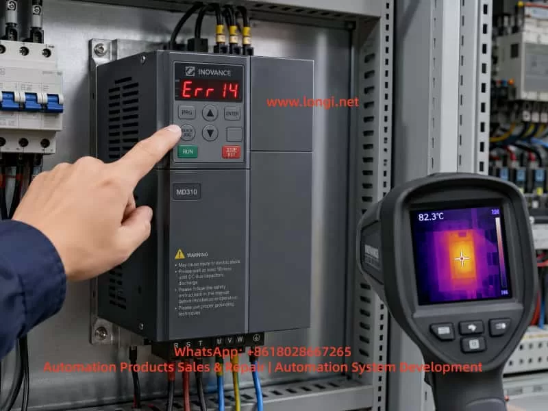
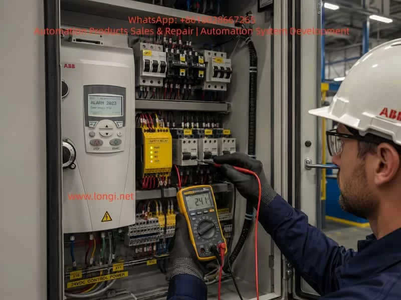
During long-term operation, VFD fault codes are one of the most important clues for diagnosing equipment problems. When an Inovance MD310 VFD displays Err14, it generally indicates module overheating. In practical maintenance work, this usually refers to overheating of the power module, IGBT module temperature protection, or an abnormal module temperature detection signal.
At first glance, Err14 may appear to be a simple high-temperature alarm. However, the actual cause can be more complex. In some cases, the power module is genuinely overheating because of poor ventilation, a failed cooling fan, blocked heatsink fins, high cabinet temperature, or excessive load current. In other cases, the VFD may display Err14 immediately after power-on, even before the motor runs. In this situation, the heatsink is still cold, so the fault is unlikely to be caused by real overheating. Instead, the likely cause may be a faulty temperature sensor, abnormal temperature detection circuit, damaged driver board, poor connector contact, or IGBT module temperature feedback failure.
Therefore, troubleshooting Err14 should not stop at the simple conclusion that “the VFD is too hot.” A correct diagnosis must combine the fault timing, load condition, ambient temperature, running current, ventilation system, parameter settings, and internal circuit condition. This article provides a systematic technical analysis of the Err14 fault on the Inovance MD310 VFD, including its meaning, common causes, field troubleshooting steps, repair logic, and preventive maintenance recommendations.
2. Basic Meaning of Err14 on the MD310 VFD
On the Inovance MD310 series, Err14 normally means module overheating. The “module” mainly refers to the internal power inverter section, including the IGBT power module, freewheeling diodes, driver circuit, heatsink, and temperature detection components.
When a VFD operates, the input AC power is first rectified into DC bus voltage. The IGBT inverter section then converts the DC bus into a variable-frequency, variable-voltage three-phase AC output for the motor. During high-speed switching, IGBTs generate switching losses and conduction losses. These losses become heat. If the heatsink, cooling fan, and airflow path cannot remove this heat efficiently, the module temperature will rise. When the temperature reaches the protection threshold, the VFD will stop output and display a fault code to prevent further damage to the power devices.
However, Err14 does not always mean that the IGBT has failed, and it does not always mean that the heatsink is actually hot. In essence, the control system has detected an abnormal module temperature signal. This signal may come from real high temperature, or it may come from an abnormal detection circuit.
Therefore, during maintenance, Err14 should be divided into two major categories.
The first category is real overheating. The VFD runs for a period of time before the alarm appears. The heatsink is hot, the fan may be stopped or weak, the airflow path may be blocked, or the output current may be too high. In this case, the main focus should be cooling, ventilation, and load condition.
The second category is false overheating. The VFD reports Err14 immediately after power-on, before the motor starts. The heatsink is cold, and the machine has not produced any meaningful heat. In this case, the fault is more likely related to the temperature sensor, temperature sampling circuit, driver board, control board, connector, or internal module feedback signal.
This distinction is very important. Real overheating requires thermal and load correction. False overheating requires electrical diagnosis and board-level repair.
3. Main Components Related to Err14
To analyze Err14 correctly, it is necessary to understand which internal parts of the VFD are related to module temperature protection.
3.1 IGBT Power Module
The IGBT power module is the core component responsible for generating the three-phase output voltage. It withstands the DC bus voltage and switches rapidly under PWM control. During operation, the IGBT produces heat. The amount of heat depends on output current, carrier frequency, load characteristics, cooling performance, and switching condition.
If the motor is overloaded, mechanically jammed, frequently started and stopped, or if the acceleration and deceleration time is too short, the IGBT thermal stress will increase. A high carrier frequency also increases switching loss and can raise module temperature.
3.2 Heatsink
The power module is usually mounted on an aluminum heatsink. Heat is transferred from the module to the heatsink through thermal grease or a thermal interface material, and then removed by air. If the heatsink fins are blocked by dust, oil, cotton fibers, wood dust, or metal particles, heat dissipation becomes poor. Even if the fan is running, the thermal performance may still be insufficient.
3.3 Cooling Fan
Many compact VFDs rely on built-in cooling fans for forced-air cooling. A cooling fan may fail completely, rotate slowly, make abnormal noise, or become unstable after running for several minutes. Fan bearing wear is very common in old drives. A weak fan may still appear to be rotating, but the actual airflow may be insufficient. This is why checking fan speed and airflow is more important than simply checking whether the fan moves.
3.4 Temperature Detection Element
The VFD normally monitors power module temperature through a thermistor, temperature sensor, or internal temperature feedback pin of the module. The control board receives this signal and determines whether the module is overheated.
If the thermistor is open-circuit, short-circuit, drifting in resistance, or if the sampling circuit is damaged, the control board may mistakenly judge that the module temperature is too high. This can cause Err14 even when the module is cold.
3.5 Driver Board and Control Board
The temperature signal is often processed by the driver board or control board before being sent to the CPU. If the driver board power supply is abnormal, the sampling resistor has changed value, the connector is oxidized, the ribbon cable has poor contact, or the CPU input circuit is damaged, Err14 may be triggered incorrectly.
For repair engineers, if the heatsink is cold but the drive still reports Err14, the temperature detection path should be checked carefully.
4. Common Causes of Err14
4.1 Cooling Fan Failure or Low Fan Speed
This is one of the most common causes. During operation, the IGBT and rectifier section continuously generate heat. If the cooling fan does not work properly, the heatsink temperature will gradually rise and eventually trigger Err14.
The field inspection method is straightforward. Observe whether the fan rotates, listen for abnormal noise, and feel whether there is enough airflow from the outlet. It is important not to judge the fan only by whether it rotates. Some old fans rotate slowly, start with difficulty, or stop after running for a short time. These faults are easy to miss.
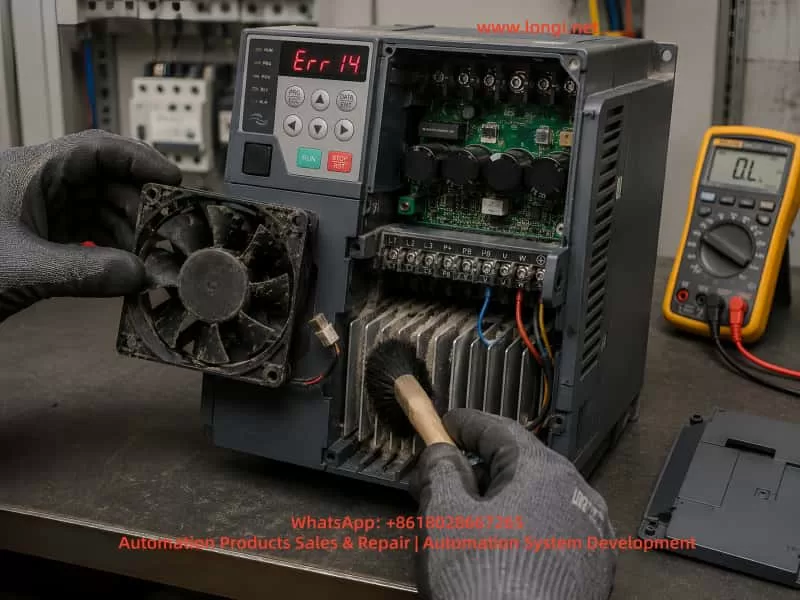
For old VFDs operating in dusty environments, replacing the fan directly is often more reliable than only cleaning it.
4.2 Blocked Airflow Path or Dusty Heatsink
Many VFDs are installed in environments with dust, oil mist, fibers, wood powder, or industrial particles. Over time, the heatsink fins become blocked. Even if the fan is working, air cannot pass through the heatsink effectively.
This type of problem usually has a clear pattern: the VFD works normally at first, then reports Err14 after running for some time. After cooling down, it can restart again. Once the heatsink and airflow path are cleaned thoroughly, the fault may disappear.
During maintenance, the cover should be removed after the DC bus is safely discharged. The heatsink fins, inlet, outlet, and internal air duct must be cleaned properly. Cleaning only the surface is not enough.
4.3 High Control Cabinet Temperature
Sometimes the VFD itself is normal, but the control cabinet temperature is too high. This is especially common in summer, high-temperature workshops, sealed cabinets, or cabinets containing several drives, contactors, power supplies, servo drives, and braking resistors.
The technician should measure the temperature inside the cabinet and check whether the cabinet has a proper air inlet, exhaust fan, filter, or air conditioner. Some cabinets only use internal circulating fans. This does not remove heat from the cabinet and therefore has limited effect. Real cooling requires cold air intake and hot air exhaust.
4.4 Insufficient Installation Clearance
A VFD needs enough space around it for heat dissipation. If several drives are installed too close to each other, or if wiring ducts and panels block the top outlet, hot air cannot escape smoothly.
Compact drives are often installed in tight spaces because they are small. However, poor installation clearance can directly cause overheating. This is especially common in retrofit projects where the cabinet space is limited.
4.5 Heavy Load or Motor Abnormality
Although Err14 is a module overheating fault, the root cause may be excessive output current. A jammed bearing, heavy mechanical load, dry gearbox, tight belt, blocked fan impeller, blocked pump, or high conveyor resistance can all increase motor current.
Higher current means higher IGBT loss and higher module temperature. In this case, repairing only the VFD is not enough. The motor and mechanical load must also be inspected.
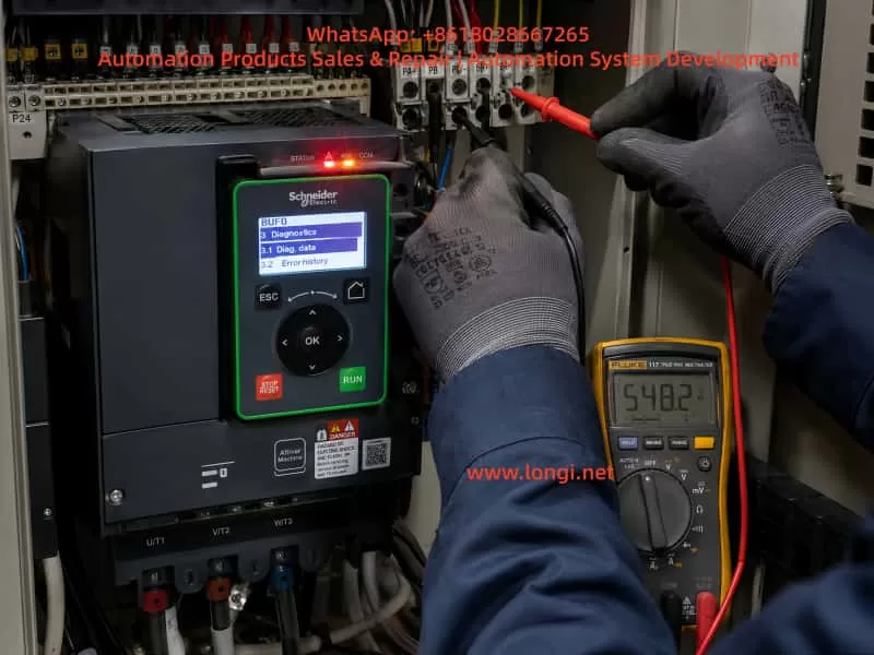
A practical method is to check the VFD output current during operation and compare it with the motor rated current. A clamp meter can be used to verify whether the three-phase output current is balanced. If the drive runs normally without load but reports Err14 under load, the mechanical system should be inspected first.
4.6 Carrier Frequency Set Too High
A higher carrier frequency can reduce motor electromagnetic noise and improve current waveform quality, but it increases IGBT switching loss. Under heavy load or high ambient temperature, excessive carrier frequency may cause module overheating.
In this situation, the carrier frequency parameter should be reduced appropriately. After lowering the carrier frequency, the motor may produce more audible noise, which is normal. For fans, pumps, and general conveyor applications, an unnecessarily high carrier frequency is usually not required.
4.7 Acceleration or Deceleration Time Too Short
If the equipment starts, stops, reverses, or changes speed frequently, or if the acceleration time is set too short, the VFD may output high current for a short period. This increases IGBT thermal stress.
Large-inertia loads such as centrifugal fans, centrifuges, heavy conveyors, and winding systems are especially sensitive to short acceleration and deceleration settings. In these cases, Err14 may appear together with overcurrent, overload, overvoltage, or braking-related faults.
The acceleration and deceleration time should be adjusted according to the load inertia. If necessary, braking resistors or optimized stopping methods should be considered.
4.8 Temperature Detection Circuit Failure
If the VFD displays Err14 immediately after power-on and the heatsink is cold, real overheating is unlikely. The temperature detection circuit should then be investigated.
Common problems include open or shorted thermistor, abnormal thermistor resistance, damaged module temperature feedback pin, changed-value sampling resistor, poor connector contact, abnormal driver board circuit, or damaged control board input channel.
Board-level diagnosis usually requires measuring the temperature detection signal voltage or resistance and comparing it with a normal unit. Without a reference unit, the technician must analyze the thermistor characteristics carefully. The temperature protection circuit should not be simply shorted or bypassed for long-term operation, because it is an important protection function.
4.9 IGBT Module Aging or Damage
If the IGBT module itself has internal damage, poor thermal contact, or abnormal temperature feedback, Err14 may also appear. If the VFD also has output phase loss, unbalanced current, unusually fast temperature rise, or abnormal output waveform, the power module should be checked.
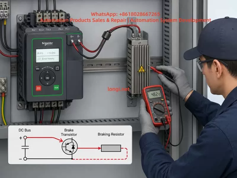
After power-off and safe discharge, a multimeter diode test can be used to check the diode characteristics between P, N, and U/V/W terminals. The readings should be relatively balanced among the three output phases. Any short circuit, open circuit, or obvious phase-to-phase inconsistency indicates that the power module may be defective.
5. Recommended Field Troubleshooting Procedure
For efficient field diagnosis, the troubleshooting process should follow a clear order: external first, internal later; cooling first, circuit later; operating condition first, board-level repair later.
Step 1: Confirm When the Fault Appears
The first question is: when does Err14 appear?
If Err14 appears immediately after power-on before running, suspect temperature detection or board failure.
If Err14 appears after several minutes or tens of minutes of operation, suspect cooling, ventilation, high load, or high ambient temperature.
If the fault appears only at high speed but not at low speed, check carrier frequency, output current, cooling condition, and motor load.
If the fault appears mainly in summer but not in winter, inspect cabinet cooling and ambient temperature.
If the fault started after changing the motor or mechanical system, check motor parameters, load matching, and running current.
Step 2: Check the Cooling Fan
Observe the fan operation, fan speed, and noise. Feel the airflow at the outlet. If the fan starts slowly, stops intermittently, has weak airflow, or makes abnormal noise, replace it. The fan is a low-cost part, but it has a major influence on VFD reliability.
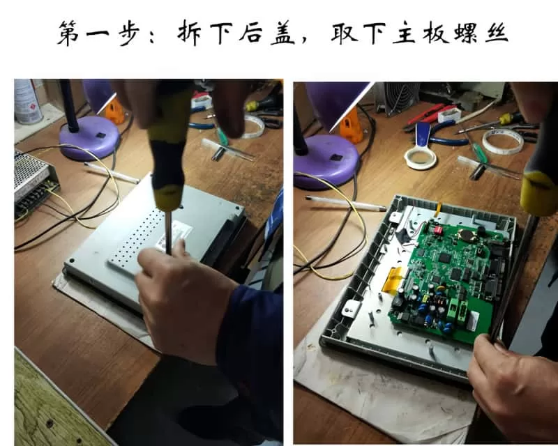
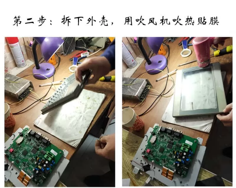
Step 3: Clean the Heatsink and Air Duct
After disconnecting power and confirming DC bus discharge, remove the cover and inspect the heatsink, inlet, outlet, and internal air path. Clean dust and oil contamination thoroughly. In harsh environments, surface cleaning is not enough; the heatsink fins must be cleared.
Step 4: Check the Installation Environment
Check whether the VFD has enough space above and below it, whether the cabinet is sealed, and whether hot air can escape. If several VFDs are installed close together, thermal accumulation must be considered. If the cabinet temperature is high, add ventilation, exhaust fans, or an industrial air conditioner.
Step 5: Check Running Current
Run the equipment under normal load and observe the VFD output current. Use a clamp meter to verify the current if necessary. If the current is close to or above the rated current for a long time, inspect the motor and mechanical load. For pumps and fans, check the pipeline, valve position, impeller, bearing, and mechanical resistance.
Step 6: Check Parameter Settings
Important parameters include motor rated voltage, rated current, rated frequency, rated speed, control mode, acceleration time, deceleration time, and carrier frequency. Incorrect motor parameters may cause high current. A high carrier frequency increases module heating. Too short acceleration and deceleration time increases thermal shock.
Step 7: Determine Whether It Is False Overheating
If the cooling system, environment, load, and parameters are all normal, and the VFD reports Err14 while cold, the issue should be treated as false overheating. The temperature detection circuit, connectors, ribbon cables, driver board, control board, and module feedback circuit should then be checked.
The technician should not permanently bypass the temperature protection circuit simply to make the drive run. Doing so can cause severe IGBT damage and higher repair cost.
6. Safety Precautions During Repair
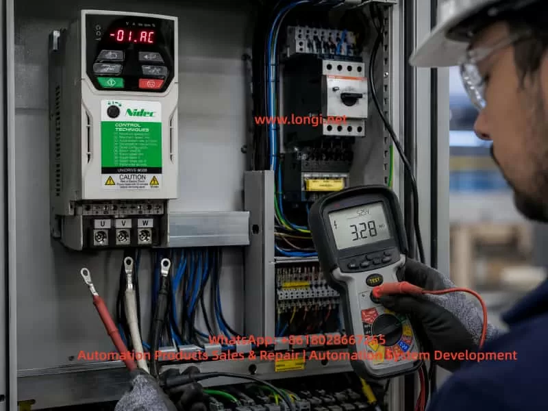
A VFD contains a high-voltage DC bus. Even after power is disconnected, the capacitors may still hold several hundred volts. Before opening the drive, wait long enough and measure the voltage between P and N terminals to confirm that it has dropped to a safe level. Do not assume that the drive is safe just because the keypad display is off.
When cleaning the inside of the VFD, prevent screws, wire ends, or metal particles from falling onto the PCB. When using compressed air, avoid excessive pressure because it may damage small components or push dust deeper into the drive. If cleaning solvent is used, it must be suitable for electronic equipment and must fully evaporate before power-on.
When testing the IGBT module, avoid live measurement at the U, V, and W output terminals during operation. The output waveform is high-frequency PWM, and ordinary multimeter readings may not be meaningful. Incorrect measurement may damage the instrument or create a safety hazard.
When replacing the cooling fan, confirm the voltage, size, airflow direction, connector type, and installation direction. If the fan is installed backwards, cooling performance will be reduced, and hot air may circulate inside the drive.
7. Relationship Between Err14 and Other Faults
Err14 may not always appear alone. It can occur together with overcurrent, overload, undervoltage, overvoltage, or braking-related faults. For example, if the mechanical load is jammed, the VFD may first experience high output current, then the power module heats rapidly, and finally Err14 appears. Poor cooling may also cause the power devices to operate at high temperature, resulting in unstable switching characteristics and additional faults.
Therefore, when a site reports that the drive sometimes shows Err14 and sometimes shows overcurrent, these should not be treated as completely separate problems. The technician should look for common causes such as excessive load, poor cooling, aging power module, abnormal driver waveform, motor insulation problem, or incorrect parameter settings.
8. Typical Case Analysis
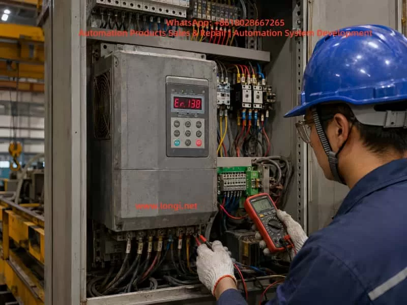
In one field case, an Inovance MD310T2.2B series VFD was used to drive a small motor. After running for a period of time, the drive stopped and displayed Err14. At first, the site suspected that the VFD was damaged. After inspection, however, the control cabinet was found to be dusty, the heatsink fins were blocked, and the built-in fan speed was weak. After cleaning the heatsink and replacing the fan, the drive resumed normal operation and the fault did not return.
In another case, the VFD displayed Err14 immediately after power-on. The motor had not started, and the heatsink was completely cold. Replacing the fan and cleaning the airflow path did not solve the issue. After board-level inspection, the temperature detection circuit was found to be abnormal, causing the control board to continuously receive an over-temperature signal. This case shows that Err14 is not always caused by real overheating. If the alarm appears while the drive is cold, the temperature feedback circuit should be checked first.
9. Preventive Maintenance Recommendations
To reduce the possibility of Err14 faults on MD310 VFDs, regular maintenance is necessary.
First, clean the control cabinet and VFD air duct regularly. In dusty environments, inspection every one to three months is recommended. In normal environments, inspection every six months may be sufficient.
Second, check the cooling fan regularly. The fan is a wear part. After long-term operation, bearing wear, low speed, and startup failure are normal aging symptoms. For equipment running continuously, preventive fan replacement is recommended.
Third, ensure proper cabinet ventilation. The cabinet should have a clear intake and exhaust path. Filters should be cleaned regularly. If the cabinet temperature remains high, an additional fan or industrial air conditioner should be installed.
Fourth, set carrier frequency and acceleration/deceleration time reasonably. Do not increase carrier frequency only to reduce motor noise, and do not set acceleration time too short only to achieve faster machine movement.
Fifth, pay attention to the motor and mechanical load. Many overheating faults are not caused by the VFD itself but by excessive output current due to mechanical problems. Electrical maintenance and mechanical inspection should be combined.
Sixth, do not repeatedly reset and restart the drive after Err14 appears. If real overheating has not been eliminated, repeated reset operation may eventually damage the IGBT module and increase repair cost.
10. Conclusion
When an Inovance MD310 VFD displays Err14, the core meaning is module overheating or abnormal module temperature detection. The correct repair approach is to first distinguish between real overheating and false overheating.
If Err14 appears after the drive has been running for some time, the most likely causes are fan failure, blocked airflow, high ambient temperature, excessive load current, improper installation clearance, high carrier frequency, or unreasonable acceleration and deceleration settings.
If Err14 appears immediately after power-on while the drive is still cold, the fault is more likely related to the temperature detection circuit, driver board, control board, connector, or power module temperature feedback signal.
The correct troubleshooting method is not simply resetting the fault or declaring the VFD damaged. Instead, the technician should analyze the fault timing, cooling system, load condition, parameter settings, and internal detection circuit step by step.
For field maintenance engineers, Err14 is a typical comprehensive VFD fault. It can be caused by environment and maintenance problems, but it can also be caused by circuit board or power module faults. Only by combining external inspection with internal electrical diagnosis can the fault be located accurately and unnecessary replacement avoided.
In daily use, good ventilation, regular air duct cleaning, timely fan replacement, reasonable parameter settings, and proper load inspection are the key measures to prevent Err14 on the Inovance MD310 series. For drives that report Err14 immediately after power-on, professional inspection should be carried out as soon as possible, with special attention to the temperature detection circuit and power module feedback signal.