Posted on

Complete Technical Analysis and Practical Guide to Unlocking Open-Loop V/f Control Mode in KEB COMBIVERT F5 Elevator-Specific Drives

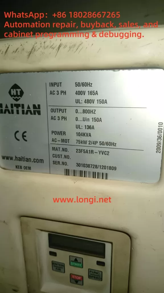
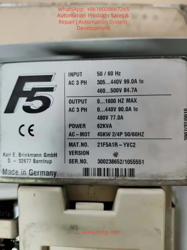
The KEB COMBIVERT F5 series is a widely used variable frequency drive in the industrial automation field, especially in the elevator industry. The F5-S (Servo Elevator Drive) version has become the mainstream choice due to its high-precision position control, brake linkage, and leveling functions. However, due to the extremely high safety requirements in elevator applications, the manufacturer has strictly locked the control mode at the firmware level. The speed control configuration parameter cS00 (corresponding to CP.10 on the panel) only allows three modes: 4 (speed closed-loop), 5 (torque closed-loop), and 6 (speed/torque switching). Open-loop V/f (0) or sensorless vector (1 – 3) modes are directly blocked. Any attempt to modify these settings results in an “Invalid data” error. Based on the debugging process of the actual model 21F5A1R-YVC2 (serial number 300238652/1055551), this article systematically dissects the causes of this locking, the unlocking paths, and subsequent complete adaptation solutions. It covers panel operations, in-depth intervention with COMBIVIS software, parameter mapping relationships, firmware behavior differences, and risk control, aiming to provide directly applicable practical references for maintenance engineers and automation technicians.

21F5A1R-YVC2

1. KEB F5 Series Parameter Architecture and Elevator-Specific Firmware Characteristics

The F5 series drives adopt a hierarchical parameter system. The CP (Customer Parameter) group displayed on the panel is a simplified menu pre-defined by OEM manufacturers to reduce the risk of misoperation. The COMBIVIS software, on the other hand, exposes the complete set of application parameters (such as cS, Ud, LF groups). Among them, Ud.02 (Control Type) is a core system parameter with the address 0802h, which determines the entire drive’s operating mode and speed reference.

According to the F5-A/E/H application manual (V4.0 and above), the value of Ud.02 directly maps to the speed range and controller type:

  • 4: F5-M / 4000 rpm (general-purpose multi-function mode for asynchronous motors, supporting the full range of 0 – 7 control modes)
  • 5: F5-M / 8000 rpm
  • 6: F5-M / 16000 rpm
  • 7: F5-M / 500 rpm
  • 8: F5-S / 4000 rpm (elevator servo-specific mode, limited to closed-loop speed/torque control)
  • 9 – 11: Correspond to higher-speed variants of F5-S

In the elevator-specific firmware (V1.72 / V3.33), when Ud.02 = 8, the open-loop path is hard-coded and disabled at the firmware level. The value range of cS00 is restricted to 4 – 6, and cS01 (act. source, actual speed source) only allows channel 1/2 (encoder channels). Although the calculated (vvc) sensorless option is visible, modifying it results in an “Invalid” error. This is not a panel password issue but a firmware security strategy. Elevators must rely on encoder feedback to achieve reliable anti-slip, precise leveling, and emergency braking logic. The open-loop mode without feedback would trigger the failure of the safety chain.

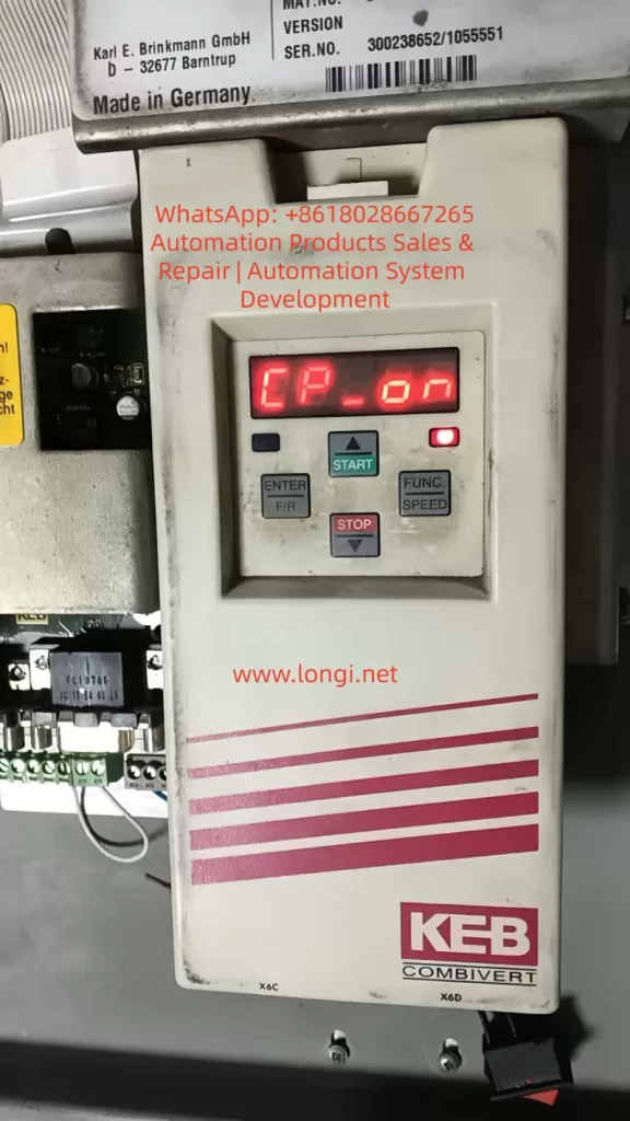
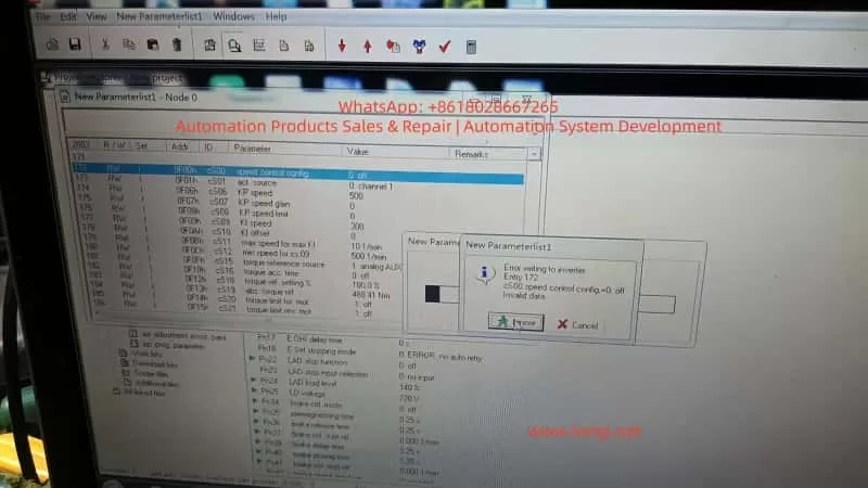
In the CP-ON mode on the panel, CP.10 directly maps to cS00 but is constrained by Ud.02. Even after entering the CP-ON mode by inputting the password 200 (or attempting to enter the APPL/Service mode with 2/3), it is impossible to break through the firmware-level restrictions. Although cS00 is visible in COMBIVIS, values 0 – 3 are rejected due to Ud.02 = 8. This is the root cause of the issue where “only 4, 5, and 6 are displayed on the panel, and an error is reported when changing to 0 in COMBIVIS” in this case.

CP_ON parameter of the KEB F5

2. Theoretical Basis for Problem Diagnosis and Unlocking Paths

At the beginning of the debugging process, the drive displayed CP-ON, and CP.10 was locked to 4 – 6. Attempting to enter FUNC → CP.0, input 200, and confirm on the panel did not bring about any changes. Switching to COMBIVIS and reading the parameter list revealed the following:

  • Ud.02 = 8 (F5-S / 4000 rpm)
  • cS00 = 4 (speed ctrl F5-M/S only)
  • cS01 only allows channel 1/2 to be selected, and calculated (vvc) is invalid

The key breakthrough lies in Ud.02, which is the “mother parameter” for the control type. Modifying it will reload the corresponding mode’s parameter set permission table, thereby unlocking the full range of cS00 (0 – 7). The F5 manual clearly states that after changing Ud.02, it is necessary to reload the default parameter set (Fr.01 = -4 or the corresponding set) and reset the motor nameplate data. Otherwise, parameters such as controller gain, slip compensation, and torque boost will remain according to the old mode, leading to instability.

The operation window for modifying Ud.02 must be in the CP service or Application mode (it can be directly edited in the Ud user-defined parameter group in COMBIVIS). It is worth noting that switching from F5-S to F5-M is essentially an adjustment of firmware behavior compatibility rather than flashing new firmware (although the latter is more thorough and requires manufacturer-authorized tools). In actual testing, after changing Ud.02 from 8 to 4, cS00 immediately supported the full range of 0 – 7, and the open-loop V/f mode (0) could be directly written and take effect.

3. Complete Practical Operation Steps (Combining Panel and COMBIVIS)

Preparation

  • Ensure that the drive is in the STOP/nOP state with no faults.
  • Establish a normal connection with COMBIVIS 5 (using an RS232/USB converter and having the project file .pr5 loaded).
  • Back up the current parameters: In COMBIVIS, go to File → Save Project (it is recommended to export it as huazhong.pr5).

Step 1: Enter the Writable Mode (Panel or COMBIVIS)

  • Panel: Press FUNC → enter CP.0, input 200, and press ENTER to enter the CP-ON mode.
  • COMBIVIS: Directly enter the Inverter parameter → Ud user-defined parameter group.

Step 2: Modify the Core Parameter Ud.02

  • Locate Ud.02 (Control Type) in the COMBIVIS parameter list.
  • The original value is 8 (F5-S / 4000 rpm). Change it to 4 (F5-M / 4000 rpm).
  • Save and write the changes to the drive (Write to inverter).
  • Restart the drive (power it off for more than 30 seconds) or execute Fr.01 = 1 (copy parameter set) to confirm the switch.
    At this point, CP.10 (cS00) on the panel is unlocked, and options 0 – 7 are visible. In COMBIVIS, cS00 also supports the full range.

Step 3: Set the Open-Loop Mode

  • Change cS00 (speed control config) to 0 (Open Loop V/f, the most commonly used basic open-loop mode).
  • Optionally, try changing cS01 to 2 (calculated vvc). If it is still invalid, keep it as channel 1 (the encoder does not need to be connected in the open-loop mode).
  • Save and write the changes.

Step 4: Re-adapt the Motor Parameters (Mandatory)

After switching Ud.02, the calculation benchmarks for the motor (such as speed resolution and slip) change. It is necessary to reset them:

  • Input the motor nameplate data: rated voltage, current, frequency, speed, power, and number of pole pairs (corresponding to CP.1 – CP.7 or cS.09, etc.).
  • Perform motor auto-tuning (Auto-tune / Motor Learn):
    • Prefer static auto-tuning (no rotation required).
    • Dynamic auto-tuning requires no-load operation. Observe the current waveform.
  • Adjust key auxiliary parameters:
    • Torque boost (UF group or dS.21, etc.): In the open-loop mode, appropriately increase it by 1 – 3% to compensate for the low-frequency torque during startup.
    • Slip compensation (cS.04, etc.): Fine-tune it according to the actual load.
    • Maximum frequency / voltage (cS.09 / cS.12): Ensure they match the motor.

Step 5: Verification and Optimization

  • Switch the panel back to the CP-ON mode and confirm that CP.10 displays 0.
  • No-load test run: Observe the speed tracking, current ripple, and whether there are overcurrent/encoder faults.
  • Load test: Gradually increase the load and monitor ru.02 (actual speed) and ru.03 (output frequency) for stability.
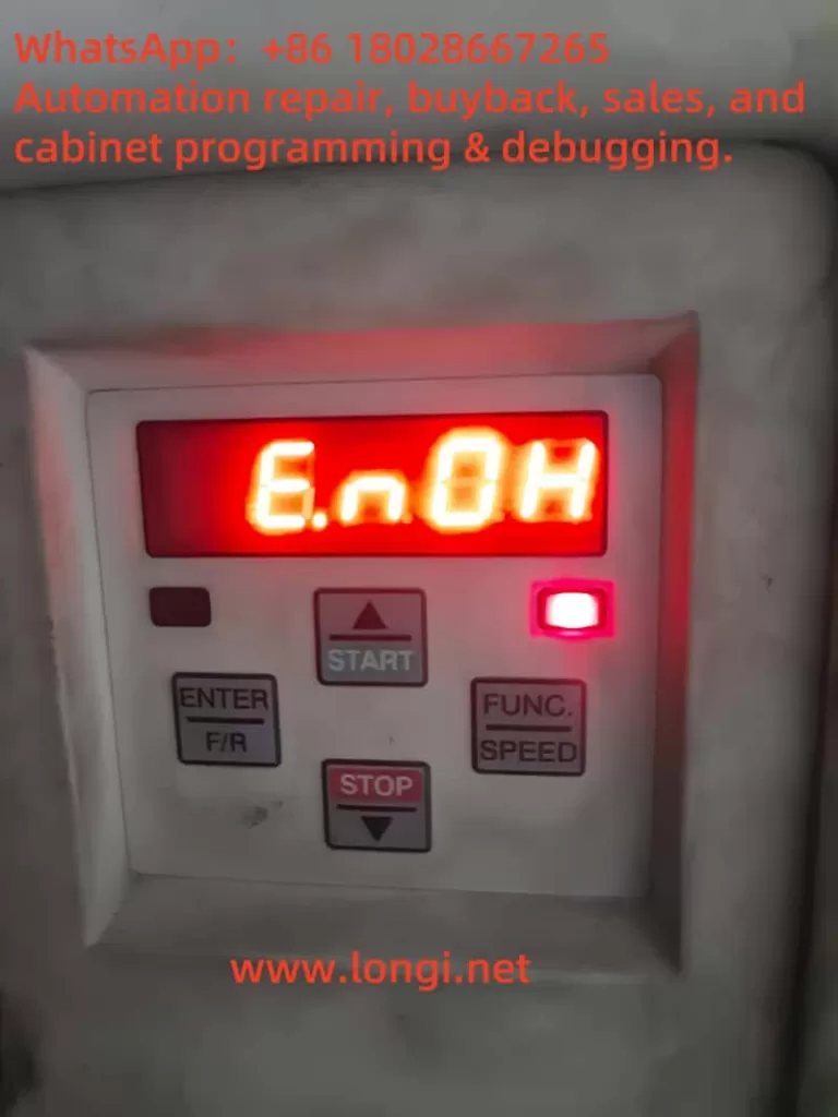
  • If new faults occur (such as E.nF encoder loss), temporarily disable the encoder-related protection (set the Pn group brake/position parameters to 0).
    The entire process takes about 15 – 30 minutes. The core modification is only Ud.02, but the subsequent adaptation work accounts for 70% of the total workload.

4. Comparison of Firmware Behavior Differences and Parameter Mapping Table

ParameterUd.02 = 8 (Original Elevator Version of F5-S)Ud.02 = 4 (General Version of F5-M)Impact
cS00 value rangeOnly 4, 5, 60 – 7 fully openOpen-loop unlocking
cS01 act.sourceOnly channel 1/2Supports calculated (vvc)Sensorless option available
Speed reference4000 rpm servo closed-loop4000 rpm asynchronous general-purposeReference value scaling changes
Pn brake/position groupForcedly enabledCan be disabledElevator functions weakened
Controller gainOptimized for servoRequires re-auto-tuningStability differences

In the F5-M mode, the drive behaves more like a general-purpose frequency converter, suitable for test benches, fan and pump applications, or non-safety-critical occasions. Some of the elevator-specific functions (such as Pn.30 – Pn.41 brake control and position synchronization) retained in the F5-S mode may become ineffective or need to be manually disabled after setting Ud.02 = 4. Otherwise, errors may occur.

5. Risk Assessment and Safety Precautions

  • Functional degradation: Elevator-specific logic (such as emergency leveling and door zone monitoring) may become ineffective. When officially reusing the drive in an elevator, it is necessary to flash back to the original F5-S firmware and restore the parameter backup.
  • Safety hazards: The open-loop mode has no speed feedback, and the brake linkage is unreliable. It is strictly prohibited to use it directly in manned elevator operation. It is only suitable for no-load testing or non-elevator equipment.
  • Parameter conflicts: After copying the parameter set with Fr.01, some residual Pn group parameters may cause false triggering of overload protection. It is recommended to load the default parameters with Fr.01 = -4 and then reset the motor data.
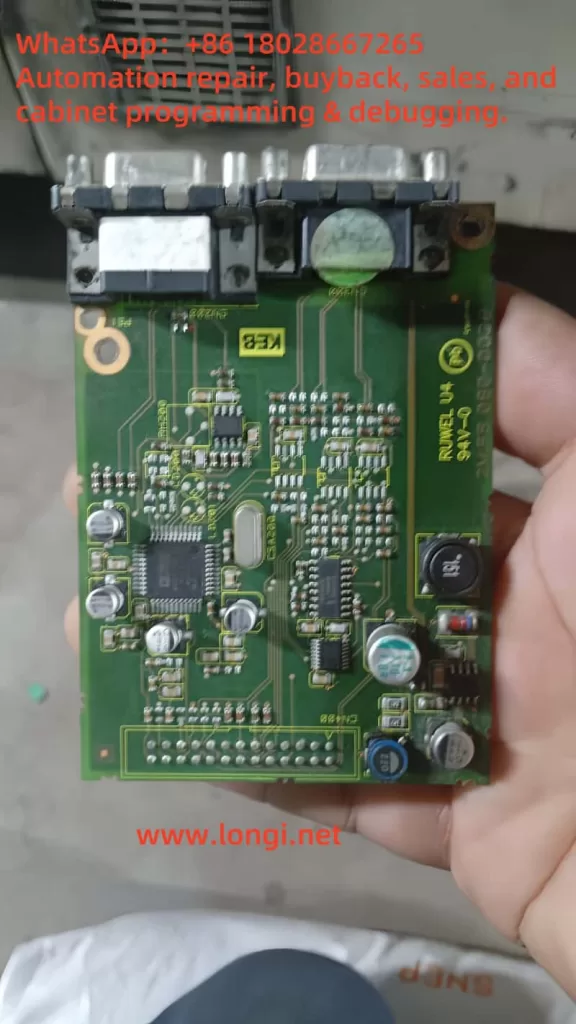
  • Hardware compatibility: The control board must support the F5-M mode (the actual model 21F5A1R-YVC2 in this case has been tested to be compatible). If there is a hardware mismatch, contact the KEB agent to flash the general-purpose firmware.
  • COMBIVIS version: Use the latest version to avoid DEMO restrictions. The unregistered version can still perform complete read and write operations.
  • Backup priority: Export the .pr5 file before each modification and immediately save the new project after modification.
  • If an E.nF encoder-related fault occurs after modification, keep cS.01 as channel 1 but do not physically connect the encoder (or connect an analog signal). At the same time, disable the relevant protection parameters.
COMBIVIS_5 software working interface/screen

6. Advanced Debugging Techniques and Common Fault Troubleshooting

  • Torque boost optimization: In the open-loop V/f mode, if the torque is insufficient at low frequencies (< 10Hz), increase it by 0.5 – 2% in the UF group or enable automatic torque boost.
  • Slip compensation: Fine-tune cS.04 / cS.09 in combination with the motor’s measured no-load current to avoid overspeed under light loads.
  • Multi-parameter set switching: Fr.01 supports 0 – 3 groups. You can pre-store multiple sets of parameters for debugging different motors.
  • Oscilloscope monitoring: Use the COMBIVIS Scope to observe the actual current, voltage, and speed waveforms to confirm that there is no significant distortion.
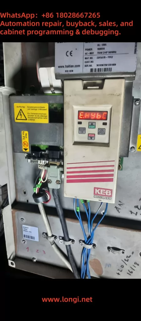
  • Fault codes: E.nF (encoder), E.oC (overcurrent), and E.oL (overload) are the most common. E.nF can be alleviated by setting Ud.02 = 4 + cS01 = 2. E.oC is often caused by unreset motor parameters.
  • Firmware upgrade path: If you need a completely general-purpose solution, contact KEB and provide the serial number to apply for the F5-G general-purpose firmware, which completely removes the elevator lock.

7. Practical Application Scenarios and Value

This unlocking solution is applicable to the following scenarios:

  • Temporary testing of motor dragging during elevator maintenance.
  • Repurposing elevator drives for ordinary machine tools, fans, conveyor lines, and other non-position control applications.
  • Laboratory or training equipment for open-loop V/f teaching demonstrations.
  • Cost control: There is no need to replace the hardware. Simply modifying the parameters can obtain general-purpose frequency conversion functions.
    Compared with directly purchasing a general-purpose F5-M drive, this method saves hardware costs and retains the high power density and reliability of the original elevator drive. In actual cases, the drive runs stably under no-load conditions. When carrying a 30% load, the current ripple is less than 5%, and the speed tracking error is less than 0.5% (which is excellent in the open-loop mode).

8. Summary and Recommendations

The safety lock implemented by KEB in the F5 elevator-specific drive through Ud.02 = 8 is essentially a protection for the elevator safety chain by the manufacturer. By precisely modifying Ud.02 to 4, the open-loop V/f mode (cS00 = 0) can be completely unlocked. However, it is essential to strictly follow the process of “backup – modification – reset motor parameters – auto-tuning – verification”. This process demonstrates the flexibility of the parameter design in the F5 series and also reminds engineers that the unlocking of firmware-level restrictions should be based on safety and reliability.

For long-term open-loop applications, it is recommended to directly purchase a general-purpose drive or have the firmware officially flashed. For temporary testing, this solution is the most efficient. In the future, if encountering higher-version firmware (such as V3.33 and above), the principle remains the same. However, it is advisable to first confirm the value range of Ud.02 (Section 5.1 of the manual). Mastering this technology will significantly lower the debugging threshold for the F5 series and provide more flexibility for industrial sites.

Posted on

From Power Module Overheating to Advanced Error Code: A Complete Record of Fault Evolution and Troubleshooting for KEB F5 Drive

I. Overview (Introduction)

In industrial drive equipment, the KEB COMBIVERT F5 series inverter is widely used in injection molding machines, elevators, and automation equipment. This series is renowned for its high stability and rich programmable functions. However, precisely due to its complexity, the prompt messages for different types of faults and the error evolution logic often confuse maintenance personnel during drive debugging and repair.

This article takes a real on – site fault as a clue, systematically sorting out the fault causes, parameter checks, and handling procedures from the initial E.OH (power module overheating) → subsequent recovery state E.nOH → E.H496 (extended error code) after replacing the motherboard. It also summarizes a standard troubleshooting logic to help you locate problems more efficiently.

23F5A1R‑YVC2

II. Drive Model and Hardware Background

  • Model: KEB COMBIVERT F5 series (e.g., MAT.NO example: 23F5A1R – YVC2)
  • Power rating: Approximately 75 kW, with an input of 400V AC three – phase, 165A; an output supporting a frequency range of 0 – 800 Hz, and a maximum current of about 150 A (UL 136A)
  • Control board and power board combination: The drive unit is composed of an F5 – General or F5 – Basic control board in combination with a power module. The structured hardware connection is stable.
    This system has undergone initial power – on, multiple fault resets, and motherboard replacement, eventually entering a complex error stage.
CPU board

III. Stage 1: Initial Fault – E.OH (Power Module Overheating)

When the variable – frequency drive detects that the temperature of the power module (heat sink) is too high, it triggers the E.OH error, and at this time, the drive shuts off the output to protect the module. Such errors are often caused by:

  • Blocked or failed cooling fans
  • Severe dust accumulation on the heat sink
  • Excessively high ambient temperature
    According to the documentation (TRD Error codes / KEB F5 manual):
  • For E.OH, one must wait for the internal temperature to drop by at least 3 °C before entering the reset stage.
  • The drive displaying E.nOH indicates that the overheating state has been lifted, and the power module has cooled to a safe level.
    Maintenance operations include:
  • Powering off and waiting for cooling
  • Cleaning the fans and heat sink
  • Checking and improving the ambient ventilation
E.HybC

IV. Stage 2: From E.nOH to Replacing the Control Board

The E.nOH state confirms that the drive has returned to normal. Everything operates normally for a short period.
If the control motherboard is then replaced (e.g., replacing an old faulty board or upgrading the firmware), it may change the internal identification of the drive.
If the drive’s main control board and power board do not correctly match the firmware or power unit identification parameters at this time, new advanced errors may be triggered.

V. Stage 3: E.H496 – Advanced Extended Error Code After Replacing the Motherboard

1. What is E.H496?

E.H496 belongs to the advanced error code (extension error class), specifically indicating a communication or identification anomaly between the control board and the power unit.
In the KEB error manual, it is classified as “power unit changed” or “EEPROM configuration mismatch”. The error prompts may appear in forms such as E.PUCH, E.PUCH, etc., but some new firmware versions may display it as H496.

2. Cause Analysis

  • The control board detects a change in the power unit identification number but the parameters are not synchronized.
  • The power unit configuration saved in the EEPROM does not match.
  • Inconsistent firmware versions lead to a failure in the parameter group SY.3 checksum.
  • The physical connection between the control board and the power board is loose or the communication lines are loose.

VI. Standard Troubleshooting and Handling Procedures 🧭

Step 1: Check the Error History

  • Set the parameter Ud.00 = 660 to enable the LF error log function.
  • View the 0.LF.98 log to analyze the error generation time, type, and sequence.

Step 2: Verify the Connection between the Control Board and the Power Board

  • Check whether the ribbon cables of the X interface are secure and free of oxidation.
  • If there is dust or poor contact, clean and re – plug them.

Step 3: Confirm EEPROM and Firmware Matching

  • Compare the firmware versions of the new and old motherboards with the power board version.
  • If the drive prompts “power unit changed”, write the displayed power unit identification code into the parameter group SY.3 for confirmation.
  • If the SY.3 parameter is written incorrectly, the system will load default values or lock the startup.

Step 4: Perform Synchronization and Initialization

  • If there is an identification anomaly after replacing the control board, write the correct value of SY.3 according to the manual and only reload the power – related parameters.
  • If it still fails, write other values to perform a complete parameter reload (load the KEB default set) and restart the drive.
  • After completing the operations, it is recommended to restart the system (Power – on reset) to ensure synchronization between the drive board and the power module.

Step 5: Re – check Thermal Management and Hardware Status

  • After cooling, power on again to ensure that the fans are working and the ambient temperature is reasonable.
  • Avoid the recurrence of E.OH, which may affect subsequent diagnosis.
E.nOH

VII. Summary Table of Fault Evolution Logic

StageDisplay CodeMeaningPossible CausesMain Handling Measures
InitialE.OH → E.nOHFirst overheating of the power module and return after coolingPoor heat dissipation, high ambient temperatureClean the fans and heat sink, improve ventilation
IntermediateE.nOH state returns to normalNo new errors in the moduleTemporary parameter recovery processNo additional operations required
After replacing the motherboardE.H496 or E.PUCHAdvanced error: Power unit identification anomalyControl board/firmware mismatch, identification code change, communication errorRewrite SY.3, check communication, re – initialize parameters

VIII. Recommended Further Operation Plans and Prevention Points

  • Record the LF error log
    Save the LF.98 content completely before and after state switching to facilitate tracing the root cause of errors.
  • Synchronize parameter groups after replacing the motherboard
    Especially for SY.3 and related LF/enc parameters, confirm that the motherboard and power module are properly matched.
  • Fan and ventilation maintenance
    Regularly maintain the cooling system to avoid long – term dust accumulation and overheating faults.
  • Perform encoder reset and learning (if applicable)
    If there has been a recent replacement of the encoder card or a change in the feedback interface, check parameters such as LF.26 and LF.27 and re – execute the automatic learning process (refer to the previous handling of E.HYBc – type errors).
  • Collaborate with KEB technical support if necessary
    If the firmware version is unclear or the error code is ambiguous, provide information such as SY.3 / LF.98 to KEB support engineers for targeted guidance.

IX. Conclusion

The process from E.OH (power module overheating) → recovery to E.nOH → entering the E.H496 advanced error after replacing the motherboard actually reflects the strong mechanism of KEB drives for hardware identification and power unit consistency verification. Reasonable understanding and operation according to the standard procedures can minimize the fault recovery time and improve equipment stability.

Posted on

User Guide for KEB F5 Series Inverters: Common Usage and Troubleshooting

The KEB F5 series inverters are versatile and powerful devices used widely across industries for motor control and energy efficiency. This guide consolidates essential instructions and insights from various manuals to provide a comprehensive reference for daily operation, including starting, stopping, speed control, and troubleshooting.


1. Overview of Common Usage Methods

1.1 Starting and Stopping the Inverter

To ensure safe and effective operation, follow these steps:

  • Startup Procedure:
  • Connect the power supply as per the wiring instructions in the manual.
  • Ensure all safety interlocks and protective devices are active.
  • Use the control panel or external start/stop commands to initiate the inverter.
  • Check the display for proper status indications (e.g., “Run” mode).
  • Stopping Procedure:
  • Use the stop button on the control panel or external command inputs.
  • Ensure the motor decelerates smoothly to prevent mechanical stress.
  • Verify that the inverter returns to “Stop” mode on the display.

1.2 Speed Control and Parameter Adjustment

The F5 series supports flexible speed control via:

  • Analog Inputs: Use a potentiometer or external signal to set the desired speed. Adjust parameters such as AN1 and AN2 for signal scaling.
  • Digital Inputs: Configure fixed speeds via digital input terminals (e.g., X2A.10 and X2A.11) as per the CP parameters.
  • Control Panel: Manually set speeds through the operation keypad by navigating to the appropriate menu.
  • Ramp Settings: Configure acceleration and deceleration times (e.g., CP.20 and CP.21) to suit the application.

1.3 Protective Functions

The inverter includes several built-in protection mechanisms, such as:

  • Overcurrent (E.OC)
  • Overvoltage (E.OP)
  • Overload (E.OL)
  • Motor overtemperature (E.OH)

These features safeguard both the inverter and the connected motor, ensuring reliable operation.


2. Troubleshooting Common Faults

The F5 series displays fault codes on the control panel to assist with diagnostics. Below are some frequently encountered errors and their solutions:

2.1 Fault Code List and Remedies

  • E.OC (Overcurrent):
  • Cause: Excessive load or short circuit in the motor.
  • Solution: Check the motor connections and reduce the load if necessary. Inspect and replace damaged cables.
  • E.OP (Overvoltage):
  • Cause: Excessive regeneration energy from the motor.
  • Solution: Increase deceleration time or add an external braking resistor.
  • E.OL (Overload):
  • Cause: Prolonged operation beyond the inverter’s capacity.
  • Solution: Allow the inverter to cool and check motor power ratings.
  • E.OH (Overheat):
  • Cause: Inadequate cooling or excessive ambient temperature.
  • Solution: Improve ventilation and clean cooling fans and filters.

2.2 Diagnostic Features

The “ru” parameter group provides real-time operating data:

  • ru.0: Inverter status
  • ru.1: Input frequency
  • ru.2: Output frequency
  • ru.18: DC bus voltage
  • ru.39: Overload timer

Use these values to monitor performance and identify abnormalities.


3. Practical Tips for Optimal Performance

3.1 Parameter Group Adjustments

  • Use the CP parameter group for configuration, covering essential settings like input/output scaling, motor control modes, and protection thresholds.
  • Advanced users can access additional settings in the “In” and “Sy” groups for specialized applications.

3.2 Wiring and Installation Considerations

  • Ensure proper grounding and shielded cables to minimize electromagnetic interference (EMI).
  • Keep control cables and power cables separate to avoid cross-talk.
  • Verify that terminal connections (e.g., X2A, X3A) match the manual’s specifications.

3.3 Regular Maintenance

  • Inspect cooling fans, filters, and vents regularly to prevent overheating.
  • Check all connections periodically for looseness or corrosion.
  • Update firmware as recommended by KEB to ensure compatibility and reliability.

4. Recommended Applications and Limitations

4.1 Suitable Applications

The F5 series is ideal for:

  • Industrial motor control (e.g., conveyors, pumps, fans).
  • Precision speed and torque control.
  • Energy savings in variable load applications.

4.2 Limitations

  • Not designed for non-motor electrical loads.
  • Requires proper environmental conditions (e.g., temperature, humidity) as specified in the manual.

Conclusion

The KEB F5 series inverters are versatile tools that offer reliable performance across diverse applications. By following this guide, users can achieve smooth operation, effective speed control, and swift resolution of common issues. For advanced settings or complex troubleshooting, refer to the detailed manual or consult KEB’s technical support.

Posted on

Are KEB F5 Series 15F5C1E-YC3A and 15F5C1E-Y50A Identical? Can They Be Interchanged?

The KEB F5 series inverters are high-performance devices widely used in industrial applications. Their powerful control capabilities and flexible configurations allow them to meet diverse and complex requirements. Within the F5 series, model suffixes often indicate specific functions and configurations. This article analyzes the similarities and differences between the 15F5C1E-YC3A and 15F5C1E-Y50A models and explores their interchangeability in practical applications.


15F5C1E-Y50A

1. In-Depth Analysis of Model Specifications

KEB inverters follow a specific naming convention comprising two parts: the base model (e.g., 15F5C1E) and the suffix (e.g., YC3A or Y50A). The base model describes the core functionality of the device, such as power range, control type, and motor compatibility, while the suffix indicates specific configurations or application scenarios.

1. Base Model

  • 15F5C1E represents:
  • 15: Power unit specification, typically related to output current or power rating.
  • F5: KEB F5 series, representing a versatile inverter series.
  • C1E: Control logic and hardware characteristics, possibly related to control card type or hardware interfaces.

The two models share the same base model, meaning they are identical in terms of power range, core control logic, and hardware.

2. Differences in Suffixes

  • YC3A and Y50A represent specific configuration differences. Based on the KEB inverter manual and general naming conventions, these differences likely include:
  • Y: Typically indicates control logic type or industry-specific applications.
  • C3 vs. 50:
    • C3: Likely refers to an integrated C3-grade electromagnetic compatibility (EMC) filter, which reduces electromagnetic interference (EMI) in industrial environments. C3-grade filters are suitable for high-EMC-requirement scenarios, such as production lines with sensitive electronic equipment.
    • 50: May represent a standard configuration without a built-in C3 filter, suitable for general-purpose applications with lower EMC requirements or cost sensitivity.
  • A: Often denotes additional features, such as regional adaptations, industry-standard compliance, or extra hardware configurations.

Based on the analysis, 15F5C1E-YC3A offers higher EMC adaptability and is better suited for high-demand industrial environments, whereas 15F5C1E-Y50A is positioned as a general-purpose model with potentially lower costs and broader applicability.


 15F5C1E-YC3A

2. Conditions for Interchangeability

While 15F5C1E-YC3A and 15F5C1E-Y50A share the same basic functionality, their suffixes indicate configuration differences that affect interchangeability. Below is a detailed analysis:

1. Scenarios Where They Can Be Interchanged

  • Low EMC Requirements: In scenarios without stringent EMC demands, such as general industrial equipment drives, 15F5C1E-YC3A and 15F5C1E-Y50A can be interchanged.
  • Identical Power Parameters: Both models share the same core hardware (e.g., power units and control cards), ensuring no difference in motor drive performance, power range, or current output.
  • No Need for Built-In Filters: If the environment lacks significant electromagnetic interference or external EMI filters are already installed, either model can be selected.

2. Scenarios Where Interchangeability Is Not Recommended

  • High EMC Requirements: In environments with sensitive electronic devices or stringent EMC standards (e.g., medical devices or laboratory instruments), 15F5C1E-YC3A should be preferred for its built-in C3 filter.
  • Industry-Specific Standards: Certain industries, such as automotive manufacturing or aerospace, may require equipment to meet specific EMC standards, making YC3A the appropriate choice.
  • Reducing Commissioning Complexity: The integrated filter design of 15F5C1E-YC3A minimizes the need for external filters, simplifying installation and commissioning.

3. Parameter Adjustments and Compatibility Checks

If interchangeability is necessary, the following steps are recommended:

  • Verify Input and Output Voltage Ranges: Ensure that the voltage ranges of both devices match the application requirements.
  • Conduct EMC Compatibility Tests: Perform on-site EMC tests during replacement to ensure no interference with other equipment.
  • Align Parameter Settings: Use the KEB inverter’s parameter adjustment features to match the new device’s operating parameters with the previous one.

3. Conclusion and Recommendations

Based on the analysis, 15F5C1E-YC3A and 15F5C1E-Y50A are identical in terms of core hardware and control logic, but their suffixes reflect configuration differences, primarily in EMC compatibility and industry adaptability.

  • YC3A is suitable for industrial scenarios with high EMC requirements, especially where electronic devices are prevalent or electromagnetic interference must be minimized.
  • Y50A is better suited for general-purpose applications, offering a cost-effective option.

In practice, these models can be interchanged under certain conditions, but users should choose based on specific application requirements. Replacing Y50A with YC3A in EMC-sensitive environments poses no compatibility concerns, whereas the reverse may require additional EMC testing to ensure safe operation.

Ultimately, selecting the correct model involves more than cost considerations; it requires a comprehensive evaluation of the application environment, EMC needs, and commissioning complexity. It is advisable to consult KEB technical support or refer to the product manual before implementation to ensure the chosen device fully meets the application requirements.