
Inovance IS600P Series Servo Drive User Guide: Operation Panel, Position Control, Electronic Gear Ratio, CN1 Terminal Wiring and Fault Troubleshooting
The Inovance IS600P series servo drive is a pulse-input servo drive system designed for CNC machine tools, automation equipment, and precision positioning applications. Available in power ratings from 100W to 7.5kW, the IS600P supports both single-phase 220V and three-phase 220V/380V power inputs. It features a 2500-line incremental encoder interface, high-speed pulse input up to 4 MHz, and supports position, speed, and torque control modes. The IS600P is specifically engineered for applications requiring external pulse command input, making it ideal for integration with PLCs, motion controllers, and CNC systems.
1. Operation Panel and Status Indicators
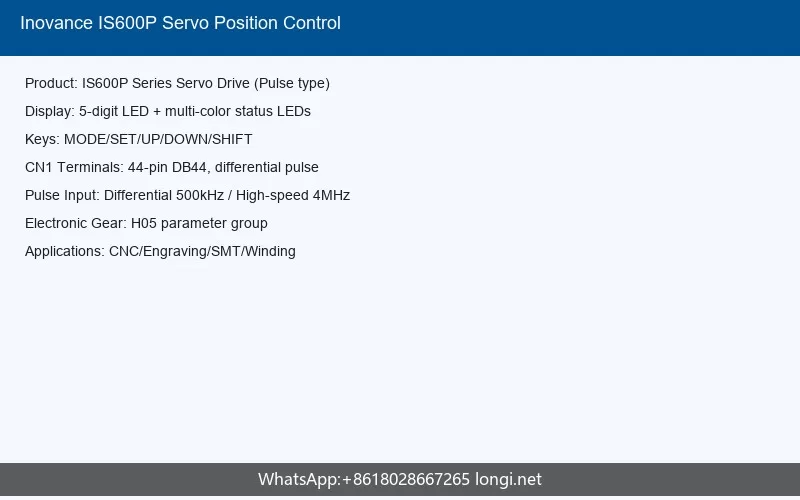
The IS600P servo drive is equipped with an LED operation panel that provides parameter configuration, status monitoring, and jog operation capabilities. The panel communicates with the drive through an RJ45 interface and can be used for both commissioning and daily operation.
1.1 LED Display and Key Functions
The operation panel features a 5-digit LED display that shows operational status, parameter codes, monitored values, and alarm codes. The display uses a hierarchical menu structure for parameter navigation:
- Group Level: Parameters are organized into functional groups prefixed with H (e.g., H00 for motor parameters, H01 for drive information, H02 for basic setup, H03 for DI terminal parameters, H05 for position control, H06 for speed control, H07 for torque control, H08 for gain adjustment, H09 for vibration suppression, H0A for auxiliary functions, H0B for monitoring, H0D for fault management).
- Function Code Level: Individual parameters within each group, identified by a two-digit suffix (e.g., H05-07 for electronic gear ratio numerator).
- Parameter Value Level: The actual setting value that can be modified.
The panel keys and their functions are:
| Key | Name | Function |
|---|---|---|
| MODE | Mode Key | Cycles between parameter setting mode, status monitoring mode, and alarm display mode |
| SET | Set/Enter Key | Confirms parameter changes; enters deeper menu levels; switches monitoring display items |
| UP Arrow | Increment Key | Increases parameter values or function code numbers |
| DOWN Arrow | Decrement Key | Decreases parameter values or function code numbers |
| SHIFT | Shift Key | Selects which digit to modify during parameter editing; cycles through monitoring items |
| JOG+/JOG- | Jog Keys | Used for jog operation to test motor rotation direction and basic functionality |
1.2 Status Display Modes
The LED panel displays different status indicators depending on the drive state:
| Display | Meaning |
|---|---|
| rdy | Drive is ready (control power and main power applied, servo OFF) |
| run | Servo is enabled and running (S-ON signal active) |
| nrd | Not ready (main power insufficient; DC bus voltage below threshold) |
| Er.xxx | Fault or warning code (xxx represents the specific code) |
| JOG | Jog operation mode is active |
In monitoring mode, the panel can display real-time values such as motor speed (H0B-00), speed command (H0B-01), torque command (H0B-02), position command counter (H0B-13), feedback pulse counter (H0B-17), bus voltage (H0B-26), AI input values (H0B-21/H0B-22), and motor angle (H0B-10).
1.3 Parameter Setting Workflow
To modify a parameter on the IS600P:
- Press MODE to enter parameter setting mode. The display shows the group number (e.g., H05).
- Use UP/DOWN to select the target group, then press SET to enter the function code level.
- Use UP/DOWN to select the function code (e.g., 07 for H05-07), then press SET to enter the value level.
- Use SHIFT to select the digit to modify, then use UP/DOWN to change the value.
- Press SET to confirm and save the value.
2. Position Mode Control with External Pulse Input
The IS600P is designed primarily as a pulse-input position control servo drive. In position mode (H02-00 = 1), the drive receives pulse commands from an external controller through the CN1 connector and executes precise positioning based on the pulse count, direction, and electronic gear ratio settings.
2.1 CN1 Terminal Overview (44-Pin DB44 Connector)
The IS600P CN1 connector is a 44-pin D-sub connector that provides all control signals including pulse inputs, digital I/O, analog I/O, and encoder divider outputs. The key terminals for position control are:
| Signal Name | Pin Number | Function |
|---|---|---|
| Low-Speed Pulse Input (Max 500k pps differential, 200k pps open collector) | ||
| PULSE+ | 41 | Pulse input positive (low-speed, differential or open collector) |
| PULSE- | 43 | Pulse input negative |
| SIGN+ | 37 | Direction signal positive |
| SIGN- | 39 | Direction signal negative |
| High-Speed Pulse Input (Max 4M pps differential) | ||
| HPULSE+ | 38 | High-speed pulse input positive |
| HPULSE- | 36 | High-speed pulse input negative |
| HSIGN+ | 42 | High-speed direction signal positive |
| HSIGN- | 40 | High-speed direction signal negative |
| Power and Common | ||
| PULLHI | 35 | External power input for open-collector pulse signals |
| GND | 29 | Signal ground |
| +24V | 17 | Internal 24V power supply (max 200mA output) |
| COM- | 14 | Common terminal for DI signals |
| Digital Inputs (DI1-DI9, programmable) | ||
| DI1-DI9 | Various | Programmable digital inputs for S-ON, ALM-RST, P-CON, etc. |
| Digital Outputs (DO1-DO5, programmable) | ||
| DO1-DO5 | Various | Programmable digital outputs for ALM, READY, etc. |
| Encoder Divider Output | ||
| PAO+/PAO- | 22/21 | A-phase output (differential) |
| PBO+/PBO- | 23/25 | B-phase output (differential) |
| PZO+/PZO- | 24/13 | Z-phase output (differential) |
2.2 Pulse Input Wiring Configurations
The IS600P supports three types of pulse input wiring, depending on the upper controller’s output capabilities:
Configuration A: Low-Speed Differential Input (Max 500k pps)
When the controller has differential line driver outputs (RS-422 compatible), connect directly to PULSE+/PULSE-/SIGN+/SIGN- terminals. This is the most reliable method for standard-speed applications.
Controller PULSE- — CN1 Pin 43 (PULSE-)
Controller SIGN+ — CN1 Pin 37 (SIGN+)
Controller SIGN- — CN1 Pin 39 (SIGN-)
Controller GND — CN1 Pin 29 (GND)
Internal 240 ohm termination resistors are built in.
Minimum pulse width: 1 microsecond
Configuration B: Low-Speed Open Collector Input (Max 200k pps)
When the controller has NPN open-collector outputs, use the internal 24V power supply or an external power supply with the PULLHI terminal.
+24V (Pin 17) — PULLHI (Pin 35)
Controller NPN output — PULSE+ (Pin 41) via 2.4k ohm resistor
Controller NPN output — SIGN+ (Pin 37) via 2.4k ohm resistor
COM- (Pin 14) — Controller common
Minimum pulse width: 2.5 microseconds
Configuration C: High-Speed Differential Input (Max 4M pps)
For high-speed applications such as CNC machining centers, use the dedicated high-speed pulse input terminals.
Controller HPULSE- — CN1 Pin 36 (HPULSE-)
Controller HSIGN+ — CN1 Pin 42 (HSIGN+)
Controller HSIGN- — CN1 Pin 40 (HSIGN-)
Controller GND — CN1 Pin 29 (GND)
Minimum pulse width: 0.125 microseconds (125 nanoseconds)
2.3 Position Mode Parameter Configuration
To configure the IS600P for position control with external pulse input, set the following parameters:
Step 1: Set control mode to position mode
Step 2: Set position command source
Step 3: Select pulse input terminal
H05-01 = 1 (High-speed pulse input port)
Note: H05-01 requires power cycling to take effect.
Step 4: Select pulse command format
H05-15 = 1 (Pulse + Direction, negative logic)
H05-15 = 2 (A/B quadrature, 4x decoding)
H05-15 = 3 (CW + CCW pulse)
Note: H05-15 requires power cycling to take effect.
Step 5: Configure servo enable (S-ON) signal
Set the terminal logic (normally open or normally closed) as needed.
2.4 Pulse Command Direction Control
The IS600P provides a position command direction switch function (FunIN.27: POSDirSel). When assigned to a DI terminal, this function allows the user to reverse the direction of position commands without changing the wiring or controller program.
Invalid (OFF) – Forward direction (default)
Valid (ON) – Reverse direction
Recommended setting: Level-triggered logic
Additionally, a pulse inhibit function (FunIN.13: INHIBIT) can be assigned to a DI terminal to temporarily disable pulse command input without disabling the servo. This is useful for pausing motion without losing position.
3. Electronic Gear Ratio Calculation and Fixed-Length Positioning Example
3.1 Electronic Gear Ratio Formula
The electronic gear ratio on the IS600P defines the scaling between the command pulse count from the controller and the actual motor encoder feedback pulses. It allows the user to match the controller’s pulse output resolution to the mechanical system’s requirements.
When H05-02 = 0 (default), the electronic gear ratio is set using numerator and denominator parameters:
The complete formula is:
— = ——————- × —
A Load Displacement per Rev n
Where:
- B (H05-07): Electronic gear ratio numerator 1 (range: 1 to 1073741824)
- A (H05-09): Electronic gear ratio denominator 1 (range: 1 to 1073741824)
- Encoder Resolution: For IS600P, the encoder resolution is 10000 pulses per revolution (2500-line encoder with 4x quadrature decoding)
- Load Displacement per Rev: The linear or rotary displacement of the load per motor revolution (in command units)
- m/n: Mechanical reduction ratio (motor rotates m revolutions, load shaft rotates n revolutions)
The IS600P also supports a second electronic gear ratio (H05-11/H05-13), which can be switched during operation using the FunIN.24 (GearRatioSel) DI function. This enables applications that require two different positioning resolutions.
3.2 Position Command Filtering
The IS600P provides two filtering options for position commands to smooth motor rotation:
| Parameter | Name | Range | Default | Description |
|---|---|---|---|---|
| H05-04 | First-order low-pass filter time constant | 0.0-6553.5 ms | 0.0 | Applies exponential smoothing to position commands; effective when pulse frequency is low or gear ratio is high (10x or more) |
| H05-06 | Average filter time constant | 0.0-128.0 ms | 0.0 | Applies moving average filtering; set to 0 to disable |
3.3 Practical Fixed-Length Positioning Example
Consider a CNC linear axis with the following specifications:
- Target movement: 100 mm
- Ball screw pitch: 10 mm per revolution (1 motor revolution = 10 mm linear travel)
- Encoder resolution: 10000 pulses per revolution (IS600P standard with 2500-line encoder, 4x quadrature)
- Desired command resolution: 1 micrometer per pulse (0.001 mm/pulse)
- No external gearbox (direct coupling, m/n = 1/1)
Step 1: Calculate required motor revolutions
Motor Revolutions = 100 mm / 10 mm per rev = 10 revolutions
Step 2: Calculate encoder feedback pulses for target movement
Encoder Pulses = 10 x 10000 = 100,000 pulses
Step 3: Calculate required command pulses from controller
Command Pulses = 100 mm / 0.001 mm = 100,000 pulses
Step 4: Calculate electronic gear ratio
B/A = 100,000 / 100,000 = 1/1
Set H05-07 (Numerator B) = 1
Set H05-09 (Denominator A) = 1
Alternative Example: 10 micrometer per pulse resolution
B/A = 100,000 / 10,000 = 10/1
Set H05-07 (Numerator B) = 10
Set H05-09 (Denominator A) = 1
Example with gearbox (reduction ratio 3:1):
Load displacement per motor rev = 10 mm x (1/3) = 3.333 mm
Encoder pulses for 100 mm = (100 / 3.333) x 10000 = 300,000 pulses
With 1 um/pulse command resolution:
Command pulses = 100,000
B/A = 300,000 / 100,000 = 3/1
Set H05-07 = 3, H05-09 = 1
Gear Ratio B/A = (E x C) / P
For IS600P (E=10000):
B/A = (10000 x C) / P
Example: P=10mm, C=0.001mm: B/A = (10000 x 0.001) / 10 = 1:1
3.4 Position Deviation Clear Function
The IS600P provides a position deviation clear function (FunIN.35: ClrPosErr) that zeros the accumulated position error. This is useful when:
- Re-establishing position reference after a mechanical adjustment
- Clearing residual position error after an emergency stop
- Preparing for a new positioning sequence
Valid (rising edge) – Position deviation cleared to zero
Invalid – Position deviation not cleared
Recommended: Assign to DI8 or DI9 terminal, set as edge-triggered
4. Fault Codes and Troubleshooting Solutions
The IS600P servo drive classifies faults and warnings into three severity levels:
- NO.1 (Class 1): Most severe – includes non-resettable faults (require drive replacement) and resettable faults (require S-ON off before reset)
- NO.2 (Class 2): Moderate severity – resettable faults (require S-ON off before reset)
- NO.3 (Class 3): Warnings – resettable without disabling servo
Faults can be reset by setting H0D-01 = 1 or using DI function FunIN.2 (ALM-RST, edge-triggered).
4.1 Class 1 Non-Resettable Faults (Drive Replacement Required)
| Code | Name | Cause | Solution |
|---|---|---|---|
| Er.101 | Parameter exception | Control power dip during parameter storage; software update; parameter write limit exceeded | Initialize system parameters (H02-31=1), re-enter all parameters; if persistent, replace drive |
| Er.102 | Programmable logic configuration fault | FPGA and MCU software version mismatch; FPGA hardware failure | Update matching FPGA/MCU software; replace drive if hardware failure |
| Er.105 | Internal program exception | EEPROM read/write anomaly; function code range exception after update | Initialize system parameters (H02-31=1), re-power; replace drive if persistent |
| Er.108 | Parameter storage fault | Cannot write to or read from EEPROM | Replace drive |
| Er.120 | Product matching fault | Motor rated current exceeds drive rated current; motor/drive model mismatch | Verify H00-00 motor code and H01-02 drive model match nameplate; replace mismatched product |
| Er.200 | Overcurrent 1 | Any phase feedback current exceeds overcurrent threshold | Check for output short circuits, motor cable faults, gain settings; replace drive if internal fault |
| Er.201 | Overcurrent 2 | Hardware overcurrent detected | Check command timing, brake resistor, motor cable, encoder wiring; replace drive if persistent |
| Er.210 | Output ground short | Motor cable or motor winding shorted to ground | Measure insulation resistance of U/V/W to PE; replace cable or motor; replace drive if internal fault |
| Er.234 | Runaway (motor flying) | UVW phase sequence error; encoder wiring error; encoder model mismatch; excessive vertical axis load | Correct UVW wiring; verify encoder connection; check H00-00 motor code; adjust brake parameters for vertical axes |
| Er.430 | Control power undervoltage | Control power (L1C/L2C) below threshold (220V drive: below 190V DC; 380V drive: below 350V DC) | Check control power voltage; ensure stable power supply; replace drive if persistent |
4.2 Class 1 and Class 2 Resettable Faults
| Code | Name | Class | Cause | Solution |
|---|---|---|---|---|
| Er.130 | DI function duplicate assignment | NO.1 | Same DI function assigned to multiple terminals; DI function number exceeds available count | Check H03 group parameters; reassign unique DI function numbers; power cycle |
| Er.131 | DO function assignment exceeded | NO.1 | DO function number exceeds available count (after software update) | Initialize system parameters (H02-31=1); re-power |
| Er.400 | Main power overvoltage | NO.1 | DC bus voltage exceeds threshold (220V: above 420V; 380V: above 760V); input voltage too high; brake resistor failure | Check input voltage; verify brake resistor connection and resistance value; increase deceleration time; set H02-26/H02-27 for external resistor |
| Er.410 | Main power undervoltage | NO.1/NO.2 | DC bus voltage below threshold (220V: below 200V; 380V: below 380V); power dip; phase loss | Check input voltage; verify three-phase power; check H0A-00 phase loss detection setting |
| Er.420 | Main power phase loss | NO.2 | Three-phase drive running on single-phase power; loose input wiring; unbalanced three-phase voltage | Check and tighten R/S/T wiring; verify three-phase voltage balance; for 0.75kW three-phase drive, set H0A-00=2 to disable phase loss protection |
| Er.500 | Overspeed | NO.1 | Motor speed exceeds overspeed threshold (1.2x max motor speed or H0A-08 setting); UVW sequence error; command exceeds limit | Check UVW wiring; verify command frequency vs. overspeed threshold; reduce pulse frequency or gear ratio; adjust H0A-08 |
| Er.510 | Pulse output overspeed | NO.2 | Encoder divider output frequency exceeds 2 MHz hardware limit | Reduce H05-17 (encoder divider pulse count); reduce input pulse frequency |
| Er.610 | Drive overload | NO.2 | Accumulated drive heat exceeds threshold; excessive load; insufficient cooling | Reduce load; improve cooling; check motor and mechanical system; use larger capacity drive |
| Er.620 | Motor overload | NO.2 | Accumulated motor heat exceeds threshold; motor wiring/encoder error; excessive load | Check motor and encoder wiring; reduce load; verify motor parameter settings |
| Er.630 | Motor stall | NO.2 | Motor blocked; excessive load torque; UVW wiring error | Check mechanical system for jamming; verify UVW wiring; reduce load |
| Er.650 | Heatsink overheat | NO.2 | Ambient temperature too high; cooling fan failure; blocked air duct | Reduce ambient temperature; replace cooling fan; clean air duct |
| Er.602 | Angle identification failure | NO.1 | Encoder communication error; motor cable disconnection; encoder model mismatch | Check encoder wiring; verify motor code H00-00; ensure motor cable connected |
4.3 Position Control Specific Faults
| Code | Name | Class | Cause | Solution |
|---|---|---|---|---|
| Er.B00 | Excessive position deviation | NO.2 | Position deviation exceeds allowable limit; excessive load; gain too low; command frequency too high | Increase position deviation limit; perform gain adjustment; reduce command frequency; check mechanical system |
| Er.B01 | Pulse input abnormal | NO.2 | Pulse input frequency exceeds hardware limit; pulse input wiring noise; incorrect pulse format setting | Verify pulse frequency within limits; check H05-15 pulse format setting; use twisted-pair shielded cable; increase filter time constant H0A-24/H0A-30 |
| Er.B03 | Electronic gear ratio exceeded | NO.2 | H05-07/H05-09 or H05-11/H05-13 set beyond valid range; resulting gear ratio too large or too small | Verify gear ratio calculation; ensure numerator and denominator within 1-1073741824 range; check resulting ratio is reasonable |
| Er.121 | Servo ON command invalid | NO.2 | Redundant servo enable signal when using internal enable function (H0D-02/H0D-03/H0D-12) | Disable external S-ON signal when using internal enable; set DI function 1 to invalid |
4.4 Warnings (Class 3, Resettable Without Disabling Servo)
| Code | Name | Cause | Solution |
|---|---|---|---|
| Er.110 | Divider pulse output setting fault | H05-17 setting incompatible with encoder resolution | Set H05-17 within valid range (35-32767) |
| Er.909 | Motor overload warning | Motor load approaching overload threshold | Reduce load; check mechanical system; monitor motor temperature |
| Er.920 | Brake resistor overload | Regenerative energy exceeds brake resistor capacity | Increase deceleration time; use larger brake resistor; verify H02-26/H02-27 settings |
| Er.939 | Motor power cable disconnection | Motor cable (U/V/W) loose or disconnected | Check and tighten motor cable connections |
| Er.941 | Parameter change requires power cycle | Parameter modified that requires re-powering to take effect | Power cycle the drive (disconnect L1C/L2C, reconnect) |
| Er.950 | Forward overtravel warning | Forward overtravel limit switch (P-OT) activated | Move axis in reverse direction; check overtravel switch wiring |
| Er.952 | Reverse overtravel warning | Reverse overtravel limit switch (N-OT) activated | Move axis in forward direction; check overtravel switch wiring |
| Er.990 | Input phase loss warning | One phase of three-phase input power lost or severely unbalanced | Check three-phase input voltage; verify R/S/T wiring |
4.5 Startup Troubleshooting for Position Mode
When the motor does not rotate after inputting position commands, check the following:
- Verify panel status: The panel should display “run” (not “rdy”). If “rdy”, check S-ON signal wiring and H03 group DI settings.
- Check position command counter: Monitor H0B-13 (input position command counter). If it remains 0, no pulse is being received.
- Verify H05-00 = 0 (pulse command source)
- Verify H05-01 matches the physical wiring (low-speed or high-speed port)
- Check pulse input wiring (PULSE+/PULSE-/SIGN+/SIGN- or HPULSE+/HPULSE-/HSIGN+/HSIGN-)
- Check if FunIN.13 (INHIBIT) or FunIN.37 (PulseInhibit) is active, blocking pulse input
- Check direction reversal: If H0B-13 shows a negative value, verify:
- H05-15 (pulse format) matches the actual pulse output format from the controller
- FunIN.27 (POSDirSel) direction switch is not accidentally activated
- H02-02 (motor rotation direction) is set correctly
- Check positioning accuracy: If positioning is inaccurate, verify the relationship:
Pout = Pin (output command = input command)
Pin x Gear Ratio = Pf (input command x gear ratio = feedback pulses)
Pf x Delta_L = PL (feedback pulses x displacement per pulse = mechanical position)If Pout != Pin: Check pulse input wiring for noise (use twisted-pair shielded cable)
If Pin x Ratio != Pf: Check if servo was disabled during motion or position deviation was cleared
If Pf x Delta_L != PL: Check for mechanical slippage between motor and load
4.6 Fault Reset Procedure
To reset faults on the IS600P:
- For NO.1 and NO.2 faults: First disable the servo (S-ON off), then either:
- Set H0D-01 = 1 (fault reset), or
- Trigger DI function FunIN.2 (ALM-RST) with a pulse of at least 3 ms duration
- For NO.3 warnings: Directly set H0D-01 = 1 or trigger FunIN.2 (no need to disable servo first).
- For parameters requiring power cycle: If the fault is related to a parameter change, disconnect and reconnect control power (L1C/L2C) after modifying the parameter.
5. Commissioning and Maintenance
5.1 Initial Commissioning Steps
- Power-on check: Apply control power (L1C/L2C) and main power (R/S/T or L1/L2). The panel should display “rdy”.
- JOG test: Use the panel JOG function to verify motor rotation direction. If reversed, either swap U/V/W wiring or change H02-02.
- Inertia identification: Perform load inertia identification (H08-15) if the load inertia ratio is unknown. This can be done via the IS-Opera software or panel parameters.
- Gain adjustment: Use auto gain adjustment or manually set the rigidity level (H08-00) based on the application requirements.
- Position accuracy verification: Send a known pulse count and verify the mechanical displacement matches the calculation.
5.2 IS-Opera Software
The IS600P is supported by the IS-Opera PC software (available from www.inovance.cn), which provides:
- Oscilloscope for real-time signal monitoring
- Parameter management (batch read/write)
- Inertia identification with guided motion sequences
- Mechanical resonance analysis
- JOG motion planning
- Gain adjustment with visual feedback
- Electronic cam configuration (for supported models)
Communication is via the standard PC communication cable (S6-L-T00-3.0) or a self-made cable following the wiring specification in the manual.