
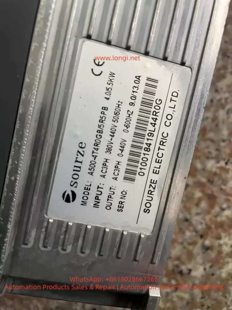
SOURZE inverters are high-cost-performance devices in the field of industrial automation, widely used in fans, water pumps, machine tools, conveyor lines, and other scenarios. However, the frequent occurrence of the ERR15 fault code during use is a major headache for many maintenance personnel. This article takes the “Drive Overheat” fault (ERR15) of the SOURZE A500/A500S series inverter as the core, combining official manual fault tables, actual installation environments, parameter settings, and heat dissipation principles to systematically explain the fault causes, diagnostic steps, complete solutions, and long-term prevention strategies. Whether you are a field engineer, equipment purchaser, or factory electrician, you will find actionable solutions to avoid repeated tripping and production losses.
1. What does the ERR15 fault code actually mean?
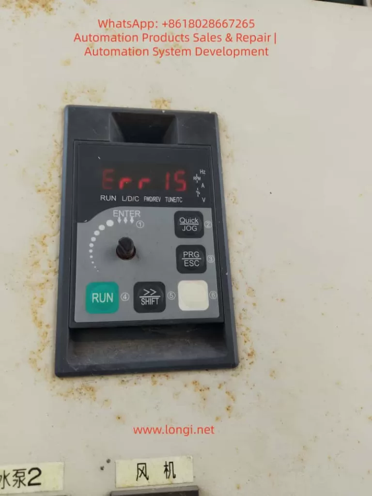
On the SOURZE A500/A500S general vector control inverter, when the operation panel displays “Err 15” or “Err15”, the system immediately enters protection mode, stops output, the panel red light flashes, and the fault relay acts to alarm.
- Official Definition: Page 136 of the manual clearly states: Err15 = Drive Overheat (Inverter Overheat).
- Core Distinction: This is not motor overheat (Err14), nor is it drive overload (Err13). It means the internal power module (IGBT) or heat dissipation system temperature of the inverter has exceeded the protection threshold.
- Trigger Mechanism: The built-in NTC thermistor monitors the heat sink temperature in real-time. Once it reaches the threshold (usually 85-105°C, depending on power), protection is triggered immediately.
- High-Incidence Scenarios: Listed on page 176 of the manual, ERR15 is a high-frequency fault alongside overvoltage, undervoltage, and overload. The inverter is essentially a high-frequency switching power supply, generating significant heat during operation (switching loss + conduction loss + harmonic loss). It accounts for over 30% of faults in high-temperature summer, dusty environments, and heavy-load fan/pump applications.
2. Deep Analysis of the 5 Root Causes of ERR15
According to the fault diagnosis table on page 136 of the official SOURZE manual, there are exactly 5 causes for ERR15. Based on industry maintenance data, they are ranked by probability as follows:
Cause 1: High Ambient Temperature (Approx. 35%)
- Phenomenon: The rated operating temperature is usually -10°C to 40°C (no derating). Above 40°C, derating is required. In summer, workshop temperatures can exceed 45°C, or if installed in a closed cabinet without ventilation, the heat sink surface temperature easily breaches the protection value.
- Principle: The junction temperature of the IGBT module halves its lifespan for every 10°C increase. Manual section 2.4 specifies: higher carrier frequency and larger output current result in more internal heat.
Cause 2: Air Duct Blockage (Approx. 28%)
- Phenomenon: The inverter uses forced air cooling. Inlets/outlets get blocked by dust, lint, or oil, obstructing airflow. Common in textile mills, painting workshops, and grain processing plants.
- Consequence: Heat dissipation efficiency drops by over 70% after blockage, triggering ERR15 within 5-10 minutes.
Cause 3: Cooling Fan Failure (Approx. 20%)
- Phenomenon: Fan bearing wear, blade breakage, motor coil burnout, or capacitor aging cause speed reduction or total stoppage.
- Lifespan: A500 series fans are DC brushless or AC types. Bearing grease drying up after 3-5 years is a common failure point. Manual section 2.7 requires fan inspection every 6 months.
Cause 4: Module Thermistor Damage (Approx. 10%)
- Phenomenon: NTC thermistor aging, desoldering, or resistance drift causes incorrect temperature sampling (false alarm or missed alarm).
- Data: In some old models, resistance drifts from 10kΩ to over 20kΩ after high-temperature cycles, causing the system to falsely judge overheat.
Cause 5: Inverter Module (IGBT) Damage (Approx. 7%)
- Phenomenon: IGBT chip breakdown, wire bond detachment, or internal module short circuit causes local hot spots. Even with normal fans and ambient temp, the module itself heats abnormally.
- Nature: This is a hardware failure requiring replacement of the entire power module.
Note: The manual reminds that undersized inverter selection (listed under other faults like overload) can indirectly cause ERR15 if running at heavy load long-term.
3. Complete Diagnostic Process for ERR15 (10 Steps, Locate in 5 Minutes)
Safety First: Do not disassemble immediately! Follow this standardized process:
- Safety: Disconnect main power, wait >10 minutes for discharge (Manual 1.1). Verify DC bus voltage <36V with a multimeter.
- Read Records: Power on, enter U0 group monitoring parameters. Check U0-01 (last fault type), U0-02 (current fault type), U0-03 (frequency/current/voltage at fault).
- Check Environment: Measure heat sink surface temp with an infrared thermometer. If environment >40°C or heat sink >80°C, proceed to “Cause 1”.
- Visual Inspection: Power off, remove panel. Check inlets/outlets for blockages. Shine a flashlight to confirm air duct is clear.
- Test Fan: Power on (no load), listen for fan sound, feel airflow. If silent/weak/slow, measure fan power supply (DC12V/24V) with multimeter.
- Measure Thermistor: Power off. Locate NTC near power module (usually 2 pins). Resistance should be ~10kΩ at 25°C. If infinite or 0Ω, it is damaged.
- Judge IGBT Module: Use multimeter diode test to measure IGBT pin forward/reverse voltage drop (normal 0.3-0.7V). Short or open circuit indicates module damage.
- Review Parameters: Check A7 group carrier frequency (default 6-8kHz). If set to 15kHz under heavy load, reduce immediately.
- Check Load: Confirm motor rated current ≤ inverter rated output current. Manual 2.3 shows: G-type 150% overload for 60s, P-type 120% overload for 60s.
- Restart Verification: Clear fault (press PRG+ESC), run no-load and observe if temperature drops.
4. Targeted Solutions for ERR15
Solution 1: High Ambient Temperature
- Immediate Cooling: Install AC or exhaust fan to keep cabinet temp <35°C.
- Derating: If cooling is impossible, derate 1% per 1°C rise per manual 2.4. E.g., at 45°C, derate by 10%.
- Long-term: Upgrade heat sink or use hybrid air-water cooled cabinet.
Solution 2: Air Duct Blockage
- Thorough Cleaning: Use compressed air (<0.2MPa) or soft brush to remove dust. Do not wash with water!
- Install Filter: SOURZE optional part, or buy IP5X filter externally. Clean monthly.
- Optimize Position: Manual 3.1 requires 20cm space above/below, 10cm left/right. Avoid heat sources.
Solution 3: Fan Failure
- Replace: Original fan models vary by power (e.g., 4T011G uses FAN-01). Available from SOURZE dealers (~50-200 RMB).
- Steps: Power off → Remove panel → Unplug fan → Unscrew → Install new fan → Power on to test speed.
- Prevention: Manual 2.7 recommends replacing bearing grease annually or replacing the fan entirely.
Solution 4: Thermistor Damage
- Replace NTC: Usually 2-3 NTCs on module. Buy same resistance (B-value 3950) replacement. Solder with ESD protection.
- Temporary Fix: Parallel/series precision resistor for correction (not recommended long-term).
- Upgrade: Some old models can have E-group parameters flashed to optimize threshold (requires factory authorization).
Solution 5: Inverter Module Damage
- Replace Whole Unit: Must replace entire IPM module (IGBT+Driver). Model e.g., 4T011G corresponds to MG300J2YS50.
- Requirement: Must be done by qualified electrician. Reapply thermal grease, tighten screws to 4-6Nm torque.
- Post-Replacement: Perform manual 4.8 motor parameter self-learning (static/rotary tuning) to avoid new faults.
5. Cooling System Principle & Parameter Optimization
A500 series uses “Aluminum Heat Sink + Forced Air Cooling”.
- Heat Formula: Switching loss Psw=21×Udc×Ic×(ton+toff)×fsw, Conduction loss Pcond=Ic×Vce(sat).
- Key Parameter: Carrier frequency (A7-00) from 2kHz to 15kHz increases heat by 3x!
Optimization Tips:
- Set 2-4kHz for heavy-load/low-frequency, 8-10kHz for light-load/high-speed.
- Enable Auto Carrier Adjustment (A7-01=1).
- Enable “Fast Current Limit” (E2 group) to reduce overcurrent heating.
- Avoid frequent acceleration/deceleration during PID control (Manual AA group).
6. Hardcore Installation Precautions (Manual Essence)
Manual Chapter 1 (Safety) + Chapter 3 (Installation):
- Install in metal flame-retardant cabinet, away from combustibles.
- Strictly Prohibit connecting capacitors/surge suppressors on output side (causes instant overcurrent).
- Grounding must be standard (PE wire cross-section ≥ power line).
- Derate if altitude >1000m (Manual 1.2.11).
- Install lightning arrester in lightning-prone areas.
7. Routine Maintenance & ERR15 Prevention System (6-Month Schedule)
- Monthly: Clean air duct + filter.
- Quarterly: Check heat sink temp with thermal gun <70°C.
- Semi-Annually: Replace fan grease or entire fan; check thermistor resistance.
- Annually: Dust entire unit + tighten all screws + motor insulation test (≥5MΩ).
- Logs: Create U1 group monitoring Excel, record output current and temperature trends.
- Spares: Keep 1 fan + 1 NTC + 1 set of thermal grease per device.
8. Real Case Studies (3 Typical Scenarios)
Case 1: Textile Mill Fan ERR15 Repeated Alarm
- Issue: Heavy dust, air duct blocked weekly.
- Solution: Install special dust filter + weekly compressed air cleaning. Failure rate dropped from 3/month to 0.
Case 2: Water Pump Station Summer ERR15
- Issue: Workshop 45°C, cabinet internal temp 52°C.
- Solution: Install cabinet AC + reduce carrier frequency from 12kHz to 6kHz + derate 5%. Problem solved.
Case 3: Old Equipment IGBT Module Damage
- Issue: After 8 years operation, ERR15 appeared suddenly.
- Solution: Replace module + re-learn parameters + upgrade fan. Equipment returned to stable operation.
9. Professional Repair Advice & Safety Red Lines
- User Boundary: Users should only troubleshoot first 3 causes (Environment, Duct, Fan). For the last 2, contact SOURZE authorized service.
- Safety: Maintenance requires power off >10 mins, wear ESD wrist strap.
- Post-Replacement Test: Insulation test + 24-hour no-load observation required after module change.
- Strictly Prohibit: Do not modify E-group factory parameters (Manual 5.16).
10. Frequently Asked Questions (FAQ)
Q1: Difference between ERR15 and Err14?
A: Err14 is Motor Overheat (thermal relay or A1-07 protection). Err15 is Inverter Overheat.
Q2: Can I use it after cleaning dust?
A: Yes for minor blockage, but check fan and temperature simultaneously.
Q3: Can I shield ERR15 protection?
A: Absolutely NO! Manual A9 group defaults to non-shieldable. Forcing it will burn the module.
Q4: New machine gets ERR15 immediately?
A: 99% due to improper installation or high ambient temp. Recheck Manual 3.1 dimensions.
Q5: Still alarms after fan replacement?
A: Check thermistor or module. 90% chance it’s one of these two.
Q6: How to check historical fault count?
A: U0-04 records fault count (last 8 times max).
Q7: Same ERR15 threshold for P-type and G-type?
A: Yes, but P-type has weaker overload capacity, more prone to overheat under heavy load.
Q8: Prevention at high altitude?
A: Derate + enhance ventilation. Consult SOURZE support if needed.
Q9: Does motor keep rotating after ERR15?
A: Stops immediately. Restart after clearing fault.
Q10: Handling ERR15 during warranty?
A: Provide fault records + parameter screenshots. Contact local agent for free inspection/replacement (if not man-made).
Conclusion: Nip ERR15 in the Bud
SOURZE A500/A500S inverters are highly reliable. 99% of ERR15 faults stem from “Environment + Maintenance” issues. By strictly following manual installation specs, daily cleaning, parameter optimization, and temperature monitoring, you can reduce ERR15 rate to near zero. Prevention is always cheaper than repair—one module replacement can cost 30% of the device price.
If you are facing ERR15 alarms, feel free to reply with your inverter model, power, application scenario, ambient temperature, and current/frequency at fault. I can provide a precise one-on-one diagnosis plan. Let’s keep equipment stable and factories productive!