Huazhong CNC HNC-210A/HNC-210B Manual Guide: Operator Panel, I/O Wiring, Servo and Spindle Connection, PLC Addresses, G-Code Interlocks and Fault Diagnosis
HNC-210 Commissioning Is About the Whole Machine Link
HNC-210 is an open-architecture CNC unit with an industrial PC, 32-bit processor, feed-axis interfaces, spindle interface, handheld unit interface, embedded PLC and Ethernet expansion. HNC-210A supports up to four pulse axes. HNC-210B supports up to eight pulse axes.
For retrofit and repair work, the key is not one menu or one parameter. The real system is made from CNC, servo drives, spindle drive, I/O terminal boards, emergency stop circuit, overtravel circuit and PLC ladder logic. Wiring tells where the signal goes; PLC logic tells why the machine allows or blocks motion. Both must be checked together.
Panel and Handheld Unit
The machine operation panel and handheld unit provide mode selection, axis selection, override, emergency stop, cycle start, feed hold and handwheel jog. Before changing parameters, check mode, E-stop state, feed override, spindle override, handheld connection and panel indicators.
The manual explains that E-stop buttons on the panel and handheld unit are wired into the safety circuit. Additional E-stop buttons may be added. Their normally closed contacts should be connected in series. When any E-stop is pressed, relay KA2 drops out, cutting power or enable to feed axes, spindle, tool changer or turret, while an auxiliary contact feeds the PLC alarm input.
Digital I/O and Terminal Boards
HNC-210 can use digital input/output interfaces and terminal boards. Typical ranges include X0.0-X7.3 inputs and Y0.0-Y5.7 outputs, plus handheld inputs X8.0-X8.6, E-stop X8.7 and handheld outputs Y6.0-Y6.3.
Diagnose I/O in this order: field switch, terminal LED, CNC input address, PLC logic, CNC output address, relay or solenoid. Measuring 24 V on a wire is not enough; the CNC diagnosis page must show that the address changed.
Feed-Axis Servo Connection Through XS30-XS37
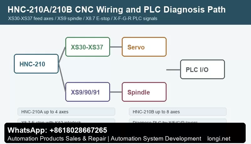
HNC-210A provides up to four pulse-axis connectors XS30-XS33. HNC-210B/C provides up to eight connectors XS30-XS37. Each axis outputs command pulse CP+/CP- and direction DIR+/DIR- to a servo or stepper drive, with related ready or mode signals.
With pulse-interface servo drives, the position loop is usually inside the servo drive. HNC-210 sends command pulses. Full closed-loop control requires a suitable servo drive with full-closed-loop feedback. Electronic gear ratio, servo gain, alarm output and in-position signals are still configured in the servo drive.
Spindle Interfaces XS9, XS90 and XS91
The spindle side includes XS9 SPDL.0, XS90 SPDL.1 encoder and XS91 SPDL1 I/O. Common signals include X3.0 alarm input, X3.1 speed arrival, X3.2 zero-speed arrival, X3.3 orientation complete, Y1.0 forward, Y1.1 reverse, Y1.2 enable, Y1.3 orientation, AOUT1 -10 V to +10 V and AOUT2 0 V to +10 V.
For inverter spindles, check analog speed output, forward/reverse outputs, enable, alarm input and speed arrival. For servo spindles, also check orientation complete, zero speed and encoder feedback. Threading and rigid tapping require correct spindle encoder feedback.
E-Stop and Overtravel
X8.7 is the E-stop input. KA2 is used for power/enable interlock of servo and spindle circuits. Y0.7 is shown in the manual example as overtravel release output. Overtravel limit switches use normally closed contacts in the overtravel chain and normally open contacts into PLC inputs so the system can identify the axis and direction.
Do not bypass E-stop or limit circuits just to clear an alarm. Check X8.7, limit input addresses, KA2 coil, KA2 auxiliary contact, Y0.7 output and the PLC alarm bit to determine whether the problem is the safety chain, PLC condition or servo alarm.
PLC Signal Classes: X/F/G/Y/R/D
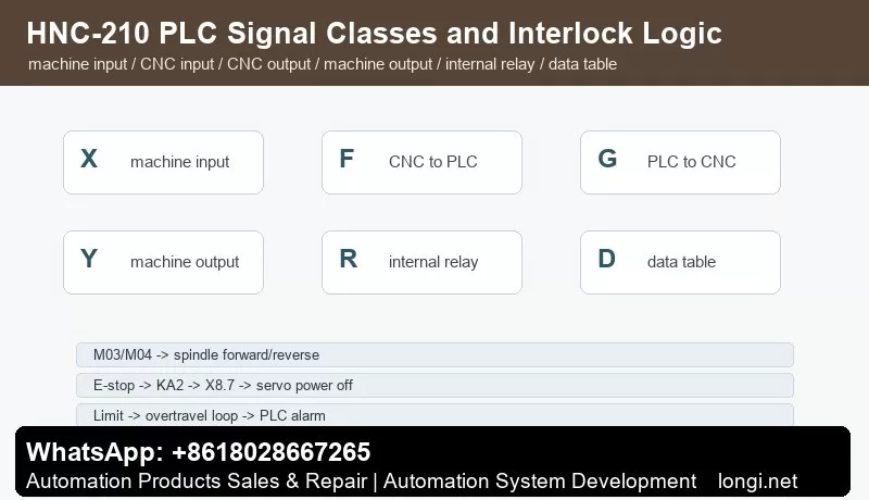
The PLC programming manual separates machine inputs, CNC-to-PLC signals, PLC-to-CNC signals, machine outputs, internal relays and data tables. A practical way to read the ladder is X/F/G/Y/R/D: X for field inputs, Y for field outputs, F for CNC-to-PLC system signals, G for PLC-to-CNC status/control, R for internal relays and D/data table for stored states such as tool data.
For M03, CNC sends a spindle-forward request to PLC. PLC checks E-stop, alarm, lubrication, clamp, spindle-drive ready and door interlock. If conditions are satisfied, it outputs Y1.0 and Y1.2 and waits for X3.1 speed arrival. An M code is not just one output bit; it is a request filtered by the PLC safety chain.
Simple G-Code Interlock Example
“`gcode
M03 S800
G04 X2.0
G01 X50.0 F100
M05
“`
Behind this short program, the PLC must enable spindle forward, send analog speed reference, wait for speed arrival, allow feed, stop spindle output and confirm zero speed or braking. If the program stops after M03, check speed arrival, alarm input, enable output and the PLC waiting condition.
Fault Diagnosis
Axis does not move: check X8.7, KA2, servo ready, XS30-XS37, CP/DIR output, axis parameters and drive alarms.
Spindle does not run: check M03/M04 request, Y1.0/Y1.1/Y1.2, AOUT1/AOUT2, X3.0 alarm, X3.1 speed arrival, spindle-drive enable and analog common.
Homing direction is wrong: check axis direction parameter, drive direction, home switch address, limit state, homing mode and PLC permission.
E-stop cannot reset: check all E-stop NC contacts, KA2 coil, KA2 auxiliary contact, X8.7 diagnosis and PLC reset conditions.
Overtravel release does not work: check limit NC chain, limit feedback, Y0.7 output, overtravel-release button, reverse jog direction and PLC latch.
Tool changer loses tool number: check tool-position switches, spindle clamp/unclamp, tool data table, current spindle tool number, internal relays and power-loss recovery logic.
The practical rule for HNC-210A/HNC-210B is: confirm hardware by connector, confirm I/O by X/Y addresses, read PLC logic by F/G/R/D layers, then verify the motion chain with short G-code tests.