1. Background and Practical Repair Challenges
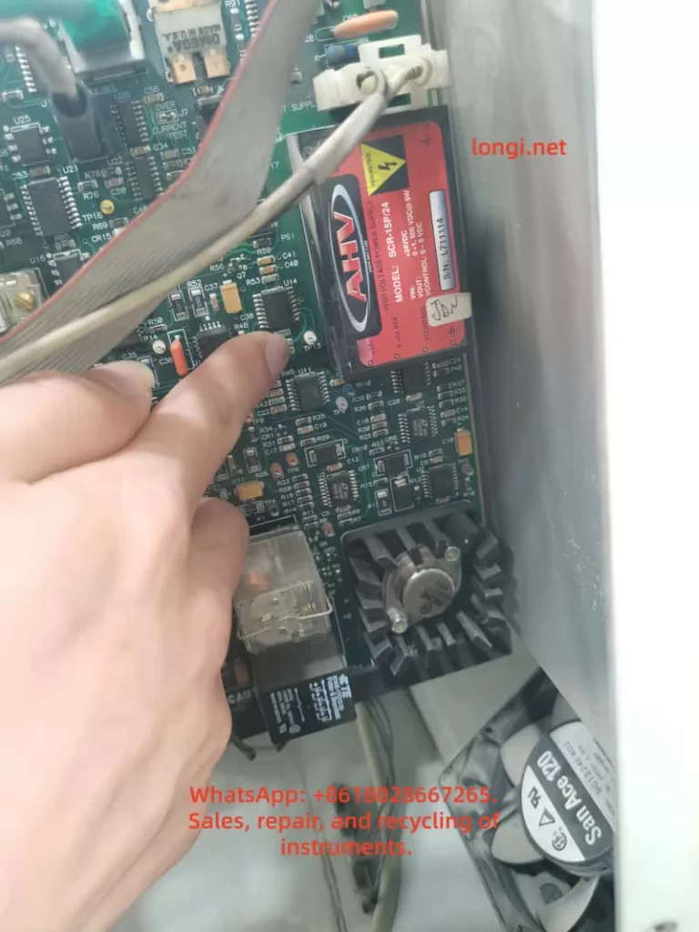
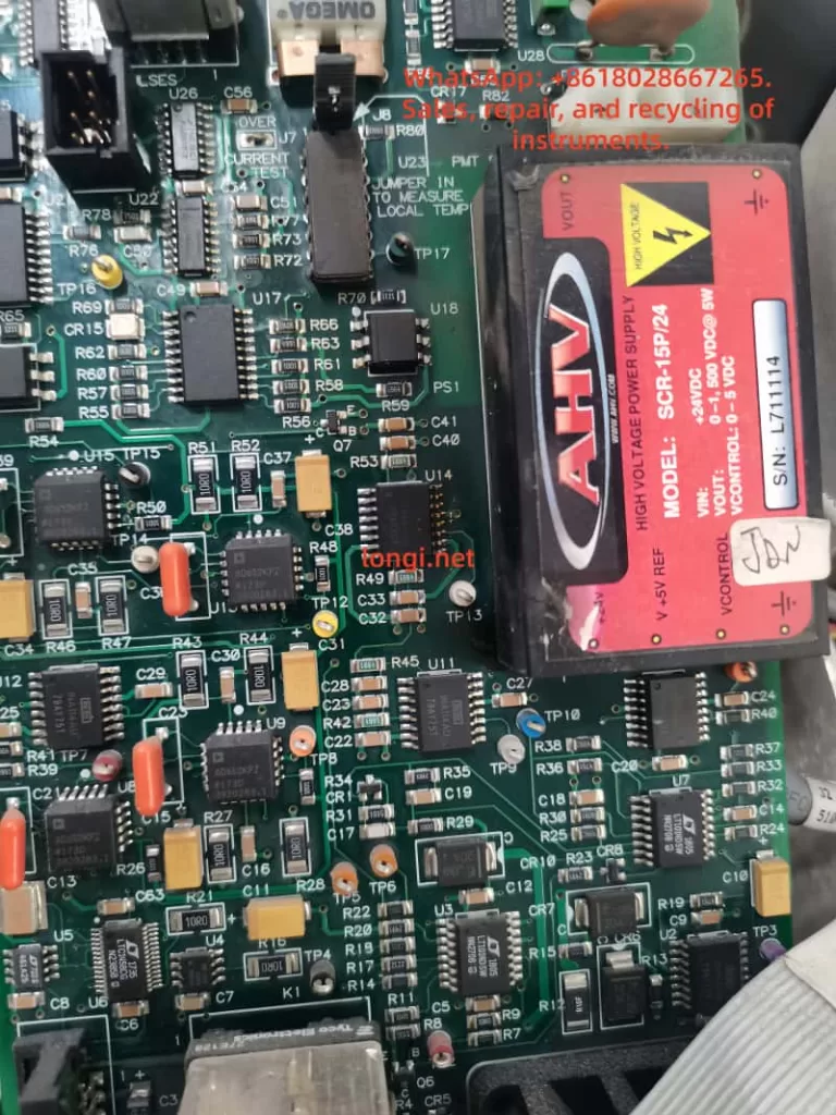
RF drivers manufactured by Gooch & Housego and similar companies are widely used in laser processing systems, acousto-optic modulators, optical measurement instruments, fiber laser systems, laboratory equipment, and precision motion or beam-control applications.
These RF drivers are normally designed to drive AOMs, AO deflectors, or other loads requiring a stable RF excitation source. In many systems, the RF driver runs at a fixed carrier frequency while an external modulation input controls whether the RF output is enabled, disabled, or amplitude-modulated.
This article uses the Gooch & Housego 1200AF-DINA-2.5 HCR RF driver as an example. The discussed fault condition is a common field failure: the external AM IN port was incorrectly connected to a 24 V industrial control signal, causing damage to the modulation input circuit. After repair, the main question becomes: how can a technician safely verify that the AM IN function, RF switching path, and RF output path have been restored when only basic instruments are available?
The difficulty is not simply whether the unit powers up. A correct repair verification requires answering several technical questions:
- What is the correct DC supply voltage for the RF driver?
- Is AM IN a 24 V industrial control input, a TTL input, or an analog modulation input?
- How should the RF output be terminated during test?
- Can a normal oscilloscope probe be connected directly to the RF output?
- How can RF output activity be confirmed without an RF power meter or spectrum analyzer?
- How should a simple detector circuit be connected?
- What conditions prove that AM IN actually controls the RF output?
A proper test sequence should follow the logic below:
Verify correct DC supply
→ Connect a suitable RF load
→ Apply the correct AM IN control voltage
→ Convert RF output into a low-frequency or DC detector signal
→ Compare RF output at AM IN low and high states
→ Apply square-wave modulation and verify synchronized switching
Only after this chain has been verified can the technician reasonably conclude that the AM IN interface, control logic, RF generation path, RF power amplifier, and RF output path are operating normally.
2. Main Interfaces and Operating Principle
The front panel of this type of RF driver normally includes three important electrical connections:
AM IN
Vcc +24V
RF OUTPUT
Their functions are different:
Vcc +24V: Main DC supply input.AM IN: External modulation or RF-enable control input.RF OUTPUT: RF power output to the AOM, AO device, or matched RF test load.
The internal architecture of a typical fixed-frequency RF driver can be simplified as follows:
24 V DC input
↓
Internal DC regulation and bias circuits
↓
RF oscillator or frequency source
↓
RF enable / modulation control circuit
↓
RF pre-amplifier stage
↓
RF power amplifier stage
↓
RF OUTPUT connector
The AM IN port is not a power supply terminal. It is a control input. Depending on the model, AM IN may be an analog modulation input, a digital enable input, a TTL input, or a logic-controlled RF switching input.
For a model identified as DINA, the practical testing approach should normally follow a digital-input logic method. In other words:
Low level → RF output disabled or strongly reduced
High level → RF output enabled
For initial testing, the safest control levels are generally:
Low level: 0 V
High level: approximately +3.3 V to +5 V
A 24 V industrial control signal must not be applied directly to this port unless the manufacturer explicitly specifies a 24 V input rating.
3. Why Applying 24 V to AM IN Can Damage the Driver
In industrial equipment, technicians often encounter 24 V PLC outputs, relay outputs, photoelectric sensors, solenoid control circuits, and other standard 24 VDC control systems. Because the RF driver has an interface labeled “AM IN,” it may be incorrectly assumed that this port can accept an industrial-level input signal.
That assumption can destroy the input circuit.
The AM IN port may internally connect to one or more of the following circuits:
- TTL logic input buffer;
- CMOS digital input;
- comparator input;
- transistor switching stage;
- optocoupler input;
- RF-enable control transistor;
- PIN diode bias circuit;
- RF gain-control circuit;
- ESD protection diode network;
- logic gate or pulse-shaping stage.
Many of these components are designed for low-voltage logic operation.
Typical limits may be approximately:
TTL input: normally 0 V to 5 V
CMOS input: normally 0 V to 3.3 V or 5 V
Comparator input: limited by supply rails
Small-signal transistor junctions: low reverse-voltage tolerance
ESD clamp diode: damaged if high current is forced through it
When 24 V is directly injected into AM IN, the failure path may be:
24 V applied to AM IN
↓
Input series resistor overheats or burns
↓
Protection diode becomes shorted or open
↓
Logic IC input pin is damaged
↓
Control transistor is punctured
↓
RF enable command becomes abnormal
↓
RF output stays permanently OFF, permanently ON, unstable, or intermittent
For this reason, repairing the visibly damaged resistor or diode may not be sufficient. The technician should also verify whether the following stages still work:
AM IN voltage recognition
↓
Logic-level conversion
↓
RF enable switching
↓
RF oscillator control
↓
RF power amplifier enable chain
4. Why the Internal RF Power Module Gets Hot
Inside the RF driver, there may be a wideband RF power amplifier module, such as an RFHIC module or another hybrid RF amplifier block. This component is not a normal digital IC or low-power transistor. It is a high-frequency RF power amplifier.
Such modules may operate with characteristics similar to:
Supply voltage: 24 VDC
Frequency range: tens of MHz to hundreds of MHz or higher
Output capability: several watts
Quiescent current: hundreds of milliamps
Even with no full RF output, the amplifier may consume significant current due to bias circuits and RF amplifier operating conditions.
For example:
24 V × 0.6 A = 14.4 W
Much of that energy becomes heat.
Therefore, it is normal for an RF power amplifier module to become warm or hot after power is applied. However, the technician must distinguish between normal heating and abnormal overheating.
Normal heating conditions
- The module warms gradually after power-on.
- The metal heat spreader becomes noticeably warm after one or several minutes.
- DC current remains stable.
- The RF load is correctly connected.
- Temperature rise is controlled and repeatable.
- AM IN switching causes only moderate changes in current or temperature.
Abnormal heating conditions
- The module becomes extremely hot within a few seconds.
- The power supply immediately enters current limit.
- The current is much higher than expected.
- The RF output is left open or badly mismatched.
- The RF amplifier remains fully enabled even when AM IN is low.
- The module heats strongly even with no valid RF activity.
- There is visible discoloration, smoke, smell, or abnormal noise.
The RF power amplifier must be firmly attached to its aluminum heat sink or metal chassis. If the module is tested without proper thermal contact, thermal grease, thermal pad, or mechanical pressure, it may overheat rapidly and be damaged.
5. Why RF OUTPUT Must Be Connected to a Load
The RF output of this driver is not a normal DC output. It is a high-frequency RF source, typically designed around a 50 Ω transmission system.
Most RF cables, RF test instruments, spectrum analyzers, RF power meters, directional couplers, and RF amplifier outputs use 50 Ω as the standard impedance.
Therefore, the correct RF load should be:
50 Ω
The correct connection is:
SMA center pin
↓
50 Ω load resistor
↓
SMA outer shell / RF ground
The resistor must be connected across the RF center conductor and RF ground. It is not placed in series with the line.
A correct physical arrangement is:
SMA center pin ── 50 Ω resistor ── SMA outer shell
The SMA outer shell is the RF return path. It is normally connected to the RF ground, chassis ground, and usually the DC supply negative reference.
There is no need to connect the resistor separately to building earth or protective earth. The critical connection is from the RF center pin to the SMA metal shell.
If the RF output is open-circuit or badly mismatched, RF energy is reflected back toward the power amplifier:
RF output not properly terminated
↓
Reflected RF power returns to amplifier
↓
Voltage standing wave ratio increases
↓
Power transistor load condition becomes abnormal
↓
RF amplifier temperature rises
↓
Possible instability or amplifier damage
For this reason, the RF output should never be left open for extended testing.
6. Can a 75 Ω Resistor Be Used for Temporary Testing?
A true 50 Ω RF dummy load is preferred. However, during repair work, a technician may only have a 75 Ω / 5 W cement resistor or another non-standard resistor available.
A 75 Ω resistor can be used for short-duration functional verification, but it should not be treated as a permanent RF load.
For a 50 Ω RF source driving a 75 Ω load, the reflection coefficient is:
Γ = (ZL - Z0) / (ZL + Z0)
Where:
ZL = 75 Ω
Z0 = 50 Ω
Then:
Γ = (75 - 50) / (75 + 50)
Γ = 25 / 125
Γ = 0.2
This corresponds approximately to a voltage standing wave ratio of:
VSWR ≈ 1.5 : 1
A VSWR of approximately 1.5:1 creates some reflected power, but for a small RF driver producing only a few watts, it is usually acceptable for short functional testing if the amplifier temperature and current are carefully monitored.
The following conditions must be observed:
- The resistor must have sufficient power rating, preferably 5 W or higher.
- The resistor leads must be kept extremely short.
- One resistor lead must connect to the SMA center pin.
- The other resistor lead must connect directly to the SMA outer shell.
- Long wires must not be used.
- Testing should be brief.
- If current rises sharply or the RF amplifier becomes excessively hot, power must be removed immediately.
At 200 MHz, lead length is important. Long resistor leads add inductance. Long wires behave like antennas. A 75 Ω resistor connected by several centimeters of wire may no longer behave like a simple 75 Ω load at RF frequency.
For a temporary hand-built load:
Keep resistor leads as short as possible.
Ideally, each lead should be only a few millimeters long.
The preferred long-term solution is:
50 Ω SMA termination load
Power rating: at least 5 W
7. Why a Normal Oscilloscope Probe Should Not Be Connected Directly to RF OUTPUT
A standard oscilloscope probe usually has an input impedance such as:
1 MΩ in parallel with several pF
But the RF output is designed for:
50 Ω
Connecting a normal oscilloscope probe directly to the RF output creates severe mismatch.
Possible consequences include:
- Strong RF reflection;
- Distorted waveform;
- Incorrect amplitude reading;
- Probe ground lead acting as an antenna;
- Unstable RF amplifier operation;
- RF coupling into the oscilloscope;
- Possible damage to the scope input or probe;
- Misleading waveforms caused by radiated RF rather than real output measurement.
Even if the oscilloscope bandwidth is high enough, a proper RF measurement normally requires:
50 Ω terminated input
Coaxial cable connection
Suitable attenuator
Controlled RF power level
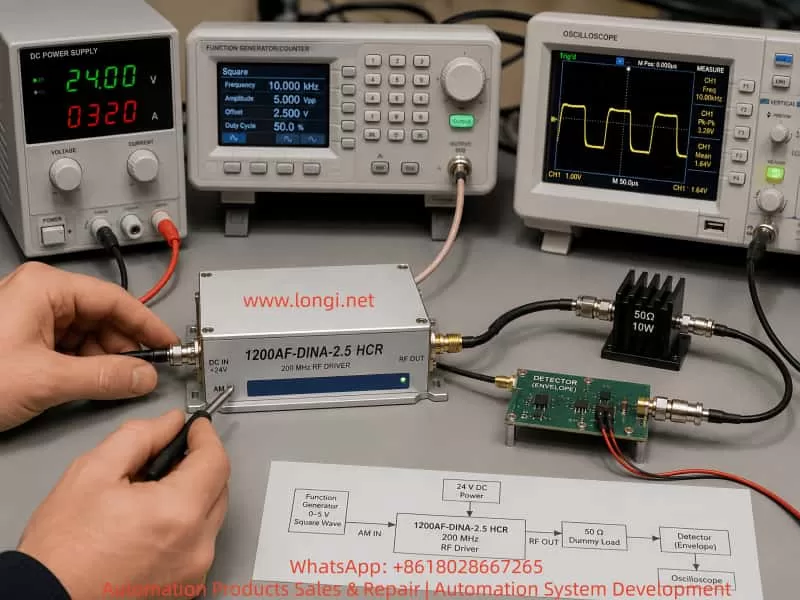
Without a spectrum analyzer, RF power meter, 50 Ω oscilloscope input, or calibrated RF attenuator, the safest practical method is to use a simple detector circuit.
The detector converts the 200 MHz RF signal into a DC or low-frequency envelope signal that can be measured safely by a normal multimeter or oscilloscope.
8. Principle of a Simple RF Detector
The purpose of a simple RF detector is not to accurately measure the exact RF output power. Its purpose is to determine whether RF output exists and whether the RF output follows the AM IN control signal.
The detector is used to answer the following questions:
Is RF output present?
Does RF output decrease when AM IN is low?
Does RF output increase when AM IN is high?
Does RF output follow square-wave modulation?
A practical detector usually includes:
Coupling capacitor
Schottky diode
Load resistor
Filter capacitor
A typical circuit is:
RF input
↓
100 pF to 1 nF coupling capacitor
↓
Schottky diode
↓
Detector output node
↓
10 kΩ resistor to ground
↓
10 nF to 100 nF capacitor to ground
Coupling capacitor
The coupling capacitor blocks DC and passes RF energy into the detector circuit.
A practical range is:
100 pF to 1 nF
This range is generally suitable for RF around 200 MHz.
Schottky diode
The diode is the main RF detection component.
Recommended types include:
1N5711
BAT54
HSMS-2850
HSMS-2820
Schottky diodes are preferred because they have lower forward voltage and faster switching behavior than ordinary rectifier diodes.
A standard diode such as 1N4007 is not suitable for this application.
A 1N4148 may sometimes detect RF under strong-signal conditions, but it is usually less suitable than a proper Schottky diode for low-power RF detection around 200 MHz.
Load resistor
A 10 kΩ resistor provides a discharge path and establishes the detector load condition.
Filter capacitor
A capacitor in the range of 10 nF to 100 nF removes much of the RF carrier and produces a smoother DC or low-frequency envelope output.
9. Practical Detector Wiring Method
The recommended method is to use an SMA T-adapter or RF tee.
The RF output connection should be:
RF OUTPUT
↓
SMA T-adapter
├── Branch 1: 50 Ω or temporary 75 Ω RF load
└── Branch 2: simple RF detector input
The important principle is:
The RF dummy load must remain connected.
The detector is only a parallel sampling branch.
The detector must not replace the RF load.
The detector wiring is:
RF center pin
↓
Coupling capacitor
↓
Schottky diode anode
↓
Schottky diode cathode
↓
Detector output node
At the detector output node, connect:
10 kΩ resistor to RF ground
10 nF to 100 nF capacitor to RF ground
Measurement instruments should connect as follows:
Multimeter red lead → detector output node
Multimeter black lead → RF ground

Oscilloscope probe tip → detector output node
Oscilloscope ground clip → RF ground
RF ground is generally:
SMA outer shell
RF driver metal chassis
24 V supply negative terminal
Function generator ground
Oscilloscope ground
All test equipment should share a common reference ground.
10. Correct Function Generator Settings for AM IN
One of the most common errors in this type of test is misunderstanding the function generator amplitude setting.
For example, many function generators display:
Amplitude: 5 V
Offset: 0 V
But this may actually mean:
5 Vpp
Meaning the waveform swings from -2.5 V to +2.5 V
That output is not suitable for AM IN if the input is designed for 0 V to +5 V logic.
The intended AM IN test waveform should be:
Low level: 0 V
High level: +5 V
If the generator is configured in Vpp mode, the correct setting is normally:
Amplitude: 5 Vpp
Offset: +2.5 V
This creates:
0 V to +5 V
Before connecting the function generator to AM IN, the generator output should first be checked directly with the oscilloscope.
Use:
DC coupling
Appropriate voltage scale
Confirm minimum voltage is near 0 V
Confirm maximum voltage is near +5 V
Confirm there is no negative voltage excursion
Only after confirming the waveform should the function generator be connected to AM IN.
11. Step-by-Step AM IN Functional Verification Procedure
Step 1: Verify DC supply polarity
Confirm the RF driver supply connection:
Vcc+ → +24 VDC
Vcc- → 0 V / GND
Do not apply 24 V to AM IN.
Because the internal RF power amplifier may have significant quiescent current, the current limit should not be set too low.
A practical initial setting is:
24 VDC
Current limit: approximately 0.8 A
Observe whether the driver immediately enters current limit.
Step 2: Connect the RF load
RF OUTPUT must be connected to:
Preferred: 50 Ω dummy load, rated at 5 W or higher
Temporary: 75 Ω resistor load, rated at 5 W or higher
The load must be connected:
RF center pin ↔ RF shell / RF ground
Step 3: AM IN low-level test
Connect AM IN center pin to 0 V.
Observe:
Detector output should be low.
Supply current should remain stable.
RF amplifier temperature should remain controlled.
Step 4: AM IN high-level test
Apply +5 V to the AM IN center pin.
Observe:
Detector output should rise significantly.
Supply current may change slightly.
RF amplifier temperature may increase moderately.
The exact detector voltage is not the critical measurement. The key is a clear, repeatable difference between AM IN low and AM IN high.
For example:
AM IN = 0 V
Detector output = 0.05 V

AM IN = +5 V
Detector output = 1.2 V

AM IN returned to 0 V
Detector output returns near 0.05 V
This indicates that:
The AM IN input stage is working.
The RF enable chain is responding.
The RF power path is being controlled.
RF output activity changes with the command signal.
Step 5: Square-wave modulation test
Set the function generator to:
Waveform: square wave
Frequency: 1 kHz
Amplitude: 5 Vpp
Offset: +2.5 V
Duty cycle: 50%
Connect the oscilloscope to the detector output node.
Under normal conditions, the detector output should change at the same frequency as the function generator.
The waveform may not look like a perfect square wave because the detector circuit includes an RC filter. Rounded edges and charge/discharge slopes are normal.
A good result is:
Input = 1 kHz
Detector output switches at approximately 1 kHz

Input = 10 kHz
Detector output still follows

Input = 100 kHz
Detector output still shows synchronized modulation
If the oscilloscope displays an unrelated value such as 13 Hz or 20 Hz while the function generator is set to another frequency, the result is not valid. This may indicate incorrect triggering, poor grounding, RF pickup, incorrect probe location, or a detector wiring problem.
12. Why Random Oscilloscope Waveforms Do Not Prove a Successful Repair
During RF testing, it is common to place an oscilloscope probe near the RF output or detector circuit and observe noisy, high-frequency, irregular waveforms.
Such waveforms may come from:
- RF radiation from the output cable;
- RF leakage from the amplifier module;
- Ground-loop noise;
- Probe ground lead acting as an antenna;
- Reflections caused by a 75 Ω temporary load;
- Improper detector wiring;
- Incorrect scope trigger configuration;
- Incorrect probe placement;
- Function generator and RF driver not sharing common ground;
- RF amplifier instability;
- Switching power supply noise;
- Oscilloscope AC coupling or unsuitable timebase settings.
Therefore, simply seeing “some waveform” does not prove that AM IN has been repaired.
A valid functional test requires the following relationship:
AM IN = 0 V → detector output low
AM IN = +5 V → detector output high
AM IN toggled high/low → detector output toggles correspondingly
Square-wave AM IN → detector output follows the same modulation frequency
This relationship is much more important than the exact waveform shape.
13. Common Wiring Errors and Their Consequences
Error 1: Applying 24 V directly to AM IN
Possible consequences:
Input protection resistor burns
Clamp diode fails
Logic IC input is damaged
RF enable function is lost
RF output remains permanently ON or OFF
Error 2: Leaving RF OUTPUT open-circuit
Possible consequences:
Reflected RF power increases
RF amplifier temperature rises
Output stage becomes unstable
RF amplifier damage risk increases
Error 3: Connecting a normal oscilloscope probe directly to RF OUTPUT
Possible consequences:
Severe impedance mismatch
Distorted measurement
Unstable RF operation
Possible probe or oscilloscope input damage
Error 4: Connecting the dummy load using long wires
Possible consequences:
Additional inductance
Impedance distortion
Antenna-like radiation
Unstable or misleading results
Error 5: Applying a waveform with negative voltage to AM IN
Possible consequences:
Input protection may be damaged again
Logic input may operate incorrectly
RF enable may become unstable
Error 6: Failing to establish common ground
Possible consequences:
AM IN reference level becomes undefined
Oscilloscope waveform becomes unstable
Control signal may not be recognized
RF noise and interference increase
14. Practical Final Acceptance Criteria
Without a spectrum analyzer or RF power meter, it is not possible to fully verify exact output frequency, absolute RF power, harmonic content, spurious emission, and calibrated modulation depth.
However, a technician can still perform a reliable functional acceptance test.
The following points should be confirmed:
1. The driver receives correct 24 VDC supply.
2. There is no reverse polarity or abnormal current limiting.
3. The RF power module temperature rise is controlled.
4. RF OUTPUT is connected to a proper 50 Ω load, or temporary 75 Ω load for short tests.
5. AM IN at 0 V produces low detector output.
6. AM IN at +5 V produces clearly higher detector output.
7. Repeated AM IN high/low switching produces repeatable detector response.
8. A 1 kHz square-wave AM IN signal produces a corresponding detector waveform.
9. Higher modulation frequencies such as 10 kHz and 100 kHz can still be followed.
10. The unit remains stable during several minutes of operation.
11. No abnormal current surge, overheating, oscillation, or random RF dropout occurs.
If these conditions are met, the technician can reasonably conclude:
The AM IN repair is functionally successful.
The input control stage is working.
The RF switching or enable path is responding.
The RF output path is active.
The driver can proceed to final verification with proper RF instruments.
However, final customer delivery should ideally include testing with:
A calibrated 50 Ω RF dummy load
An RF power meter
A spectrum analyzer
A directional coupler
A simple detector circuit proves that RF output exists and responds to AM IN control. It does not guarantee:
Exact output frequency is correct
Output power is exactly 2.5 W
Harmonics are within specification
Spurious output is within specification
RF matching performance is fully compliant
15. Conclusion
RF drivers used in AOM and optical systems may appear simple externally, with only a DC supply input, an AM IN control port, and an RF OUTPUT connector. Internally, however, they contain high-speed logic, RF switching, oscillator circuits, power amplifiers, impedance-matching networks, and thermal management structures.
When AM IN is incorrectly connected to 24 VDC, the damage may extend beyond a visible resistor or protection diode. A successful repair must confirm that the logic input, RF-enable chain, and RF output response all function correctly.
The correct verification method is not merely “the unit powers on” or “the oscilloscope shows some waveform.” The correct logic is:
Correct DC supply
→ Proper RF termination
→ Correct AM IN voltage level
→ Proper RF detector connection
→ Low-level and high-level comparison
→ Square-wave synchronization test
When AM IN at 0 V produces a low detector reading, AM IN at +5 V produces a substantially higher detector reading, and a square-wave input produces synchronized detector switching, the repair can be considered functionally successful.
For RF equipment, correct load matching, short wiring, common grounding, thermal control, and suitable measurement methods are as important as component-level repair. Avoiding future 24 V misconnection, avoiding open-circuit RF output, and avoiding direct probing of high-frequency RF output will significantly improve reliability and prevent repeat failure.