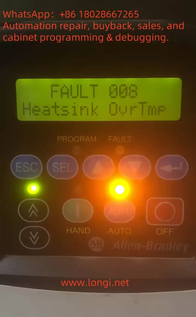
A Systematic Troubleshooting Guide for CSD3-10BX2 Servo Drives Showing an E-Series Fault Code
Servo drive alarms are often misdiagnosed because technicians focus only on the code displayed on the front panel. In many cases, the displayed code is only the final result of an abnormal condition detected by the drive. It does not always identify the actual failed component.
This is especially true for older servo systems such as the Allen-Bradley OEMax CSD3 Plus series. These drives are commonly installed in packaging machines, textile machinery, assembly systems, CNC auxiliary axes, conveyors, and other equipment requiring precise motor positioning and speed control.
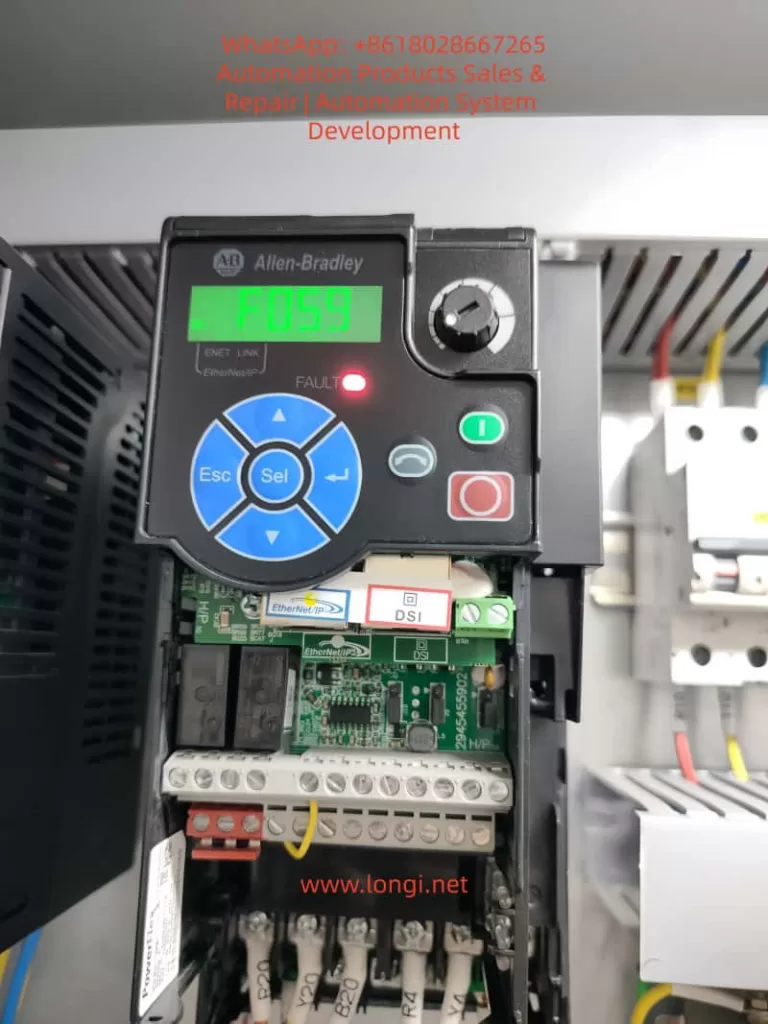
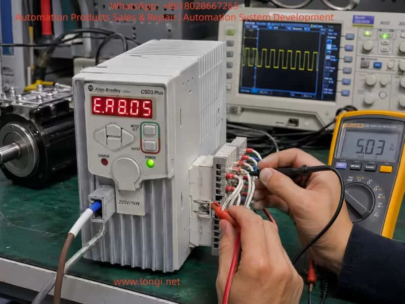
The drive shown in the example is an Allen-Bradley OEMax CSD3 Plus servo drive, model CSD3-10BX2. According to the nameplate, it is a 200–240 Vac three-phase servo drive with an output capacity of approximately 1.0 kW. The drive is manufactured on the RS Automation CSD3 servo platform and uses closed-loop motor feedback, typically through an encoder system.
When this type of drive displays an E-series fault code immediately after power-up, technicians should not immediately conclude that the IGBT module, motor, or encoder is defective. A structured diagnosis is required because the same alarm category may be triggered by encoder feedback failure, low-voltage power supply problems, parameter corruption, internal communication faults, power-stage protection signals, or external enable-chain issues.
This article explains how to diagnose and repair CSD3 Plus servo drive alarms in a systematic way, with particular attention to drives that display an E-type fault code during startup.
1. Identifying the Servo Drive
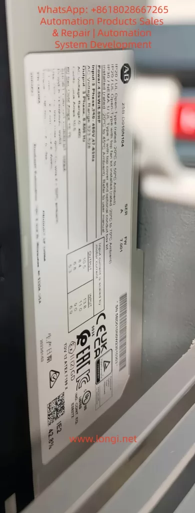
The unit discussed here is identified as:
- Brand: Allen-Bradley OEMax
- Series: CSD3 Plus Servo Drive
- Model: CSD3-10BX2
- Input voltage: 200–240 Vac, three-phase, 50/60 Hz
- Input current: approximately 11 A
- Output voltage: 0–240 Vac, three-phase
- Output capacity: approximately 1.0 kW
- Output current: approximately 7.6 A
- Manufacturer platform: RS Automation
- Country of manufacture: Korea
This is not a standard variable-frequency drive. Although it has three-phase motor output terminals, it is a closed-loop servo drive. Its operation depends on continuous feedback from the motor encoder.
A normal VFD can control a standard induction motor mainly by generating a variable frequency and voltage. A servo drive must also monitor motor position, speed, direction, acceleration, deceleration, torque demand, and feedback integrity. For this reason, servo drives are much more sensitive to encoder faults, parameter mismatches, power-supply instability, and communication errors.
2. Why an E-Series Alarm Requires Careful Diagnosis
In many servo systems, an E-series display indicates that the drive has detected an abnormal condition during initialization, standby, servo-enable operation, or motor control.
The fault may be related to one of the following areas:
- Encoder communication failure
- Encoder power-supply failure
- Motor identification mismatch
- Incorrect servo parameters
- Internal CPU self-test failure
- EEPROM or parameter memory failure
- Control board to power board communication fault
- DC bus voltage detection failure
- Current feedback circuit fault
- IGBT gate-driver protection signal
- External Servo ON input problem
- Emergency stop circuit open
- Positive or negative travel-limit signal active
- Internal low-voltage power-supply instability
Therefore, the displayed fault code should be treated as a starting point for diagnosis, not as a final conclusion.
A repair technician should first determine when the alarm occurs:
- Immediately after control power is applied
- After main power is applied
- Only after Servo ON is activated
- When the motor starts moving
- During acceleration
- During high-speed operation
- During deceleration
- Randomly after the machine has been running for some time
The timing of the alarm is one of the most useful clues in servo-drive troubleshooting.
3. The Importance of Startup Sequence
A servo drive performs several internal checks before it is ready to operate. During startup, the drive may verify the following conditions:
- Control power supply voltage
- Internal 5 V, 12 V, 15 V, and logic power rails
- CPU operation and reset status
- EEPROM or parameter memory integrity
- Encoder interface condition
- Motor feedback communication
- DC bus voltage level
- Pre-charge circuit condition
- Current sensor zero point
- Power-stage communication
- IGBT or IPM protection feedback
- Servo-enable input status
- Emergency stop circuit status
- Positive and negative travel limits
- Internal temperature or thermal-protection status
If any of these checks fails, the drive may refuse to enter Ready status and display an alarm.
For this reason, a drive that alarms immediately after power-up should not automatically be classified as a power-stage failure. In many cases, the fault is located in the encoder feedback circuit, the low-voltage power supply, or the control board.
4. The Most Common Causes of CSD3 Plus Startup Alarms
4.1 Encoder Feedback Failure
Encoder-related problems are among the most common causes of servo-drive alarms.
The servo drive needs feedback information from the motor encoder to establish a closed control loop. If the encoder signal is absent, unstable, corrupted, or incompatible, the drive may generate an E-series error before the motor is allowed to run.
Common causes include:
- Loose encoder connector
- Bent or oxidized connector pins
- Broken encoder cable inside a cable carrier
- Oil contamination inside the connector
- Coolant ingress into the motor connector
- Damaged cable shielding
- Incorrect cable wiring
- Encoder power supply missing
- Encoder internal circuit failure
- Motor encoder damaged after collision or vibration
- Encoder cable routed together with motor power cables
- Poor grounding causing electrical interference
- Incorrect replacement motor or encoder type
In many industrial machines, the encoder cable is repeatedly bent inside a drag chain. The cable may look normal from outside while one or more internal conductors are broken. This is especially common near the motor connection, near the machine frame, or at the fixed end of the cable carrier.
A damaged encoder cable can create intermittent faults. The machine may work normally when stationary but alarm during motion, vibration, or axis travel.
4.2 Encoder Power Supply Failure
The encoder itself may be healthy while the drive is unable to provide correct power to it.
The encoder interface usually receives a regulated low-voltage supply from the servo drive. Depending on the design, this may include 5 V, 12 V, or other low-voltage rails.
The following checks are important:
- Is the encoder supply voltage present?
- Is the supply stable after power-up?
- Does the voltage collapse when the encoder cable is connected?
- Is there excessive ripple on the encoder supply?
- Does the power supply remain stable during Servo ON?
- Is the encoder interface voltage affected by cable movement?
If the drive produces a stable 5 V supply with the encoder unplugged, but the voltage falls sharply when the encoder is connected, the likely causes are:
- Short circuit inside encoder cable
- Short circuit inside motor encoder
- Moisture in the encoder connector
- Failed TVS protection diode on the drive interface
- Shorted filter capacitor
- Damaged encoder interface IC
- Damaged shielding or grounding connection
Repeatedly powering the drive under a shorted encoder condition may damage the internal low-voltage regulator. Therefore, excessive repeated testing should be avoided.
4.3 Parameter Corruption or Motor Mismatch
Servo drives are not universal devices. The drive parameters must match the connected servo motor and encoder.
If the drive has been repaired, reset, replaced, or incorrectly configured, it may not recognize the motor correctly.
Typical causes include:
- Factory reset performed without parameter backup
- Incorrect motor model selected
- Incorrect encoder type configured
- Wrong motor capacity parameter
- Wrong control mode selected
- Incorrect electronic gear ratio
- Incorrect encoder resolution setting
- Absolute encoder mode set incorrectly
- Parameter memory corruption
- Replacement drive installed without transferring original settings
A parameter mismatch may cause the drive to alarm immediately, or it may allow Servo ON but alarm when motion begins.
It is important not to reset the drive to factory defaults without recording the original parameters. On older machines, the original parameter list may no longer be available. A full reset can cause new problems such as incorrect direction, excessive gain, overtravel, homing failure, or machine collision.
4.4 External Servo ON, Emergency Stop, or Limit Circuit Problems
A servo drive often depends on external digital inputs before it can enter normal operating condition.
These may include:
- Servo ON
- Alarm reset
- Emergency stop
- Safety relay output
- Positive travel limit
- Negative travel limit
- External interlock
- Brake release signal
- PLC enable command
- Controller readiness signal
If any of these signals is missing or in the wrong logic state, the drive may not enable correctly.
Typical external causes include:
- Failed PLC output
- 24 V control power missing
- Burned relay contact
- Loose terminal screw
- Emergency stop button activated
- Door safety switch open
- Broken limit switch cable
- Incorrect NPN/PNP wiring
- Incorrect common terminal connection
- Improper input polarity
- External safety circuit not reset
Before opening the servo drive, it is important to verify the external control wiring. A normal drive can be incorrectly diagnosed as defective if the safety chain is open.
5. Why the IGBT Module Should Not Be the First Suspect
When a servo drive shows an alarm, many technicians immediately inspect the IGBT module. This is understandable because IGBTs are critical components in the output stage. However, they are not always the most likely cause of a startup alarm.
A failed IGBT module often produces more obvious symptoms, such as:
- Input breaker trips immediately
- Main fuse is blown
- DC bus is shorted
- P-to-N resistance is abnormally low
- U, V, or W output is shorted to DC bus
- Drive alarms immediately after Servo ON
- Motor vibrates sharply and faults
- Severe overcurrent alarm
- Burn marks on the power board
- Abnormal heating
- Failed pre-charge circuit
- Brake transistor short circuit
If the control power LED is on and the drive displays an alarm without tripping the breaker, the first inspection should usually focus on low-voltage supplies, encoder circuits, control board signals, and external control inputs.
This does not mean that the power stage is definitely good. A power-stage fault can also occur without a hard short circuit. For example:
- IGBT gate-driver voltage may be missing
- Current sensor output may be incorrect
- IPM fault output may be permanently active
- Power board communication may be lost
- Brake circuit feedback may be abnormal
- One phase may have a gate-drive problem
- DC bus voltage sensing may be incorrect
However, these conditions require deeper testing than a simple resistance check of U, V, and W terminals.
6. External Inspection Before Removing the Drive
Before sending the drive for repair or opening the unit, perform a complete external inspection.
6.1 Record the Fault Condition
Document the following information:
- Full servo drive model number
- Serial number
- Exact displayed fault code
- Whether the code is steady or flashing
- Whether the alarm appears immediately after power-up
- Whether the motor moves before the alarm
- Whether the fault occurs only after Servo ON
- Whether the fault occurs only during motion
- Recent machine events before the fault
- Previous repairs or replacement parts
- Whether the machine had a collision
- Whether the machine was exposed to water, oil, lightning, power loss, or voltage instability
This information is extremely valuable during bench repair.
6.2 Inspect Motor and Encoder Connections
Check the following carefully:
- Encoder connector fully locked
- Motor power connector secure
- Connector pins not bent or oxidized
- No coolant, oil, or water inside connectors
- Cable shielding intact
- Cable jacket not damaged
- No sharp bending near connectors
- Encoder cable separated from U/V/W motor cables
- No cable crushed inside machine frame
- No drag-chain damage
- Motor brake wiring intact
- Proper ground connection present
The encoder cable should not be routed together with motor output cables for long distances. The high-frequency switching noise from the servo output can interfere with weak feedback signals.
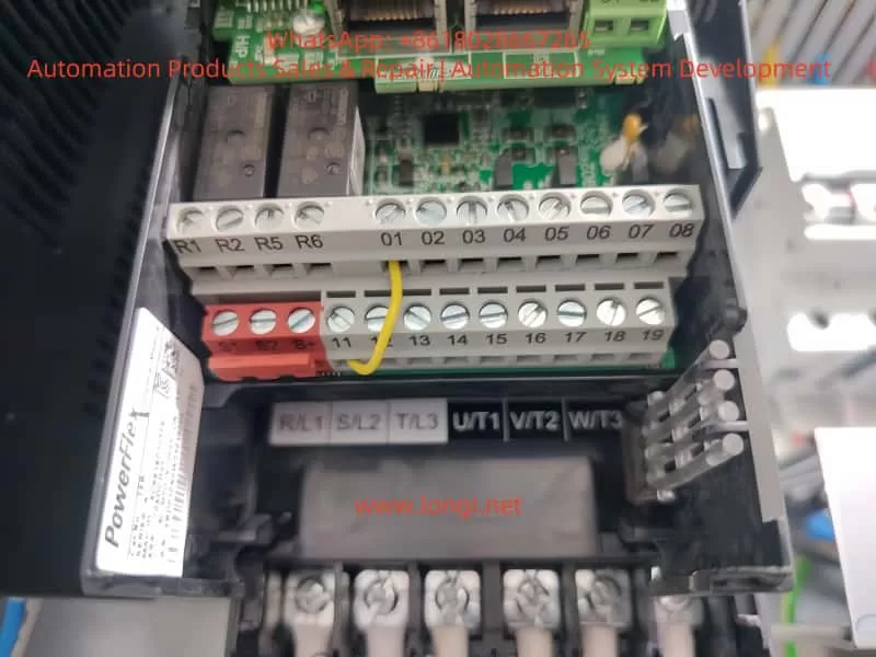
6.3 Verify Input Power
The CSD3-10BX2 is intended for 200–240 Vac three-phase input.
Measure:
- R-S voltage
- S-T voltage
- R-T voltage
- Voltage balance between phases
- Voltage drop during startup
- Main contactor condition
- Fuse condition
- Terminal tightness
- Transformer output voltage, if applicable
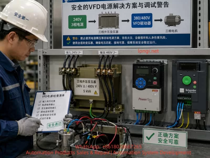
A serious mistake is applying 380 Vac three-phase power to a 220 Vac servo drive. This can cause immediate and extensive damage to the rectifier stage, DC bus capacitors, low-voltage power supply, power module, and control board.
Always confirm actual voltage with a meter. Do not rely only on cabinet labels.
7. Internal Repair Procedure for a Drive That Alarms with Minimal External Wiring
If the drive continues to display the same alarm after external wiring, motor, and encoder issues have been excluded, internal diagnosis is required.
A proper repair sequence should proceed from high-energy power circuits toward low-voltage logic circuits.
7.1 Check Rectifier and DC Bus Circuit
After disconnecting power and allowing sufficient time for the DC bus capacitors to discharge, inspect:
- Three-phase rectifier bridge
- DC bus terminals P and N
- Main filter capacitors
- Pre-charge resistor
- Pre-charge relay
- Brake transistor
- Brake resistor terminals
- DC bus voltage sensing circuit
- Bus capacitor ESR and leakage
- Burnt resistors or damaged tracks
If P and N are directly shorted, isolate the possible fault sections one by one:
- IGBT or IPM module
- Brake transistor
- DC bus capacitors
- Rectifier bridge
- Snubber circuit
- Power board contamination
A direct bus short should never be ignored. Do not repeatedly apply power to a drive with a suspected DC bus short.
7.2 Check IGBT or IPM Module
The power module should be tested carefully.
Measure:
- P to U, V, W
- N to U, V, W
- U to V
- V to W
- U to W
- Gate-driver pins if accessible
- Fault feedback output
- Driver supply voltage
- Isolation between power stage and control stage
A simple diode-test reading is useful, but it is not enough to prove that the IGBT stage is healthy.
The power stage may still fail because of:
- Missing gate-drive voltage
- Failed gate resistor
- Failed optocoupler
- Faulty driver IC
- Current sensor offset
- Internal protection latch
- One phase not switching correctly
- Power board connector oxidation
- Cracked solder joints
- Temperature sensor fault
For this reason, an oscilloscope is often required to verify gate signals and driver supply rails.
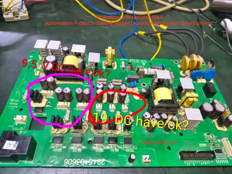
7.3 Check Low-Voltage Power Supplies
Low-voltage power supply failure is very common in older servo drives.
The following rails should be checked:
- +5 V
- +3.3 V
- +12 V
- +15 V
- -15 V, where applicable
- Isolated driver supply rails
- Encoder supply voltage
- CPU supply voltage
- Reference voltage circuits
Typical failures include:
- Aged electrolytic capacitors
- High ESR capacitors
- Failed switching controller IC
- Failed optocoupler
- TL431 reference circuit failure
- Shorted secondary diode
- Failed DC/DC converter
- Cracked solder joint
- Damaged regulator IC
- Open SMD fuse
- Burnt startup resistor
If the supply voltage is low or unstable, the CPU may reset repeatedly, the encoder interface may malfunction, and the drive may display an internal alarm even though the main power stage is not defective.
7.4 Check Encoder Interface Circuit
The encoder interface should be treated as a priority area.
Inspect and test:
- Encoder connector solder joints
- Connector pin condition
- 5 V supply fuse or resettable fuse
- TVS protection diodes
- Common-mode choke components
- Data-line protection arrays
- Differential receivers
- Differential transmitters
- Optocouplers, if used
- Interface IC supply voltage
- Filter capacitors
- Grounding and shield connection
A failed TVS diode can short the encoder supply line to ground. A damaged receiver IC can prevent encoder communication even when the encoder itself is good. A cracked connector solder joint can create intermittent feedback loss.
In environments with oil mist, coolant, vibration, or frequent cable movement, encoder-interface failures are common.
7.5 Check Control Board and Parameter Memory
If the power section, low-voltage supplies, and encoder interface appear normal, inspect the control board.
Important areas include:
- Main MCU or DSP
- Crystal oscillator
- Reset circuit
- EEPROM or Flash memory
- CPU supply rail
- Watchdog circuit
- Board-to-board communication
- Power board communication connector
- Corrosion around IC pins
- Solder cracks under large components
- Parameter memory integrity
- Communication transceivers
Faults in this area may require comparison with a known-good drive, oscilloscope testing, logic analysis, and EEPROM programming tools.
If a replacement control board is installed, parameter compatibility must be confirmed before attempting operation.
8. Isolation Testing: Internal Fault or External Fault?
A useful method is to separate the problem into two categories:
- Fault caused by the drive itself
- Fault caused by external motor, cable, encoder, PLC, or safety circuit
Scenario A: The Drive Alarms with External Wiring Removed
If the drive still alarms with the following disconnected:
- Motor power cable
- Encoder cable
- PLC control wiring
- Communication cable
- External I/O
- Servo ON signal
- Brake wiring
then the fault is more likely inside the drive.
Possible internal causes include:
- Low-voltage power supply failure
- Control board failure
- Parameter memory problem
- Encoder interface fault
- Power board communication fault
- DC bus sensing failure
- Current-sensor fault
- Gate-driver protection fault
- Internal CPU self-test failure
However, note that some servo drives are designed to alarm if no encoder is connected. Therefore, this test should ideally be compared with a known-good drive of the same model.
Scenario B: The Drive Is Normal Without the Motor but Alarms When the Motor Is Connected
This condition strongly suggests an external problem.
Priority suspects include:
- Encoder cable
- Motor encoder
- Motor power cable
- Motor winding fault
- Brake coil fault
- Incorrect motor
- Incorrect encoder type
- Cable shielding issue
- Incorrect wiring sequence
- Connector contamination
- Motor-to-ground insulation failure
The best way to confirm this is through substitution testing:
- Test with a known-good motor.
- Test with a known-good encoder cable.
- Test the motor on another compatible drive.
- Test the drive with another compatible motor.
- Measure encoder supply voltage with and without the cable connected.
- Check motor winding resistance and insulation resistance.
Substitution testing is often more reliable than simple resistance measurements.
9. Common Misdiagnoses During Servo Drive Repair
Misdiagnosis 1: Every E-Series Fault Is an Encoder Fault
Encoder faults are common, but they are not the only cause.
An E-series fault may also result from:
- CPU self-test failure
- EEPROM corruption
- Internal communication failure
- Current feedback circuit problem
- DC bus sensing error
- Power board protection signal
- Low-voltage supply instability
- Parameter mismatch
- External enable-chain issue
Replacing the encoder without testing the encoder supply and interface circuit may waste time and money.
Misdiagnosis 2: No U/V/W Short Means the Power Stage Is Good
A power module may pass a basic diode test and still be defective.
Possible hidden failures include:
- Gate drive missing on one phase
- Current feedback abnormal
- IGBT protection feedback stuck active
- Driver supply voltage missing
- Brake circuit malfunction
- Power-stage communication fault
- Thermal sensor fault
- Cracked solder joint
- Output waveform distortion
A proper diagnosis requires more than checking terminal resistance.
Misdiagnosis 3: Resetting Parameters Immediately
Factory reset should not be the first action.
Resetting the drive can erase machine-specific settings such as:
- Motor model
- Encoder type
- Electronic gear ratio
- Position command mode
- Speed loop gain
- Position loop gain
- Acceleration and deceleration parameters
- Homing settings
- Input logic
- Output logic
- Torque limit
- Travel-limit configuration
On an older machine, these parameters may be impossible to recover. A parameter reset can turn a repairable fault into a commissioning problem.
Misdiagnosis 4: Ignoring Cable and Connector Problems
A servo drive may test normal on the repair bench but fail again after installation.
Common reasons include:
- Broken wire inside drag chain
- Intermittent encoder cable
- Loose motor connector
- Contaminated encoder plug
- Poor grounding
- External electrical noise
- Damaged PLC output
- Unstable 24 V supply
- Poor cabinet wiring
- Loose terminal screw
A proper repair should include dynamic testing with a compatible motor and encoder whenever possible.
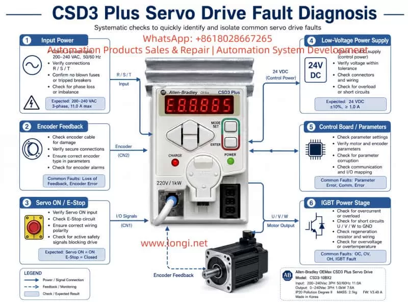
10. Recommended Standard Diagnostic Workflow
For a CSD3-10BX2 or similar CSD3 Plus servo drive, the following workflow is recommended.
Step 1: Record the complete model number and fault condition
Document the exact display, fault timing, and machine behavior.
Step 2: Verify the input voltage
Confirm that the drive receives 200–240 Vac three-phase input and is not connected to 380 Vac.
Step 3: Inspect motor, encoder, brake, and control wiring
Check connectors, cable condition, shield, grounding, and drag-chain movement.
Step 4: Check encoder power supply
Measure encoder supply voltage and observe whether it collapses when the encoder is connected.
Step 5: Check Servo ON and external safety inputs
Confirm 24 V control power, emergency stop loop, limit switches, PLC output, and enable logic.
Step 6: Reduce the system to minimum wiring
Disconnect unnecessary external signals and observe the drive behavior under controlled conditions.
Step 7: Inspect the DC bus and power circuit
Check rectifier bridge, pre-charge circuit, DC bus capacitors, brake transistor, and IGBT/IPM module.
Step 8: Inspect low-voltage power rails
Check 5 V, 12 V, 15 V, negative rails, and isolated driver supplies.
Step 9: Inspect encoder interface circuit
Test protection components, interface ICs, connector solder joints, and encoder supply circuitry.
Step 10: Inspect control board and parameter memory
Check MCU, oscillator, reset circuit, EEPROM, communication signals, and board-to-board connectors.
Step 11: Perform motor matching and no-load testing
Use a compatible motor and encoder to test Servo ON, direction, low-speed rotation, and alarm response.
Step 12: Perform dynamic and thermal testing
Run repeated start-stop tests, acceleration tests, low-speed and high-speed tests, and temperature monitoring.
11. Conclusion
Allen-Bradley CSD3 Plus servo drives such as the CSD3-10BX2 should not be diagnosed only by the front-panel alarm code.
When an E-series fault appears, especially immediately after power-up, the most important areas to investigate are:
- Encoder feedback system
- Encoder power supply
- Motor and cable condition
- External Servo ON and safety circuit
- Low-voltage power supplies
- Control board self-test
- Parameter memory
- Power board communication
- DC bus voltage detection
- Current feedback and gate-driver protection circuits
In many cases, the actual failure is not the IGBT module. More common causes include broken encoder cables, damaged connectors, failed 5 V encoder supply circuits, aged low-voltage capacitors, parameter mismatch, internal interface faults, and unstable control power.
A reliable repair process should follow a complete diagnostic chain:
Fault display → external wiring → encoder feedback → control power → low-voltage rails → power stage → control board → dynamic motor test.
This method reduces unnecessary component replacement, improves repair accuracy, and provides a much higher chance that the servo drive will remain stable after it is returned to service.