Posted on

Systematic Diagnosis and Troubleshooting of Inovance MD310 Err10 Faults

A Technical Case Study of a 7.5 kW Variable-Frequency Drive and Three-Phase Induction Motor

Introduction

Variable-frequency drives are widely used in fans, pumps, conveyors, mixers, machine tools, packaging machinery, and many other industrial systems. Their main functions include motor speed control, soft starting, torque regulation, energy saving, and electrical protection.

When a drive displays a fault code, the correct response is not to replace the drive immediately, repeatedly reset the fault, or disable the protection function. A reliable diagnosis must consider the fault code, motor nameplate data, drive capacity, operating current, load characteristics, parameter settings, wiring condition, and the exact stage at which the fault occurs.

This article analyzes an actual case involving an Inovance MD310T7.5B variable-frequency drive operating a 7.5 kW three-phase induction motor. The drive displayed the fault code Err10.

The main equipment data are as follows:

  • Drive model: Inovance MD310T7.5B
  • Rated drive power: 7.5 kW
  • Drive input: Three-phase AC 380–440 V
  • Rated drive output current: Approximately 17 A
  • Motor rated power: 7.5 kW
  • Motor rated voltage: 380 V
  • Motor rated current: 15 A
  • Motor rated frequency: 50 Hz
  • Motor rated speed: 1440 r/min
  • Drive fault code: Err10

Based on the rated power and current, the drive and motor are generally matched. Therefore, the fault should not be attributed immediately to insufficient drive capacity. The actual cause may be related to mechanical overload, motor stall, incorrect motor parameters, improper wiring, poor cooling, abnormal power supply, or a defect in the drive’s current-detection circuit.

The following sections present a complete diagnostic method that can also be applied to many other induction-motor systems.
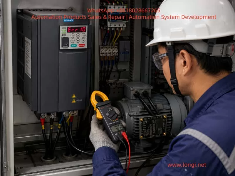

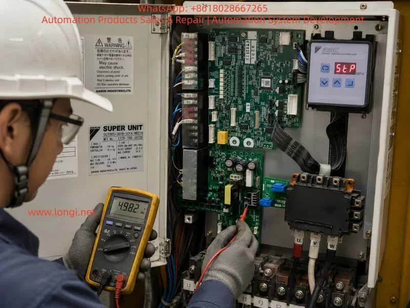
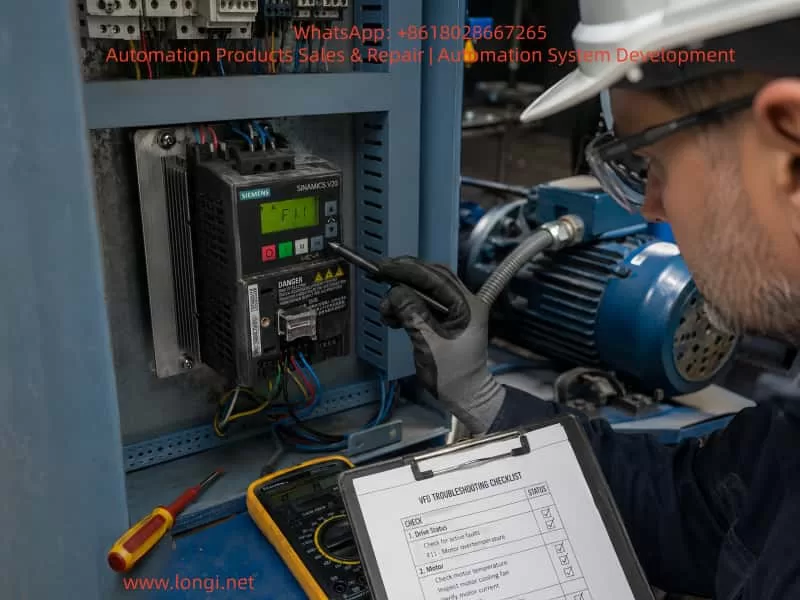
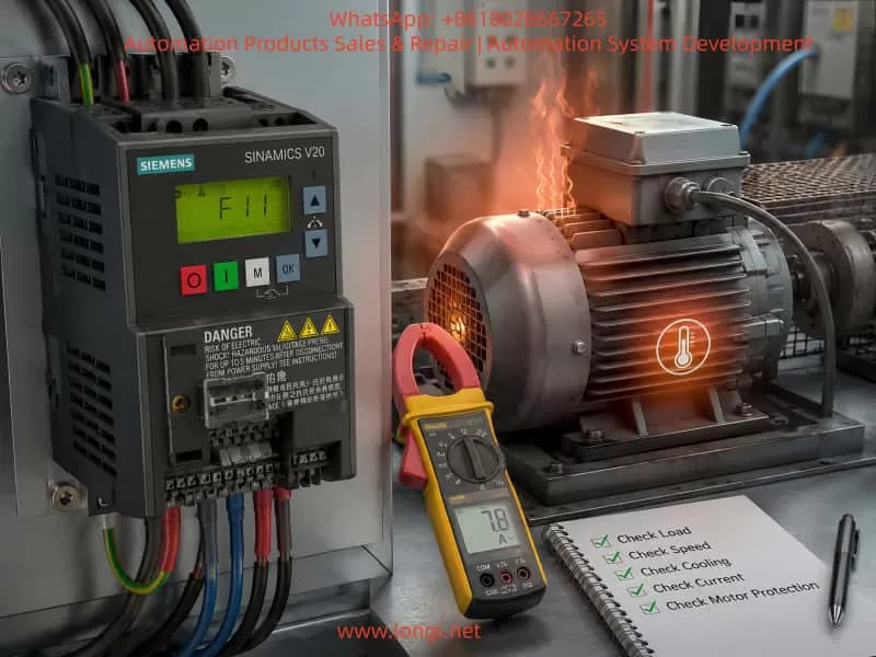
Industrial technician diagnosing an Inovance MD310 variable-frequency drive displaying Err10 while measuring the current of a 7.5 kW three-phase motor inside an electrical control cabinet.

1. Meaning of Err10 on an Inovance MD310 Drive

On the Inovance MD310 series, Err10 means drive overload.

Typical causes include:

  1. Excessive mechanical load
  2. Motor stall
  3. Undersized drive capacity

The corresponding corrective actions are generally:

  • Reduce the mechanical load
  • Inspect the motor and driven equipment
  • Use a drive with a larger capacity when necessary

A drive-overload fault is not exactly the same as an instantaneous overcurrent fault.

An overcurrent fault usually means that the output current has exceeded a hardware protection threshold within a very short period. A drive-overload fault normally indicates that the drive has carried excessive current for a certain duration, causing its internal thermal model or overload calculation to reach the protection limit.

For example, a brief current peak during acceleration may not trigger Err10. However, if the motor remains in a high-current condition for several seconds or minutes because of heavy load, slow acceleration, low-speed stalling, or mechanical blockage, the drive may eventually trip on overload.

Therefore, Err10 essentially means:

The drive has detected that its output current and overload duration have exceeded the permitted operating range.

This does not automatically mean that the drive is damaged. It means that the drive is protecting itself from prolonged electrical and thermal stress.
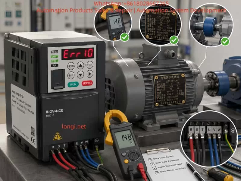

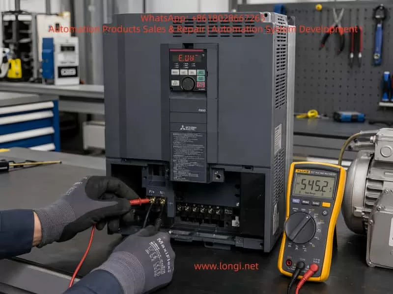
Technical troubleshooting illustration of an Inovance MD310 drive with an Err10 overload fault, showing a 7.5 kW motor, current measurement, motor parameter verification, mechanical load inspection, and wiring checks.

2. Why a 7.5 kW Drive Can Overload a 7.5 kW Motor

A common misunderstanding is that a 7.5 kW drive can always operate a 7.5 kW motor without overload. In practice, drive selection cannot be based on power alone.

The following factors must also be considered:

  • Motor rated current
  • Drive rated output current
  • Motor starting torque
  • Load torque characteristics
  • Acceleration time
  • Operating frequency
  • Duty cycle
  • Ambient temperature
  • Installation altitude
  • Frequency of starting and stopping
  • Frequency of forward and reverse operation
  • Mechanical inertia
  • Shock-load conditions

In this case, the motor rated current is 15 A and the drive rated output current is approximately 17 A. The current margin is therefore only about 2 A.

If the motor normally operates at 15–16 A, even a relatively small increase in load may push the drive beyond its continuous current capability. This can happen because of:

  • Increased mechanical friction
  • Reduced supply voltage
  • Short acceleration time
  • Incorrect motor parameters
  • Partial brake engagement
  • Bearing deterioration
  • Product buildup in the machine
  • Improper motor connection

For constant-torque or impact-load applications, a drive with the same nominal power as the motor may not provide sufficient overload margin.

Applications that require particular attention include:

  • Mixers
  • Crushers
  • Extruders
  • Hoists
  • Fully loaded conveyors
  • Compressors
  • Centrifuges
  • Large-inertia rotating machinery
  • Machines with frequent reversing
  • Equipment that cannot start unloaded

Fans and centrifugal pumps usually have relatively favorable starting characteristics, but conveyors, mixers, hoists, and crushers may require considerably more starting torque.

Therefore, the correct selection principle is:

Compare both rated power and rated current, and evaluate the actual load profile rather than relying on the kW rating alone.


3. Difference Between Err10 and Err11

On the MD310 series:

  • Err10: Drive overload
  • Err11: Motor overload

The distinction is important.

Err10 protects the drive power section and its internal overload model. Err11 mainly protects the motor according to motor rated current and electronic thermal protection settings.

If a motor rated at 15 A is incorrectly configured as a 9 A motor, motor overload protection may operate too early. If the motor rated current is configured excessively high, the motor may not receive adequate protection and could overheat.

Therefore, technicians should confirm the exact fault code before starting diagnosis.

For Err10, the main concerns are:

  • Excessive drive output current
  • Mechanical overload
  • Motor stall
  • Insufficient drive capacity
  • Current-measurement error

For Err11, the main concerns are:

  • Motor electronic thermal protection
  • Motor rated current setting
  • Motor cooling
  • Motor overload duration

The two faults may be caused by similar field conditions, but their protection targets and parameter relationships are different.


4. Determine When the Fault Occurs

The timing of the Err10 fault is one of the most useful diagnostic clues.

Before changing any parameter, determine whether the fault occurs:

  • Immediately after power-up
  • Immediately after pressing RUN
  • During acceleration
  • After reaching the commanded frequency
  • After several minutes of operation
  • Only under load
  • Even under no-load conditions
  • Every time or only intermittently

The operator should also be asked whether there was:

  • Abnormal noise
  • Reduced speed
  • Vibration
  • Burning smell
  • Mechanical jamming
  • Product buildup
  • Recent motor replacement
  • Recent drive replacement
  • Recent parameter modification
  • Recent maintenance on the gearbox or driven machine

4.1 Err10 Appears Immediately After RUN

If the drive trips almost immediately after receiving the run command, the likely causes include:

  • Motor shaft locked
  • Mechanical equipment jammed
  • Electromagnetic brake not released
  • Motor wiring short circuit
  • Motor winding fault
  • Incorrect star/delta connection
  • Severe motor parameter error
  • Drive current-detection fault

If the motor does not rotate and the current rises rapidly, the system is probably in a stalled condition.

4.2 Err10 Appears During Acceleration

If the motor starts but trips while increasing speed, inspect:

  • Acceleration time
  • Load inertia
  • Starting load
  • Motor torque capability
  • Mechanical resistance
  • Brake release
  • Motor parameter identification
  • Control mode
  • V/f curve

A short acceleration time forces the motor to produce both load torque and acceleration torque. If the load inertia is high, the drive must supply excessive current for an extended period.

This is common in:

  • Conveyors
  • Centrifuges
  • Large fans
  • Mixers
  • High-inertia rollers
  • Heavy rotating tables

4.3 Err10 Appears After Several Minutes

If the machine starts and reaches full speed normally but trips after operating for several minutes, the likely causes are:

  • Continuous overload
  • Mechanical load gradually increasing
  • Bearing temperature increasing
  • Gearbox resistance increasing
  • Product accumulation
  • Drive cooling fan failure
  • Blocked ventilation
  • High cabinet temperature
  • Low supply voltage
  • Long-term operation close to the current limit

Although inadequate cooling may more commonly produce an overtemperature fault, poor cooling reduces the drive’s practical overload capability and can contribute to Err10.

4.4 Err10 Occurs Mainly at Low Frequency

Low-speed, high-torque operation is demanding for both the motor and the drive.

At low frequency:

  • The motor’s shaft-mounted cooling fan turns slowly
  • Motor cooling is reduced
  • High current may be required to produce torque
  • Incorrect motor parameters can cause weak torque
  • The drive may remain in current limiting
  • The motor may rotate slowly or stall

If the process requires continuous low-speed, high-torque operation, consider:

  • An inverter-duty motor
  • Forced external motor cooling
  • A larger motor
  • A larger drive
  • Closed-loop vector control
  • A mechanical reduction ratio change

5. Use the Fault History Data

The MD310 stores fault information and operating conditions at the time of the fault.

Useful parameters include:

  • F9-14: First previous fault type
  • F9-15: Second previous fault type
  • F9-16: Most recent fault type
  • F9-17: Output frequency at the most recent fault
  • F9-18: Output current at the most recent fault
  • F9-19: DC bus voltage at the most recent fault
  • F9-20: Input terminal status at the most recent fault

Among these, F9-18 is especially important.

5.1 Fault Current Clearly Above 17 A

If the recorded current is significantly higher than the drive rated current, the overload is probably real.

Check:

  • Mechanical blockage
  • Excessive load
  • Brake not released
  • Motor stall
  • Incorrect motor connection
  • Short acceleration time
  • High load inertia

5.2 Low Frequency and High Current

For example:

  • Fault frequency: 5 Hz
  • Fault current: 22 A
  • Motor speed: Very low or zero

This strongly indicates:

  • Motor stall
  • Mechanical jamming
  • Insufficient low-speed torque
  • Incorrect motor parameters
  • Brake engagement
  • Incorrect star/delta connection

5.3 Near-Rated Frequency and High Current

If the fault occurs at 40–50 Hz and the current remains high, the machine is probably running under excessive working load.

Typical causes include:

  • Conveyor overload
  • Pump blockage
  • High-viscosity material
  • Fan impeller friction
  • Tight belt
  • Damaged bearing
  • Gearbox problem
  • Excessive production rate

5.4 Recorded Current Is Low but Err10 Still Occurs

If the stored current is not high and Err10 occurs repeatedly, inspect the drive itself.

Possible causes include:

  • Current-sensor offset
  • Hall sensor drift
  • Current-sampling circuit fault
  • Operational amplifier fault
  • Control-board ADC error
  • Internal connector fault
  • Software or parameter corruption

Compare the drive display current with an external true-RMS clamp meter suitable for variable-frequency drive output.

If the drive displays 20 A while the external meter measures only 6 A, the current-detection circuit is likely inaccurate.


6. Check the Motor Nameplate Parameters

Accurate motor data are essential, especially in vector-control modes.

For this motor, the recommended basic values are:

ParameterDescriptionRecommended value
F1-00Motor typeStandard induction motor
F1-01Rated motor power7.5 kW
F1-02Rated motor voltage380 V
F1-03Rated motor current15.0 A
F1-04Rated motor frequency50.00 Hz
F1-05Rated motor speed1440 r/min

6.1 Effect of Incorrect Rated Current

If F1-03 is set too low:

  • Motor control may be inaccurate
  • Torque may be insufficient
  • Motor protection may operate too early
  • Low-speed performance may be poor

If F1-03 is set too high:

  • The motor may not be properly protected
  • The control model may be inaccurate
  • Motor temperature may rise excessively
  • A real overload may be hidden

The rated current must not be increased simply to suppress an alarm.

6.2 Effect of Incorrect Rated Speed

A 1440 r/min motor at 50 Hz is typically a four-pole induction motor.

A four-pole motor has a synchronous speed of 1500 r/min at 50 Hz. The lower rated speed is normal because induction motors require slip to produce torque.

If the motor rated speed is incorrectly entered as:

  • 960 r/min
  • 1500 r/min
  • 2900 r/min

The vector-control model may calculate slip and torque incorrectly.

6.3 Effect of Incorrect Rated Frequency

If a 50 Hz motor is configured as a 60 Hz motor, the voltage-to-frequency relationship may become incorrect.

This can cause:

  • Reduced magnetic flux
  • Insufficient torque
  • Overexcitation
  • Excessive current
  • Poor motor performance

Every nameplate parameter should therefore be checked individually.


7. Perform Motor Parameter Identification

Motor auto-tuning or parameter identification is important when using sensorless vector control.

The drive may identify or estimate:

  • Stator resistance
  • Rotor resistance
  • Leakage inductance
  • Mutual inductance
  • No-load current

7.1 Full Rotational Auto-Tuning

Where possible, disconnect the motor from the mechanical load.

Recommended procedure:

  1. Isolate the power supply.
  2. Disconnect the motor from the gearbox, belt, pump, or other driven equipment.
  3. Confirm that the motor shaft can rotate freely.
  4. Restore power.
  5. Select keypad control.
  6. Enter the correct motor nameplate parameters.
  7. Select full rotational identification.
  8. Press RUN.
  9. Keep personnel away from the motor.
  10. Wait until identification is completed.

During rotational identification, the motor may accelerate, decelerate, or change direction.

Safety precautions are essential:

  • The motor must be firmly mounted.
  • The shaft must not carry loose components.
  • The machine must be mechanically disconnected.
  • The brake must be released.
  • Personnel must stay clear.

7.2 Static Identification

If the motor cannot be disconnected from the machine, static identification can be used.

This may be suitable for:

  • Integrated pump units
  • Large machinery
  • Equipment where coupling removal is difficult
  • Applications where motor rotation is not permitted during tuning

Static identification is useful, but full rotational identification usually provides more accurate control data.

7.3 Do Not Auto-Tune Before Basic Electrical Checks

Do not perform auto-tuning if:

  • The motor winding resistance is unbalanced
  • The motor insulation is poor
  • The motor shaft is locked
  • The brake is engaged
  • The output cable is shorted
  • The drive has an output-phase fault

Basic electrical and mechanical checks must be completed first.


8. Check the Motor Star/Delta Connection

Incorrect motor connection is a common cause of low torque, high current, and overload trips.

A standard three-phase motor normally has six terminals and can be connected in star or delta.

The correct connection depends on the voltage combination shown on the motor nameplate.

8.1 Motor Marked 220/380 V

This generally means:

  • 220 V: Delta connection
  • 380 V: Star connection

If such a motor is incorrectly connected in delta on a 380 V supply, each winding receives excessive voltage. The motor may draw very high current and overheat rapidly.

8.2 Motor Marked 380/660 V

This generally means:

  • 380 V: Delta connection
  • 660 V: Star connection

If such a motor is connected in star on a 380 V system, each winding receives insufficient voltage.

The motor may:

  • Run under no load
  • Produce weak torque
  • Fail to accelerate under load
  • Draw high current while stalled
  • Trigger Err10

Therefore, a complete diagnosis requires inspection of:

  • The full motor nameplate
  • The six-terminal connection box
  • The position of the terminal links

The rated voltage “380 V” alone is not enough to determine the correct connection.


9. Mechanical Inspection

In field service, mechanical problems are among the most common causes of Err10.

9.1 Check Whether the Motor Shaft Turns Freely

After isolating the power, manually rotate the motor shaft or coupling.

Abnormal findings include:

  • Shaft cannot rotate
  • One position feels locked
  • Rotation is unusually heavy
  • Metal scraping noise
  • Excessive radial movement
  • Excessive axial play
  • Periodic sticking

9.2 Inspect the Gearbox

Common gearbox problems include:

  • Insufficient lubrication
  • Degraded lubricant
  • Damaged gears
  • Seized bearings
  • Misalignment
  • Excessive output load
  • Broken internal components

A gearbox may still operate while developing excessive resistance. As temperature increases, the problem may become more severe and cause intermittent overload trips.

9.3 Inspect Belts and Chains

Belts or chains that are too tight can increase bearing load and mechanical friction.

Typical symptoms include:

  • High no-load current
  • Bearing overheating
  • Slow acceleration
  • Low-frequency stalling
  • Heavy operating sound

Also check:

  • Pulley alignment
  • Chain condition
  • Sprocket alignment
  • Belt damage
  • Eccentric pulleys
  • Seized rollers

9.4 Inspect Pump Loads

For pump applications, check:

  • Pump shaft condition
  • Impeller blockage
  • Mechanical seal seizure
  • Bearing damage
  • Incorrect rotation
  • Valve position
  • Process-fluid viscosity
  • Pipe blockage
  • Operation outside the pump design point

Different pump types respond differently to valve position. A closed discharge valve may overload some positive-displacement pumps, while centrifugal pumps behave differently. The actual pump type must be considered.

9.5 Inspect Fan Loads

For fans, check:

  • Impeller rubbing
  • Dust buildup
  • Bearing condition
  • Damper position
  • Belt tension
  • Impeller deformation
  • Direction of rotation
  • Operation above rated frequency

Fan power rises rapidly with speed. Increasing frequency beyond 50 Hz may increase motor load significantly.

9.6 Inspect Conveyor Loads

For conveyors, inspect:

  • Belt misalignment
  • Roller seizure
  • Material accumulation
  • Excessive belt tension
  • Loaded starting
  • Chain or gearbox resistance
  • Coupling condition
  • Frequent start-stop operation

Where possible, conveyors should start unloaded and receive material only after reaching stable speed.


10. Perform a No-Load Test

A no-load test is one of the most effective ways to distinguish a drive fault from a motor or mechanical fault.

10.1 Disconnect the Motor From the Machine

Disconnect:

  • Coupling
  • Belt
  • Chain
  • Gearbox connection
  • Driven shaft

Then run the motor without mechanical load.

10.2 Motor Runs Normally Without Load

If the motor:

  • Starts normally
  • Reaches 50 Hz
  • Draws current well below 15 A
  • Runs smoothly
  • Does not produce Err10

The drive and motor are probably serviceable, and the fault is most likely mechanical.

10.3 Motor Still Trips Without Load

If Err10 still occurs with the motor mechanically disconnected, check:

  • Motor winding
  • Motor bearings
  • Motor connection
  • Output cable
  • Motor parameters
  • Drive current display
  • Drive current-detection circuit
  • Power module

10.4 Drive Trips With the Motor Completely Disconnected

If the motor wires are removed from U, V, and W and the drive still reports overload during a brief test, the likely causes are internal:

  • Current-sensor fault
  • Current-sampling fault
  • Driver-board problem
  • Control-board problem
  • Power-module defect

A no-motor test should be used only as a short diagnostic procedure.


11. Measure Motor Winding Resistance

After isolating the power, wait for the DC bus voltage to discharge. Allow at least the specified discharge time before touching the terminals.

Disconnect the motor cable from the drive.

Measure:

  • U-V
  • V-W
  • W-U

The three readings should be approximately equal.

For example:

  • U-V: 1.2 Ω
  • V-W: 1.2 Ω
  • W-U: 1.3 Ω

This is generally acceptable.

Abnormal examples include:

  • One pair much lower than the others
  • One pair open circuit
  • Large imbalance between phases

Possible causes include:

  • Winding short circuit
  • Broken winding
  • Loose terminal
  • Damaged cable
  • Internal motor connection fault

Because a 7.5 kW motor has relatively low winding resistance, a standard multimeter may not provide high accuracy.

A better method is to use:

  • A milliohm meter
  • A low-resistance ohmmeter
  • A Kelvin bridge

When using a standard multimeter, short the test leads first and subtract the lead resistance.


12. Measure Motor Insulation Resistance

Poor insulation can cause leakage current, ground faults, unstable drive operation, and power-module damage.

Disconnect the motor and motor cable completely from the drive.

Use a 500 V insulation resistance tester to measure:

  • U to motor frame
  • V to motor frame
  • W to motor frame

The insulation resistance should not be lower than the manufacturer’s minimum requirement. In practical maintenance, a healthy dry motor normally shows a value far above the minimum.

Important precautions:

  1. Never apply a megohmmeter directly to the drive output terminals.
  2. Disconnect all motor wires from the drive.
  3. Confirm that the motor is isolated.
  4. Discharge the winding after the test.
  5. Investigate moisture contamination when the insulation value is low.

If the insulation is poor, dry, clean, repair, or rewind the motor before further operation.


13. Check Output Current Balance

Use a true-RMS clamp meter suitable for PWM drive output.

Measure the three output phases:

  • U
  • V
  • W

13.1 All Three Phases Balanced but Too High

This usually indicates:

  • Mechanical overload
  • Motor stall
  • Excessive inertia
  • Short acceleration time
  • Incorrect motor parameters
  • Low-speed high-torque operation

13.2 One Phase Is Significantly Different

Possible causes include:

  • Unbalanced motor winding
  • Loose terminal
  • Damaged output cable
  • Output module problem
  • Current-sensor channel error
  • Output-phase loss

13.3 Drive Display and Clamp Meter Differ Greatly

If the drive indicates 20 A but the external meter shows only 5–8 A, investigate:

  • Hall current sensor
  • Sampling resistor
  • Operational amplifier
  • Driver-board power supply
  • ADC reference
  • Internal connector
  • Control-board current input

The external meter must be appropriate for variable-frequency drive output, because ordinary meters may not accurately measure PWM waveforms.


14. Check the Input Power Supply

Low or unbalanced input voltage can contribute to overload conditions.

Measure:

  • R-S
  • S-T
  • T-R

The three line-to-line voltages should be balanced and within the drive’s rated range.

Also inspect:

  • Circuit breaker contacts
  • Contactor contacts
  • Fuse condition
  • Cable size
  • Terminal tightness
  • Input reactor
  • Supply transformer capacity

A burned contactor contact may show normal voltage with no load but suffer a large voltage drop under load.

Low input voltage forces the system to draw more current to produce the same output power, especially under heavy-load conditions.


15. Increase the Acceleration Time for Testing

A short acceleration time is a frequent cause of high current.

During acceleration, the motor must provide:

  • Load torque
  • Friction torque
  • Inertial acceleration torque

The larger the inertia, the greater the required torque and current.

As a diagnostic test, increase the acceleration time to approximately 20–30 seconds and observe the result.

If the fault disappears, the original acceleration time was likely too short for the machine.

However, acceleration time should not be increased indefinitely. If the motor remains in a low-frequency, high-current region for too long, overload may still occur.

The final setting should consider:

  • Load inertia
  • Starting torque
  • Process requirements
  • Motor thermal condition
  • Mechanical limits

16. Avoid Continuous Low-Speed, High-Torque Operation

Standard induction motors are often unsuitable for prolonged low-speed, high-load operation without additional cooling.

At low speed:

  • The shaft-mounted fan turns slowly
  • Cooling is reduced
  • Motor temperature increases
  • Current may remain high
  • Torque performance may become unstable

For demanding low-speed applications, consider:

  • Inverter-duty motor
  • Forced ventilation
  • Larger motor
  • Larger drive
  • Encoder feedback
  • Closed-loop vector control
  • Mechanical speed reduction

Do not rely only on increasing torque boost or current limits. Excessive boost may cause magnetic saturation, high current, and overheating.


17. Inspect Drive Cooling and Installation

The following items should be checked:

  • Cooling fan operation
  • Fan speed
  • Dust accumulation
  • Heat-sink cleanliness
  • Air inlet blockage
  • Air outlet blockage
  • Cabinet temperature
  • Clearance above and below the drive
  • Arrangement of multiple drives
  • Cabinet filter condition
  • Nearby braking resistors
  • Ventilation system

High ambient temperature reduces the drive’s practical continuous-current capability.

Corrective measures may include:

  • Cleaning air paths
  • Replacing fans
  • Adding cabinet ventilation
  • Installing an air conditioner
  • Increasing mounting clearance
  • Relocating heat-generating components
  • Derating the drive

18. When a Larger Drive Is Required

A larger drive may be justified if all of the following are confirmed:

  • Mechanical equipment is normal
  • Motor parameters are correct
  • Motor auto-tuning is complete
  • Motor connection is correct
  • Input voltage is stable
  • Motor winding and insulation are normal
  • Current remains close to or above 17 A
  • Process load cannot be reduced

If replacing the 7.5 kW drive with an 11 kW drive, the motor protection values must still be based on the actual 7.5 kW motor:

  • Rated power: 7.5 kW
  • Rated voltage: 380 V
  • Rated current: 15 A
  • Rated frequency: 50 Hz
  • Rated speed: 1440 r/min

A larger drive must not be configured as though the motor were also 11 kW.

Otherwise, the motor may lose proper overload protection.

A larger drive is particularly beneficial for:

  • Heavy starting loads
  • Large inertia
  • Frequent starting
  • Frequent reversing
  • Shock loads
  • Long-term high-current operation

19. Do Not Defeat the Protection

Unsafe field practices include:

  • Increasing the motor rated current without justification
  • Disabling overload protection
  • Increasing thermal limits excessively
  • Repeatedly resetting the fault
  • Restarting immediately after each trip
  • Increasing torque boost excessively
  • Increasing the current limit without diagnosis
  • Installing a larger circuit breaker without correcting the cause
  • Bypassing fault contacts

Err10 is the protection result, not the root cause.

Repeated forced starting under a stalled condition can damage:

  • IGBT module
  • Motor winding
  • Output cable
  • Contactor
  • Coupling
  • Gearbox
  • Mechanical transmission
  • Electrical cabinet

The correct approach is to identify why the current is high.


20. Recommended Standard Diagnostic Procedure

A systematic troubleshooting sequence for an MD310T7.5B driving a 7.5 kW motor is as follows.

Step 1: Record the Fault Condition

Record:

  • Operating stage
  • Load condition
  • Frequency
  • Current
  • Sound
  • Vibration
  • Fault recurrence
  • Recent maintenance or parameter changes

Step 2: Read Fault History

Check:

  • F9-16
  • F9-17
  • F9-18
  • F9-19
  • F9-20

Step 3: Confirm Drive and Motor Ratings

Verify:

  • Drive: 7.5 kW, approximately 17 A
  • Motor: 7.5 kW, 15 A
  • Supply: 380 V

Step 4: Check Motor Parameters

Set the motor data according to the nameplate.

Step 5: Inspect the Mechanical System

Check:

  • Motor shaft
  • Coupling
  • Belt
  • Chain
  • Gearbox
  • Bearings
  • Brake
  • Pump
  • Fan
  • Conveyor

Step 6: Perform a No-Load Test

Disconnect the mechanical load and run the motor alone.

Step 7: Test the Motor Electrically

Measure:

  • Three-phase winding resistance
  • Insulation resistance
  • Cable continuity
  • Star/delta connection

Step 8: Perform Motor Auto-Tuning

Use full rotational identification where possible.

Step 9: Increase Acceleration Time

Temporarily increase acceleration time and repeat the test.

Step 10: Measure Operating Current

Compare:

  • Drive display current
  • External clamp-meter current
  • Motor rated current
  • Drive rated current

Step 11: Inspect Cooling

Check fan, ventilation, dust, cabinet temperature, and installation clearance.

Step 12: Evaluate the Drive Hardware

If the motor and mechanics are normal, inspect:

  • Current sensor
  • Driver board
  • Control board
  • Sampling circuit
  • Power module

21. Typical Diagnostic Examples

Example 1: Fault at 5 Hz During Starting

Observed condition:

  • Motor hums
  • Shaft barely moves
  • Fault frequency is 5 Hz
  • Fault current is 22 A

Likely cause:

  • Motor stall
  • Mechanical blockage
  • Brake not released
  • Incorrect motor connection
  • Incorrect motor parameters

Example 2: Fault After Several Minutes at 40 Hz

Observed condition:

  • Starting is normal
  • Current remains at 16–18 A
  • Load gradually increases
  • Err10 occurs after several minutes

Likely cause:

  • Genuine continuous overload
  • Increasing process load
  • Mechanical resistance
  • Insufficient drive margin

Example 3: Motor Runs Normally After Removing the Belt

Observed condition:

  • Err10 occurs with the machine connected
  • Motor runs normally with the belt removed
  • No-load current is approximately 4 A

Conclusion:

  • Drive and motor are probably normal
  • Mechanical load is the main fault source

Example 4: Err10 With Motor Disconnected

Observed condition:

  • Motor cables removed
  • Drive still displays abnormal current
  • No real output current measured

Likely cause:

  • Current-sensor fault
  • Current-sampling fault
  • Control-board fault
  • Driver-board fault

Example 5: Fault After Motor Replacement

Observed condition:

  • Original motor operated normally
  • New motor has the same rated power
  • New motor is marked 380/660 V
  • Terminal box is connected in star

Likely cause:

  • The motor should normally be connected in delta at 380 V
  • Star connection causes insufficient torque
  • The motor stalls under load
  • Drive overload occurs

22. Verification After Repair

The repair should not be considered complete merely because the fault no longer appears.

22.1 No-Load Test

Confirm:

  • Smooth starting
  • Balanced current
  • Normal sound
  • Normal vibration
  • Correct frequency and speed relationship

22.2 Gradual Load Test

Increase the load step by step and record:

  • Current at 10 Hz
  • Current at 20 Hz
  • Current at 30 Hz
  • Current at 40 Hz
  • Current at 50 Hz
  • Motor temperature
  • Drive temperature

22.3 Continuous Operation Test

Run the equipment continuously for at least 30–60 minutes and monitor:

  • Current stability
  • Temperature rise
  • Cooling fan operation
  • Bearing temperature
  • Gearbox temperature
  • Recurrence of the fault
  • Periodic shock loads

22.4 Record Final Parameters

Document:

  • Basic frequency parameters
  • Motor parameters
  • Acceleration and deceleration times
  • Control mode
  • Frequency command source
  • Run command source
  • Protection settings
  • Fault history

This record is valuable for future maintenance and troubleshooting.


Conclusion

Err10 on an Inovance MD310 drive means that the drive has entered an overload condition.

In a system using a 7.5 kW MD310T7.5B drive and a 7.5 kW, 380 V, 15 A induction motor, the drive and motor are nominally matched. Therefore, the first conclusion should not be that the drive is undersized.

A correct diagnosis should follow this sequence:

  1. Identify the operating stage at which the fault occurs.
  2. Read the fault frequency, current, and DC bus voltage.
  3. Verify the motor nameplate parameters.
  4. Check the star/delta connection.
  5. Inspect the mechanical system for blockage or excessive load.
  6. Perform a no-load test.
  7. Measure winding resistance and insulation resistance.
  8. Perform motor parameter identification.
  9. Increase acceleration time for testing.
  10. Compare the drive current display with actual measured current.
  11. Inspect the input power supply and cooling conditions.
  12. Investigate the drive current-detection and power circuits only after the motor and mechanical system have been excluded.

Err10 is not usually caused by a single component. It is the result of the interaction between the drive, motor, mechanical load, wiring, parameters, power supply, and thermal conditions.

A reliable repair therefore depends on structured measurement, controlled testing, and elimination of each possible cause. This method prevents unnecessary drive replacement, avoids repeated equipment damage, and provides a technically defensible basis for maintenance decisions.
Posted on

Inovance MD500E Series Inverter User Guide: Installation, Operation Panel, Terminal Control and Fault Troubleshooting

Inovance MD500E Series Inverter User Guide: Comprehensive Manual from Installation to Troubleshooting

The Inovance MD500E series is a general-purpose high-performance vector control inverter designed to control and regulate the speed and torque of three-phase AC synchronous motors. It is widely used in textile, papermaking, wire drawing, machine tools, packaging, food processing, fans, pumps, and various automated production equipment. This article is based on the official user manual (689 pages, version B05) and provides a systematic operational guide for industrial control technicians, covering six major dimensions: product overview, installation and wiring, operation panel usage, terminal control configuration, parameter settings and password management, and fault code diagnosis.

1. Product Overview and Technical Specifications

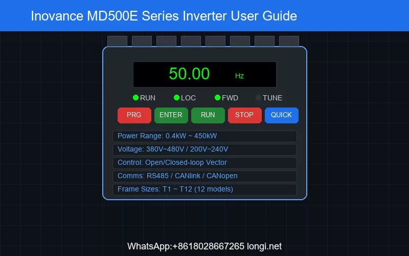
The MD500E series covers a power range from 0.4kW to 450kW, supporting both three-phase 380V~480V and three-phase 200V~240V voltage levels, with frame sizes from T1 to T12 (12 specifications in total). The core control methods include open-loop vector control (SVC) and closed-loop vector control (FVC). In SVC mode, the starting torque reaches 0.25Hz/150%, speed regulation range is 1:200, and speed stability accuracy is ±0.5%. In FVC mode, the starting torque reaches 0Hz/180%, speed regulation range is 1:1000, and speed stability accuracy is ±0.02%.

For frequency sources, the MD500E supports 10 types of frequency command inputs: digital setting (power-off memory/non-memory), analog input (AI1/AI2/AI3), pulse input (DI5, up to 100kHz), multi-speed, simple PLC, PID, and communication setting, with flexible switching between methods. Run commands support operation panel, control terminal, and serial communication port inputs. Communication supports three fieldbus protocols: RS485 (Modbus-RTU), CANlink, and CANopen.

Protection features include input/output phase loss protection, instantaneous overcurrent protection (trips at 250% of rated current peak), overvoltage protection (DC bus voltage above 820V), undervoltage protection (DC bus voltage below 350V), overheating protection, overload protection (trips after 60s at 150% rated current at 40°C), short circuit protection (output phase-to-phase and ground fault), and braking protection.

2. Installation and Wiring Essentials

Installation Environment: The MD500E inverter must be installed indoors with ambient temperature from -10°C to +50°C (derating required above 40°C, 1.5% per °C increase), humidity ≤95%RH non-condensing, and altitude below 1000m without derating (1% derating per 100m above 1000m). The mounting direction must be vertical; horizontal, side-lying, or inverted installation is prohibited. T1~T9 frames support wall-mounted and flush-mounted installation, while T10~T12 frames only support single-unit cabinet installation.

Thermal Design: When designing the cabinet, the effective area of air intake and exhaust openings must be considered. For example, a T3 (7.5kW) unit requires a minimum intake area of 50cm² and a minimum passive exhaust area of 80cm². For multiple inverters in one cabinet, the required cooling air volume must be accumulated, and the cabinet fan’s maximum air volume should be 1.3~1.5 times the total cooling air volume of all inverters.

Main Circuit Wiring: T1~T4 frame main circuit terminals include R/S/T (three-phase power input), U/V/W (motor output), and +/BR (braking resistor connection). T5 and above frames also feature DC bus positive and negative terminals (+) and (-) for common DC bus or external braking unit connection. Terminal screws must be tightened according to the specified torque values, ranging from 4.8N·m to 85N·m depending on the frame size.

Control Circuit Wiring: Standard control terminals include:

  • Power terminals: +10V (external potentiometer power, max 10mA), +24V (digital I/O power, max 200mA), OP (external power input, factory-default shorted to +24V)
  • Analog inputs: AI1 (0~10V voltage input), AI2 (0~10V voltage or 0~20mA current, selected by J9 jumper)
  • Digital inputs: DI1~DI4 (optocoupler isolated, 9V~30V operating voltage), DI5 (high-speed pulse input, up to 100kHz)
  • Output terminals: AO1 (analog output, 0~10V or 0~20mA, selected by J7 jumper), DO1 (digital output, 0~24V/50mA), FM (high-speed pulse output, up to 100kHz), T/A-T/B-T/C (relay output, 250V AC/3A or 30V DC/1A)
  • Communication: 485+/485- (RS485 interface)

Digital input terminals support both sink and source wiring modes. In sink wiring with internal 24V power, OP must be shorted to +24V; with external power, the shorting tab between OP and +24V must be removed. When paralleling DI terminals across multiple inverters, a diode (IF>40mA, VR>40V) must be connected in series to prevent malfunction.

3. LED Operation Panel Detailed Guide

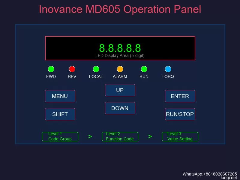
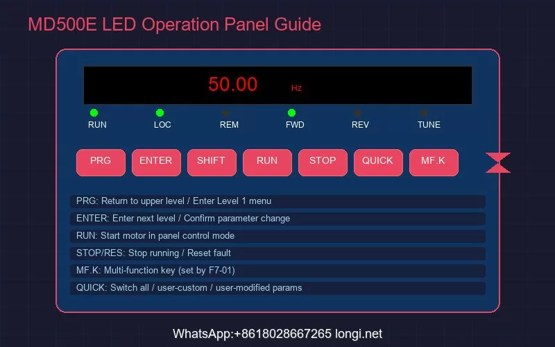
MD500E LED Operation Panel Guide

The MD500E is equipped with an LED operation panel that displays running status, enables parameter setting, and shows fault information. The panel uses a three-level menu structure: level 1 is the parameter group (e.g., F0, F1, F2), level 2 is the specific parameter (e.g., F0-02), and level 3 is the parameter setting value.

Key Functions:

  • PRG (Program key): Return to previous screen or enter level 1 menu
  • ENTER (Confirm key): Enter next screen, confirm parameter changes
  • Increment/Decrement keys: Increase or decrease parameter numbers and setting values
  • Shift key: Select the digit to modify when setting parameters
  • RUN key: Start the motor in panel control mode
  • STOP/RES key: Stop during running, reset during fault state
  • MF.K (Multi-function key): Function set by parameter F7-01
  • QUICK key: Switch between parameter display modes (all parameters / user-customized / user-modified)

Panel Indicators:

  • RUN lamp: Off = stopped, On = running
  • LOCAL/REMOT lamp: Off = panel control, On = terminal control, Blinking = communication control
  • FWD/REV lamp: Off = forward, On = reverse
  • TUNE/TC lamp: Off = normal, On = torque control, Slow blink = parameter identification (1/sec), Fast blink = fault (4/sec)

MF.K Multi-function Key: Parameter F7-01 offers 5 options: 0=disabled, 1=switch between panel and remote command channels, 2=forward/reverse switching, 3=forward jog, 4=reverse jog. The forward/reverse switching and jog functions are only effective when the command source is the operation panel. Parameter F7-02 controls the STOP/RESET key scope: 0=effective only in keyboard mode, 1=effective in all operation modes.

Quick Parameter Lookup: Press the QUICK key to switch between three parameter display modes — full parameter mode shows all function codes; user-customized mode shows up to 30 user-selected parameters (defined via FE group); user-modified mode automatically lists parameters that differ from factory defaults, enabling quick identification of changed settings.

4. Terminal Control and Run Configuration

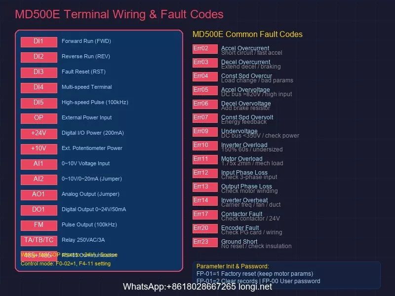
MD500E Terminal Wiring and Fault Codes

Parameter F0-02 selects the run command input channel: 0=operation panel, 1=terminal, 2=communication. When terminal control is selected (F0-02=1), parameter F4-11 sets the terminal command control mode, supporting four patterns:

Two-wire Mode 1 (F4-11=0): The most commonly used mode. For example, DI1 set to forward run (F4-00=1), DI2 set to reverse run (F4-01=2). SW1 closed = forward, SW2 closed = reverse; both open or both closed = motor stops.

Two-wire Mode 2 (F4-11=1): DI1 set to run command, DI2 set to forward/reverse direction. SW1 closed enables running; SW2 open = forward, SW2 closed = reverse.

Three-wire Mode 1 (F4-11=2): DI3 set to three-wire run control (normally closed button), DI1 set to forward run, DI2 set to reverse run. With SW3 closed, pressing SW1 starts forward, pressing SW2 starts reverse; opening SW3 stops the inverter.

Three-wire Mode 2 (F4-11=3): DI3 set to three-wire run control, DI1 set to run command, DI2 set to forward/reverse direction. With SW3 closed and SW1 pressed, the inverter runs; SW2 open = forward, SW2 closed = reverse.

Multi-speed Control: The MD500E supports up to 16-speed operation, selected by the combined signals of 4 DI terminals. Set F0-03=6 to select multi-segment command as the main frequency source, with each speed value set via FC-00~FC-15 parameters. The relationship between DI terminal count and speed count: 1 DI = 2 speeds, 2 DIs = 4 speeds, 3 DIs = 8 speeds, 4 DIs = 16 speeds.

Frequency Command Setting: In addition to multi-speed, the MD500E supports setting the main frequency via analog input (AI1/AI2/AI3), pulse input (DI5), panel digital setting, communication, simple PLC, and PID. Parameter F0-03 selects the main frequency source X, and F0-07 sets the frequency source superposition method, enabling flexible configurations such as addition/subtraction of main and auxiliary frequencies or taking the maximum value.

5. Parameter Initialization and Password Management

Factory Reset: Parameter FP-01 executes parameter initialization with the following options:

  • FP-01=0: No operation
  • FP-01=1: Restore factory parameters (Mode 1) — most function parameters are restored to factory defaults, but motor parameters, frequency decimal point (F0-22), fault records, cumulative running time (F7-09), cumulative power-on time (F7-13), cumulative power consumption (F7-14), and heatsink temperature (F7-07) are not restored
  • FP-01=2: Clear record information — clears fault records and cumulative running/power-on time/power consumption
  • FP-01=4: Backup current user parameters
  • FP-01=501: Restore user backup parameters

User Password: The FP parameter group includes user password functionality (FP-00), which can be set to protect parameters from unauthorized modification. Once a password is set, entering the correct password is required to edit parameters again. If the password is forgotten, contact the manufacturer or authorized service center for unlocking.

Parameter Group Display: Parameter FP-02 controls whether U, A, B, and C parameter groups are displayed on the operation panel. Parameter FP-03 controls the display of user-customized and user-modified parameter groups, streamlining menu navigation as needed.

Motor Parameter Identification: Correct motor parameter settings are essential for optimal vector control performance. After setting F1-00 (motor type, default 2 = permanent magnet synchronous motor), F1-01 (rated power), F1-02 (rated voltage), F1-03 (rated current), F1-04 (rated frequency), and F1-05 (rated speed) according to the motor nameplate, set F1-37=2 and press and hold the RUN key for more than 3 seconds to start parameter identification. During identification, the TUNE/TC indicator blinks slowly, and after approximately 1 minute, the panel displays 50.00 indicating completion.

6. Fault Code Reference and Troubleshooting

The MD500E inverter features comprehensive fault detection and protection mechanisms. Fault codes are prefixed with “Err” followed by a two-digit number. Below are common fault codes and troubleshooting methods:

Overcurrent Faults:

  • Err02 (Acceleration Overcurrent): Current exceeds 2.5 times rated current peak during acceleration. Check for output circuit short circuits, verify motor parameter identification was performed, check if acceleration time (F0-17) is too short, and verify overcurrent stall suppression parameters (F3-18/F3-19/F3-20)
  • Err03 (Deceleration Overcurrent): Current exceeds limit during deceleration. Extend deceleration time (F0-18) and check braking resistor configuration
  • Err04 (Constant Speed Overcurrent): Current exceeds limit during constant speed operation. Check for sudden load changes and verify motor parameter correctness

Overvoltage Faults:

  • Err05/Err06/Err07 (Acceleration/Deceleration/Constant Speed Overvoltage): DC bus voltage exceeds 820V. Deceleration overvoltage is common with high-inertia loads; configure braking resistors or increase deceleration time. Overvoltage stall function (F3-22/F3-23/F3-24/F3-25) can automatically limit voltage rise

Other Common Faults:

  • Err09 (Undervoltage): DC bus voltage below 350V — check input power supply
  • Err10 (Inverter Overload): Trips after 60s at 150% rated current at 40°C — check if load is too large or inverter is undersized
  • Err11 (Motor Overload): Based on inverse time curve, trips at 1.75× rated current for 2 minutes or 1.15× rated current for 80 minutes. Check motor load, F1 group motor parameters, and F9 group overload protection parameters
  • Err12/Err13 (Input/Output Phase Loss): Check three-phase input power balance and output-to-motor wiring reliability
  • Err14 (Inverter Overheating): Check if carrier frequency (F0-15) is too high, fan is damaged, or air duct is blocked
  • Err17 (Contactor Fault): Check soft-start contactor cable and 24V power supply
  • Err20 (Encoder Fault): Check encoder wiring and PG card configuration; verify encoder line count, type, and direction settings
  • Err23 (Output Ground Short Circuit): This fault cannot be reset — use a megger to check motor and output cable insulation

Fault Reset and Diagnosis: Most faults can be reset by pressing the STOP/RES key or power cycling (except Err23). For overcurrent or overload faults during startup in open-loop vector control mode (F0-01=0), focus on verifying motor parameter identification completion and checking speed loop parameters (F2-00/F2-01 for low frequency, F2-03/F2-04 for high frequency). In closed-loop vector control mode (F0-01=1), also confirm encoder wiring, line count, and direction settings are correct.

7. Routine Maintenance and Care

To ensure long-term stable operation of the MD500E inverter, the following periodic inspections are recommended:

  • Daily inspection: Observe for abnormal running conditions (noise, odor, temperature anomalies), verify cooling fan operation, and confirm air intake/exhaust openings are unobstructed
  • Periodic inspection: Check main circuit terminal screws for looseness (re-tighten to specified torque), measure main circuit insulation resistance (disconnect control board and use 500V megger), and inspect electrolytic capacitors for swelling or leakage
  • Consumable replacement: Cooling fan life is approximately 20,000~30,000 hours (depending on environment), and filter capacitor life is approximately 5~8 years; replace when end of life is reached
  • Storage requirements: For long-term storage, maintain ambient temperature at -20°C~+60°C and power on for a test run every 6 months to maintain electrolytic capacitor performance

Conclusion

The Inovance MD500E series inverter, with its rich control functions, flexible configuration options, and comprehensive protection mechanisms, can meet the driving requirements of various industrial automation scenarios. Correctly understanding the operation panel usage, properly configuring terminal control schemes, following standardized parameter setting procedures, and mastering fault diagnosis techniques are key to fully leveraging the product’s performance. In practical applications, technicians are advised to conduct meticulous commissioning according to the official manual based on specific working conditions, and establish a regular maintenance system to ensure long-term reliable equipment operation.

For more technical support, product selection, or repair services regarding Inovance inverters, please contact professional industrial control service providers.

Posted on

Inovance MD605 Series Inverter User Guide: Operation Panel, Terminal Control, and Fault Troubleshooting

The Inovance MD605 series compact inverter is a high-performance, cost-effective solution designed for small automation equipment across industries including silicon crystal manufacturing, lithium battery production, woodworking, logistics, cable processing, packaging, and machine tools. This comprehensive guide covers the operation panel functionality, password and parameter access management, external terminal forward/reverse control wiring, and complete fault code troubleshooting procedures based on the official MD605 series manual.

Inovance MD605 LED operation panel with keypad buttons and parameter menu levels
Inovance MD605 LED operation panel showing five-digit display and six membrane keypad buttons

1. Operation Panel Function Overview

1.1 Panel Structure and Display

The MD605 series comes standard with an LED operation panel featuring five 8-segment LED displays and six thin-film keypad buttons. The panel is divided into three functional zones: status display area, function code display area, and keypad control area.

The five-digit LED display shows multiple types of information: set frequency, output frequency, bus voltage, output voltage, output current, output power, output torque, DI input status, DO output status, AI1 voltage value, and fault codes. Status indicators on the panel show running direction (FWD/REV), local/remote mode, torque control mode, alarm status, and running status.

The panel supports a three-level menu structure for parameter configuration:

  • Level 1: Function code group (F0, F1, A0, etc.)
  • Level 2: Specific function code within the group
  • Level 3: Function code value setting

When a digit is flashing in any menu level, the UP and DOWN keys modify that digit’s value, while the SHIFT key moves between digits. Pressing ENTER saves the parameter and moves to the next parameter; pressing the MENU/RETURN key aborts the current edit and returns to the previous menu.

1.2 Parameter Monitoring Configuration

The operation panel supports customizable monitoring displays through parameters A6-03, A6-04 (running state display), and A6-05 (stopped state display). Each parameter uses 16 bits to enable or disable specific monitoring values. For example, setting A6-03 bit0 to 1 displays running frequency, while bit1 shows set frequency.

The MD605 also supports two free-mapping display parameters (A6-07/A6-08 for mapping 0, A6-09/A6-10 for mapping 1), allowing any word connector value to be displayed with custom units and decimal places on the LED panel.

2. Password Setting, Elimination, and Parameter Access Restriction

2.1 Parameter Access Levels

The MD605 implements a four-tier parameter access system to protect critical settings:

Access LevelCodeDescription
Standard0Default level, accesses basic inverter parameters
Extended1Includes user customization parameters and frequency detection functions
Expert2Complex motor performance tuning parameters, requires password
Manufacturer3Password-locked, reserved for factory service only

Current access level is displayed in parameter A0-10. The target access level is set through A0-11.

2.2 Expert Password Management

To prevent unauthorized modification of expert parameters:

Setting Expert Password:

  1. Navigate to parameter A0-16 (Expert Password Setting)
  2. Enter a non-zero value (range: 0-65535)
  3. The password takes effect immediately; A0-14 shows “Expert password locked”

Unlocking Expert Access:

  1. Switch to Extended parameter level (A0-11 = 1)
  2. Navigate to A0-15 (Expert Password Input)
  3. Enter the correct password matching A0-16
  4. A0-14 changes to “Expert password unlocked”
  5. Now set A0-11 = 2 to access Expert parameters

Password Timeout: After unlocking, Expert access automatically expires after 1 hour of inactivity. The password can also be cleared by modifying A0-16 or changing A0-11 to a lower level.

2.3 Parameter Lock Function

For complete parameter protection at the field level:

Setting Parameter Lock:

  1. Navigate to A0-31 (Parameter Lock Setting)
  2. Enter a non-zero password value (0-65535)
  3. All parameter menus are immediately locked

Unlocking Parameter Lock:

  1. Enter the correct password when prompted
  2. A0-30 shows “Parameter lock unlocked”
  3. The lock automatically re-engages after the duration set in A0-32 (default: 3600 seconds)
  4. Manual re-locking is possible anytime by setting A0-33 = 1

Removing Password: Set A0-31 = 0 to disable the parameter lock entirely.

3. Restoring Factory Default Settings

Parameter initialization is performed through parameter A0-00 (Parameter Initialization) with three options:

Setting ValueFunction
1Restore factory parameters excluding motor parameters
3Restore factory parameters including motor parameters
503Restore factory parameters including motor parameters, and clear all record information

Procedure:

  1. Navigate to A0-00
  2. Enter the desired initialization code (1, 3, or 503)
  3. Press ENTER to confirm
  4. The inverter automatically restarts with default parameters

Note: Manufacturer parameters are never restored by any initialization option. For motor parameter preservation during troubleshooting, use setting value 1.

MD605 CN4 terminal block wiring diagram and common fault code reference table
MD605 CN4 control terminal block wiring and common fault code reference

4. External Terminal Forward/Reverse Control

4.1 Control Terminal Wiring

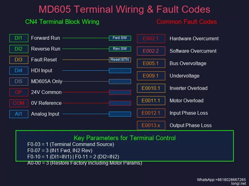
The MD605 control terminals are located on the CN4 12-pin terminal block. Key terminals for external control:

TerminalNameFunction
DI1Digital Input 1Programmable, default: Terminal Start/Stop Module A IN1
DI2Digital Input 2Programmable, default: Terminal Start/Stop Module A IN2
DI3Digital Input 3Programmable, default: RESET function
DI4Digital Input 4High-speed pulse input (HDI), max 20kHz
DI5Digital Input 5(MD605A model only) Programmable
OPDI Power CommonDefault connected to internal 24V; switch to external via S4 dip switch
COM24V Reference GroundIsolated from GND internally
AI1Analog Input 1-10V to +10V or 0-20mA, 12-bit resolution
10V10V Reference Output10V +/-5%, max 10mA
GNDAnalog GroundIsolated from COM
TA/TB/TCRelay OutputProgrammable relay contacts

Wiring for External Control:

For the most common sink-type wiring using internal 24V power:

  1. Set S4 dip switch to the 24V position (OP connected to internal 24V)
  2. Connect an external controller’s 0V/GND to the inverter COM terminal
  3. Connect controller output signals to DI1, DI2, etc.
  4. When a DI terminal receives 15V-30V (via closed contact), the corresponding function activates

Important: Never short-circuit COM and OP terminals when OP is connected to internal 24V – this will damage the internal power supply.

4.2 Parameter Configuration for Forward/Reverse Control

To enable external terminal control, configure these parameters:

Step 1: Select Terminal Command Source

  • Set F0-03 (Control Channel 1 Main Command Source) = 1 [Terminal]
  • Alternatively, this is mapped to b1-00 with identical functionality

Step 2: Configure Terminal Mode

Set F0-07 (Terminal Start/Stop Module A Mode) according to your wiring scheme:

  • 1: IN1 controls start
  • 2: IN1 starts, IN2 controls direction
  • 3: IN1 forward start, IN2 reverse start (most common for forward/reverse)
  • 4: IN1 pulse start, IN2 stop
  • 5: IN1 pulse start, IN2 stop, IN3 direction
  • 6: IN1 pulse forward, IN2 pulse reverse, IN3 stop

Step 3: Assign DI Terminal Functions

  • F0-10 (DI1 Terminal Function) = 1 [Terminal Module A IN1] – Forward run
  • F0-11 (DI2 Terminal Function) = 2 [Terminal Module A IN2] – Reverse run / Direction
  • F0-12 (DI3 Terminal Function) = 9 [Fault Reset] – Optional reset function

Example: Independent Forward/Reverse Control

For the most straightforward two-wire forward/reverse setup:

  1. F0-03 = 1 (Terminal command source)
  2. F0-07 = 3 (IN1 forward, IN2 reverse)
  3. F0-10 = 1 (DI1 = IN1, forward start)
  4. F0-11 = 2 (DI2 = IN2, reverse start)
  5. Wire controller forward contact to DI1-COM
  6. Wire controller reverse contact to DI2-COM
  7. Ensure both contacts use the same COM reference

When DI1 receives a signal, the motor runs forward. When DI2 receives a signal, the motor runs reverse. If both signals are active simultaneously, the inverter determines priority based on internal logic.

5. Fault Codes and Troubleshooting

The MD605 uses a three-segment fault code format: E-XXX.Y where E indicates fault severity, XXX is the main code, and Y is the sub-code.

5.1 Overcurrent Faults

E002.1 – Hardware Overcurrent
Triggered when instantaneous output current exceeds 4.24 times the inverter rated current (A3-03).

Causes and Solutions:

  • Output ground fault: Measure output terminal-to-ground impedance with a megohmmeter; should be mega-ohm level. Replace grounded motor or cable.
  • Output phase short: Measure UV, VW, WU resistance with multimeter; values should be symmetrical. Replace shorted components.
  • Speed loop parameters too aggressive (SVC): Reduce speed loop Kp (F2-02) by half, set Ti (F2-03) to 2s. Test and repeat if needed.
  • Synchronous motor demagnetization: Record back-EMF (F1-12), perform dynamic identification (F1-69=12), compare new value. Analyze root cause before replacing motor.
  • Unidentified motor parameters (SVC): Perform accurate parameter identification per manual procedures.
  • High carrier frequency needed: For high-speed motors, ensure carrier frequency > 12 x output frequency. Increase A5-01 if necessary.
  • Motor rotating at startup: Enable speed tracking startup (d0-02 = 1).
  • V/f oscillation: Adjust V/f oscillation suppression gain (d2-23), or switch to SVC control (F0-01 = 0).

E002.2 – Software Overcurrent
Triggered when current exceeds the custom software overcurrent point (A3-54).

Additional causes include:

  • Overcurrent suppression misconfigured: Check d2-26=1, adjust d2-27, d2-28, d2-29
  • Torque boost too high: Reduce manual torque boost (d2-14), perform static identification (F1-69=1)
  • Acceleration/deceleration time too short: Extend ramp times (F0-48, F0-49)
  • V/f curve voltage excessive: Reduce voltage/frequency ratio in multi-point V/f settings

5.2 Overvoltage Faults

E005.1 – Bus Overvoltage
Triggered when DC bus voltage exceeds the overvoltage activation point (A3-58).

Causes and Solutions:

  • Insufficient braking power: Extend deceleration time, increase braking resistor power, enable overvoltage suppression (d1-54=1 for non-hoisting loads)
  • Load dump causing overshoot: Increase speed loop Kp (F2-02), set Ti (F2-03) to 2s, enable S-curve (b7-00=1)
  • Deceleration time too short: Extend F0-49 (ramp 1 deceleration time), add braking resistor if needed
  • Input voltage too high: Verify input voltage is within rated range (380V-480V for 380V class, 220V-240V for 220V class)
  • Braking unit voltage set too high: Lower braking unit activation voltage (A4-00) if needed

E005.2 – Overvoltage Suppression Active
System-level warning; contact technical support if persistent.

5.3 Undervoltage Faults

E009.1 – Undervoltage Fault
Triggered when DC bus voltage falls below the undervoltage activation point (A3-56).

Causes and Solutions:

  • Input phase loss: Measure RS, ST, RT line voltages with multimeter AC mode; check for symmetry. Inspect input switches, contactors, and terminals.
  • Grid voltage dip (most common cause): Enable undervoltage suppression (d1-63=1) for fan/pump/compressor loads. The inverter converts motor kinetic energy to electrical energy to maintain bus voltage.
  • Input voltage too low: Increase input voltage to rated range, ensure upstream breakers/contactors are closed and functional.
  • Undervoltage suppression parameters incorrect: Adjust undervoltage suppression Kp/Ki (d1-66/67). Start with smaller values and increase if ineffective.
  • Motor oscillation causing undervoltage: Resolve motor oscillation issues by adjusting control parameters.

E009.2 – Undervoltage Suppression Active
System-level warning indicating active suppression. Hardware fault requires technical support.

E009.3 – Pre-Drive Timeout
Bus voltage remains below undervoltage point after startup command within timeout period.

  • Check input wiring per manual diagrams
  • Verify input voltage is within specification
  • If input is confirmed correct, hardware damage likely – contact technical support

5.4 Overload Faults

E0010.1 – Inverter Overload
Inverter cumulative overload coefficient (LC-32) reaches 100%.

Causes and Solutions:

  • Load too heavy or motor blocked: Check if load is abnormally heavy, verify brake is releasing properly
  • For asynchronous motors at low/mid speed: Increase no-load current (F1-30), decrease mutual inductance (F1-28), maintain their product constant
  • For synchronous motors at low/mid speed: Increase MTPA adjustment coefficient (d5-29) for salient-pole motors
  • High-speed weak magnetic zone overload: Increase modulation index (A5-06), keep below 108%
  • V/f acceleration time too short: Extend F0-48/49, enable overcurrent suppression (d2-26=1)
  • Motor parameter error: Verify motor nameplate matches F1-00 through F1-11 settings
  • Inverter undersized: Recalculate load requirements and select larger inverter if necessary

E0011.1 – Motor Overload
Motor cumulative overload coefficient (LC-33) reaches 100%.

  • Verify load is not mechanically overloaded
  • Check motor overload protection coefficient (d1-46); increase if actual motor temperature is low but fault persists
  • Confirm motor parameters match nameplate data
  • Verify input voltage is within specification
  • For prolonged overload, consider upsizing motor or inverter

5.5 Phase Loss Faults

E0012.1 – Input Phase Loss
Detected by hardware circuit when input phase is missing.

  • Verify input wiring is correct per manual
  • Check input voltage is within range
  • If input is confirmed correct and voltage normal, inverter diode damage likely – contact technical support

E0013.1/E0013.2/E0013.3 – U/V/W Phase Loss
Running current in one phase is significantly lower than the other two phases.

  • Check output wiring for open circuits
  • Verify output contactor is closed (not tripped)
  • Test motor: check for line breaks, measure UV/UW/VW resistances for balance
  • If resistances are unbalanced, repair or replace motor

5.6 Fault Reset Methods

After resolving the root cause, reset the fault using one of these methods:

  1. DI Terminal Reset: Configure any DI terminal (E0-00 through E0-04) to function 9 [Fault Reset], then activate that terminal
  2. Panel Reset: Press the RUN/STOP key on the LED panel while in fault state
  3. Power Cycle: Disconnect main power, wait until display goes dark, then reconnect power
  4. Communication Reset: When in communication control mode (b1-00=2), write value “16” (bit4 fault reset command) to communication address 7321H

For persistent or unclear faults, do not attempt internal repairs. Contact Inovance technical support or an authorized distributor for professional assistance.


This guide provides the essential procedures for operating the Inovance MD605 series inverter safely and effectively. Always follow safety precautions, verify wiring before energizing, and perform parameter identification when using vector control modes for optimal performance.

Posted on

From “Abnormal DC Component in Inverter Voltage” to High-Voltage Insulation Leakage: Structure, Operating Principle, Fault Diagnosis, and Repair of a 630 kVA Modular Shore Power Frequency Converter

Abstract

Shore power frequency conversion systems are used to convert utility power supplied by a port into stable electrical power that meets the voltage, frequency, grounding, and power-quality requirements of a vessel. Because shore-side and shipboard electrical systems may operate at different voltage and frequency standards, large shore power installations commonly adopt a combination of input transformer, static frequency converter, output transformer, switching equipment, and supervisory control.

This article examines a 630 kVA shore power frequency conversion system rated for 380 V, 50 Hz input and 440 V, 60 Hz output. The system contains two parallel 400 kVA converter units, each built from eight parallel power modules. During startup, all inverter modules simultaneously reported:

  • 05E-07: Abnormal DC component in inverter voltage
  • 05A-02: Inverter self-test error

The inverter output remained at approximately 164 V and 31.9 Hz during the no-load self-test stage. A handheld multimeter also indicated approximately 90 VDC between each output phase and neutral, leading initially to suspicion of a PFC, DC-bus, voltage-sensing, or common control fault.

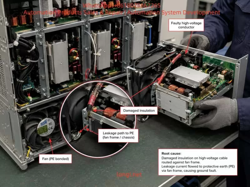
Further investigation showed that the real cause was much more specific. Inside one power module, a high-voltage conductor had damaged insulation and was touching or leaking through the fan frame and protective-earth path. The resistance between the conductor and ground was only about 300 Ω, whereas the corresponding point in a healthy module was effectively open circuit. The fault pulled a normally higher-voltage node down from approximately 250 V to slightly above 100 V and contaminated an isolated auxiliary supply of about 14 V with a common-mode voltage of several hundred volts.

Because corresponding auxiliary and control circuits were interconnected across the eight parallel modules, the abnormal common-mode potential affected the inverter gate-drive and voltage-detection references of the entire converter. This caused all modules to report the same inverter DC-component fault. After the damaged conductor was insulated and mechanically repositioned, the module and complete converter returned to normal operation.

The case demonstrates that a system-level inverter failure does not necessarily originate from failed IGBTs, a defective PFC stage, or a faulty master controller. High-voltage wiring, fan assemblies, auxiliary power supplies, grounding paths, mechanical abrasion, and common-mode coupling can produce the same alarm pattern and must be included in the diagnostic process.

Keywords: shore power converter, modular UPS, PFC boost stage, three-level inverter, inverter DC offset, auxiliary power supply, insulation failure, earth leakage, parallel power module, high-voltage wiring


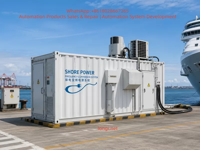
Containerized shore power frequency conversion system installed at a harbor for ship electrical power supply, showing industrial enclosure, cooling units, power cables, and maritime infrastructure

1. Why a Shore Power System Cannot Be Treated as an Ordinary Variable-Frequency Drive

The basic purpose of shore power is to supply a vessel from the port electrical grid while the vessel is berthed. This allows onboard diesel generators to be shut down or operated at reduced output, decreasing fuel consumption, exhaust emissions, noise, and vibration.

However, shore power is not simply a matter of connecting a three-phase cable from the port to the vessel. Shore-side and shipboard distribution systems may differ in several important ways.

A port electrical network may provide:

  • 380 V, 50 Hz;
  • 400 V, 50 Hz;
  • three-phase four-wire power;
  • a neutral directly associated with the shore grounding system.

A vessel may require:

  • 440 V, 60 Hz;
  • 450 V, 60 Hz;
  • 460 V, 60 Hz;
  • 480 V, 60 Hz;
  • three-phase three-wire power;
  • a different grounding or neutral arrangement.

The vessel may also contain a large number of motors, pumps, compressors, air-conditioning systems, galley loads, navigation equipment, control systems, and nonlinear rectifier loads. These loads may require tighter limits on voltage, frequency, harmonic distortion, grounding, and electrical isolation than ordinary industrial loads.

A transformer can change voltage but cannot change frequency. If the shore supply is 50 Hz and the vessel requires 60 Hz, a transformer alone is insufficient. The system must use either a rotating motor-generator set or a static semiconductor frequency converter.

The equipment examined in this case had the following nameplate data:

  • System capacity: 630 kVA
  • Input: AC 380 V, 50 Hz, 3P+N+PE
  • Output: AC 440 V, 60 Hz, 3P+PE
  • Input transformer cabinet included
  • Output transformer cabinet included
  • Two converter sections identified as frequency converter No. 1 and No. 2

The installation was therefore not a conventional motor-drive VFD. It was a complete shore power frequency conversion system consisting of transformers, parallel static converters, switching devices, output distribution, and monitoring equipment.

Its power-conversion hardware was based on a high-power online UPS platform, but in this application it primarily functioned as a static frequency converter rather than as a conventional battery-backed data-center UPS.


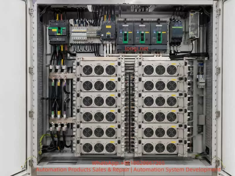
Internal structure of a high-power shore power frequency converter cabinet with modular inverter units, cooling fans, circuit breakers, busbars, and industrial power distribution components

2. Overall Power-Conversion Path of the System

Based on the field nameplates, single-line diagrams, switchgear layout, and internal module construction, the system can be represented as follows:

Port utility supply
Three-phase 380 V, 50 Hz
          │
          ▼
Input switchgear and input transformer
          │
          ▼
Two parallel 400 kVA converter units
          │
          ▼
Three-phase active rectifier / PFC stage
          │
          ▼
High-voltage split DC bus
          │
          ▼
Three-phase PWM inverter
          │
          ▼
Output LC filtering
          │
          ▼
Parallel output bus and isolation switches
          │
          ▼
Output transformer
          │
          ▼
Shipboard supply
Three-phase 440 V, 60 Hz

This is an AC-to-DC-to-AC double-conversion system.

The front-end converter rectifies the input and controls the DC bus. The rear inverter reconstructs an output waveform whose voltage and frequency are independent of the input frequency.

This structure provides several advantages:

  • 50 Hz input can be converted to 60 Hz output.
  • Output voltage can be regulated independently of the utility voltage.
  • Input voltage disturbances do not pass directly to the vessel.
  • Input power factor can be controlled.
  • Input current harmonics can be reduced.
  • Multiple modules can operate in parallel.
  • Redundancy can be implemented.
  • A battery can be connected if backup operation is required.
  • A bypass path can be incorporated for maintenance or emergency operation.

In this project, no external battery bank was installed. The “Battery+,” “Battery N,” and “Battery−” terminals remained part of the power-module architecture because the converter hardware was derived from an online UPS platform. The absence of a battery did not prevent normal AC-to-AC operation because the PFC stage established the DC bus directly from the utility input.


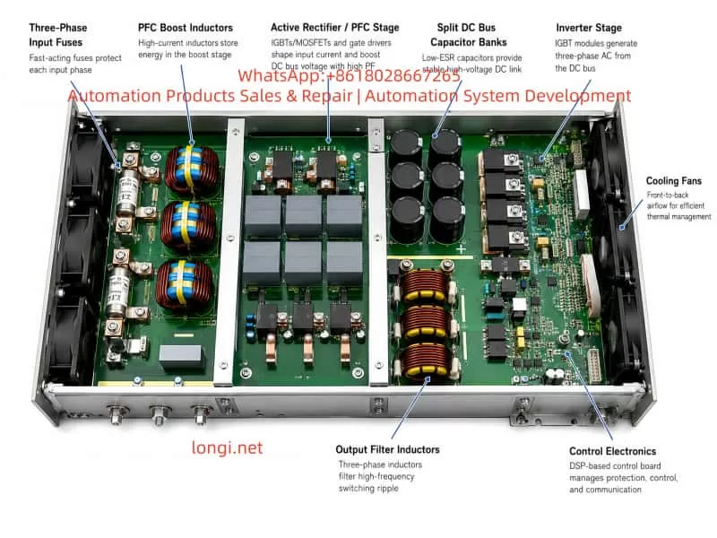
Technical illustration of a power converter module showing PFC boost inductors, active rectifier stage, DC bus capacitors, inverter stage, output filter inductors, cooling fans, and control electronics

3. The Power Module Is a Complete Double-Conversion Converter, Not Merely an Inverter Board

Markings visible on the removed module included designations such as:

YDC3300 MOD5.PCB

The internal construction confirmed that each module contained far more than a single inverter bridge. It was a complete modular power-conversion unit incorporating:

  • input protection;
  • EMI filtering;
  • three-phase PFC;
  • high-voltage DC energy storage;
  • inverter switching;
  • output filtering;
  • isolated auxiliary power;
  • gate-drive circuitry;
  • voltage and current sensing;
  • digital control and communication.

A simplified module structure is:

Three-phase AC input
        │
        ▼
Input fuses and EMI filter
        │
        ▼
Three-phase boost inductors
        │
        ▼
Active rectifier / PFC bridge
        │
        ▼
Split DC bus
DC+ — N — DC-
        │
        ▼
Three-phase three-level inverter
        │
        ▼
LC output filter
        │
        ▼
Three-phase AC output

The major physical sections can be identified directly from the photographs.


Fault diagnosis of a shore power converter module showing damaged high-voltage cable insulation, leakage path to protective earth, cooling fan grounding connection, and maintenance inspection process

4. Major Internal Sections of the Module

4.1 Three-Phase Input Fuses

Three large cylindrical fuses were installed in the input section, corresponding to the three input phases.

Their functions include:

  • isolating an internal module short circuit;
  • protecting the PFC switching devices;
  • preventing a failed module from damaging the common input bus;
  • limiting fault energy during semiconductor failure;
  • allowing each power module to be serviced independently.

In a parallel modular system, individual input protection is essential. Without it, a short circuit inside one module could collapse the input supply for all remaining modules.

4.2 PFC Boost Inductors

The module contained several large copper-wound magnetic components. The three inductors closest to the input section were consistent with three-phase PFC boost inductors.

These components were not line-frequency transformers. They functioned as energy-storage inductors in a high-frequency switched power stage.

Their roles included:

  • storing energy during each switching cycle;
  • supporting DC-bus voltage boost;
  • shaping the input current;
  • reducing current ripple;
  • helping maintain a high input power factor;
  • limiting current change during transient conditions.

A high-power three-phase PFC may use a Vienna rectifier, a three-level active rectifier, or another boost-type PWM rectifier topology. Regardless of the exact topology, the control system monitors input voltage, input current, and DC-bus voltage, then adjusts switching duty cycles to regulate both the DC bus and the shape of the input current.

4.3 Split DC-Bus Capacitor Banks

Large numbers of high-voltage electrolytic capacitors were arranged around the power section.

The external terminals were marked:

Battery+
Battery N
Battery-

This strongly indicated a split DC-bus structure:

DC+
 │
Upper DC-bus capacitor bank
 │
DC midpoint N
 │
Lower DC-bus capacitor bank
 │
DC-

When a battery system is installed, the positive terminal, midpoint, and negative terminal of the battery bank can be connected to these bus points.

When no battery is installed, the active rectifier still charges and regulates the upper and lower DC-bus capacitor banks.

A split DC bus is especially suitable for three-level rectifier and inverter circuits. Instead of switching only between DC+ and DC−, the inverter can also use the midpoint potential. This reduces voltage stress on individual power semiconductors and decreases the voltage step applied to the output filter.

4.4 PFC Power Semiconductors

Under the large aluminum heatsinks were likely combinations of:

  • IGBTs;
  • power MOSFETs;
  • fast-recovery diodes;
  • silicon-carbide diodes;
  • clamping devices;
  • current-sensing elements;
  • snubber components.

The PFC controller uses measured three-phase voltage and current signals to generate switching commands. The purpose is not merely to rectify the input, but also to regulate the positive and negative DC buses and keep their midpoint balanced.

4.5 Three-Phase Inverter Bridge

The power devices closer to the output section formed the inverter stage.

The module architecture and three-terminal DC bus were consistent with a three-level inverter. A three-level circuit offers several advantages over a basic two-level inverter:

  • lower voltage stress per switching device;
  • smaller output voltage steps;
  • reduced high-frequency harmonic content;
  • potentially lower switching loss;
  • easier output filtering;
  • better suitability for large modular UPS and static frequency-converter applications.

Each phase leg switches among the positive bus, midpoint, and negative bus. The three phases are modulated 120 electrical degrees apart to synthesize a balanced three-phase output.

4.6 Output Inductors and Filter Capacitors

The inverter bridge does not directly produce a clean sine wave. Its raw output is a high-frequency PWM waveform.

The module therefore contains output magnetic components and capacitors forming a filter network. These may include:

  • differential-mode inductors;
  • common-mode inductors;
  • phase filter capacitors;
  • neutral-point capacitors;
  • damping resistors or damping networks.

The filter attenuates the high-frequency switching component while preserving the required 50 Hz or 60 Hz fundamental.

4.7 Isolated Auxiliary Supplies and Gate Drivers

A large power converter contains many isolated auxiliary supplies.

Typical rails may include:

  • +15 V;
  • −5 V for negative gate turn-off;
  • +12 V or +14 V;
  • +5 V;
  • +3.3 V;
  • 24 V control supply.

The high-side, low-side, and midpoint switching devices operate at different high-voltage potentials. Each gate-driver circuit must therefore be powered by an isolated supply referenced to the local emitter or source of its corresponding switching device.

This detail became central to the fault.

An isolated 14 V supply can be perfectly normal when measured between its local positive and local negative terminals, while the entire isolated circuit may float hundreds of volts above protective earth.

The correct interpretation depends entirely on the measurement reference.


5. How a 380 V Input Can Produce a 440 V Output

A common question is:

If the input is only 380 V and there is no large step-up transformer inside each power module, how can the system produce 440 V?

The answer involves three separate stages:

  1. PFC raises and regulates the DC-bus voltage.
  2. The inverter reconstructs controlled AC from the elevated DC bus.
  3. The system output transformer performs final voltage matching and isolation.

5.1 Natural DC Voltage from Three-Phase Rectification

For a three-phase 380 V line-to-line input, the line-voltage peak is:

[
V_{\text{peak}}=380\sqrt{2}\approx537\text{ V}
]

The average DC voltage from a conventional six-pulse diode bridge is approximately:

[
V_{DC}\approx1.35V_{LL}
]

Therefore:

[
V_{DC}\approx1.35\times380\approx513\text{ V}
]

Without active boosting, the DC bus would normally remain in the range of approximately 510 to 540 V, depending on load, line voltage, and rectifier configuration.

5.2 Why a 500 V DC Bus May Not Be Sufficient

The maximum AC voltage that an inverter can synthesize is limited by its DC-bus voltage.

For a three-phase inverter using space-vector modulation, the theoretical maximum line-to-line RMS voltage is approximately:

[
V_{LL,\max}\approx\frac{V_{DC}}{\sqrt{2}}
]

To produce 440 V line-to-line directly, the theoretical minimum DC bus is therefore approximately:

[
V_{DC}\approx440\sqrt{2}\approx622\text{ V}
]

This figure does not include practical design margin.

A real system must also compensate for:

  • semiconductor voltage drop;
  • DC-bus ripple;
  • output-filter voltage drop;
  • input-voltage variation;
  • load transients;
  • modulation margin;
  • overload requirements;
  • harmonic-performance requirements.

Consequently, if the inverter itself must directly generate 440 V, the DC bus will normally be regulated above the theoretical minimum, potentially in the range of approximately 650 to 800 V depending on the exact circuit.

5.3 How the PFC Inductor Produces Voltage Boost

The PFC stage uses the same fundamental principle as a boost converter.

When a switching device turns on, current increases through the input inductor and energy is stored in its magnetic field:

[
E=\frac{1}{2}LI^2
]

When the switch turns off, the inductor current cannot stop instantly. The inductor generates a voltage that maintains current flow. This induced voltage adds to the rectified input voltage and transfers energy into the DC-bus capacitors.

The process can be represented as:

Switch ON
Input source → inductor stores energy

Switch OFF
Input source + inductor discharge voltage
                     ↓
          charges the DC-bus capacitors

For an ideal boost converter:

[
V_{out}=\frac{V_{in}}{1-D}
]

where (D) is the switching duty ratio.

As duty ratio increases, the theoretical output voltage rises. However, this equation is only an idealized model. A real industrial converter cannot increase voltage indefinitely.

The maximum usable DC-bus voltage is limited by:

  • IGBT or MOSFET voltage rating;
  • diode reverse-voltage rating;
  • capacitor voltage rating;
  • busbar insulation;
  • PCB creepage and clearance;
  • gate-drive isolation;
  • voltage-sensor range;
  • software overvoltage threshold;
  • inductor saturation;
  • switching loss;
  • thermal performance;
  • transient voltage overshoot.

For this type of 380/400 V three-phase modular converter, an engineering estimate for the normal total split-bus voltage is approximately 650 to 800 V, with each half bus approximately 325 to 400 V relative to the midpoint.

The actual target must be confirmed from the service manual, internal measurement menu, or comparison with the healthy No. 2 converter.

5.4 The Role of the Output Transformer

The field nameplate and system diagrams confirmed that an output transformer cabinet was part of the installation.

Therefore, the power modules did not necessarily have to generate the final 440 V directly.

A likely arrangement was:

Converter output
Approximately 380 or 400 V, 60 Hz
             │
             ▼
Output isolation transformer
             │
             ▼
Shipboard output
440 V, 60 Hz

If the inverter common bus produced 400 V, the required transformer ratio would be:

[
\frac{440}{400}=1.10
]

If the inverter produced 380 V, the ratio would be:

[
\frac{440}{380}\approx1.158
]

The output transformer could also perform several additional functions:

  • shore-to-ship galvanic isolation;
  • grounding-system conversion;
  • three-phase four-wire to three-phase three-wire conversion;
  • common-mode current limitation;
  • switching-noise suppression;
  • fault-protection coordination.

The system nameplate stated:

  • Input: 3P+N+PE
  • Output: 3P+PE

The absence of an output neutral supports the conclusion that the output transformer was also used to create the required three-wire shipboard system.


6. Fault Symptoms Observed in the Field

The system contained two parallel converter units. Converter No. 2 operated normally. Converter No. 1 failed during inverter startup.

Each converter contained eight parallel power modules.

The faulty converter reported:

  • 05E-07: Abnormal DC component in inverter voltage
  • 05A-02: Inverter self-test error

The alarms were associated with:

  • INV01
  • INV02
  • INV03
  • INV04
  • INV05
  • INV06
  • INV07
  • INV08

All eight modules reported almost the same fault within approximately one or two seconds.

The input readings were normal:

  • line voltage approximately 396 to 402 V;
  • frequency 50 Hz;
  • balanced three-phase voltage;
  • only several amperes of standby or self-test current.

During the failed no-load inverter self-test, the display showed:

  • output line voltage approximately 163 to 165 V;
  • output phase voltage approximately 94 to 95 V;
  • frequency 31.9 Hz;
  • output current 0 A;
  • output power 0 kW.

The relationship between phase voltage and line voltage was correct:

[
95\sqrt{3}\approx164.5\text{ V}
]

This indicated that the inverter had already begun generating a balanced low-voltage, low-frequency three-phase waveform. It failed before reaching rated voltage and frequency.


7. Why the Fault Was Initially Suspected to Be Related to PFC, the DC Bus, or Voltage Sensing

When eight modules report the same inverter fault simultaneously, it is reasonable to suspect a shared condition.

Initial candidates included:

  • PFC stage;
  • DC-bus imbalance;
  • common output-voltage sensing;
  • neutral reference;
  • master inverter controller;
  • PWM synchronization;
  • shared auxiliary supply;
  • shared communication or current-sharing signals.

This diagnostic direction was logical, even though the final root cause was different.

7.1 The Input Side Appeared Normal

The input voltage and frequency were stable, and the system event log indicated:

  • rectifier supplied by input source;
  • PFC active.

There were no clear alarms for:

  • rectifier failure;
  • DC-bus overvoltage;
  • DC-bus undervoltage;
  • input phase loss;
  • severe input imbalance;
  • failure to establish the DC bus.

This made a major PFC-stage failure less likely.

7.2 The Three-Phase Output RMS Values Were Balanced

A severe failure of one inverter phase would commonly produce:

  • one phase significantly low or high;
  • major voltage imbalance;
  • overcurrent;
  • fuse operation;
  • a phase-leg or driver fault specific to one module.

Instead, the three output RMS values were closely matched.

7.3 All Eight Modules Reported the Same Alarm

The probability that all eight power modules independently developed the same semiconductor failure at the same time was extremely low.

A more plausible explanation was:

  • one common signal affected every module;
  • one defective module contaminated a shared circuit;
  • a shared auxiliary supply became unstable;
  • a common reference was shifted;
  • a high-voltage fault propagated through the parallel architecture.

The final diagnosis confirmed that a single module had contaminated an interconnected auxiliary/control reference.


8. Why a 90 VDC Reading on a Multimeter Did Not Directly Prove a 90 V DC Offset

A handheld digital multimeter in DC mode indicated approximately 90 V between each output phase and neutral.

Similar readings were present even before the inverter had fully started.

This result was important but could not be treated as direct proof of a true 90 V average DC component.

8.1 The Output Was Not an Ideal Sine-Wave Source

A PWM inverter output may contain:

  • the low-frequency AC fundamental;
  • high-frequency switching residue;
  • common-mode voltage;
  • parasitic capacitive current;
  • EMI-filter charging current;
  • a floating neutral potential;
  • switching spikes.

A general-purpose multimeter has limited bandwidth and uses an internal measurement algorithm that may not accurately separate true DC average value from high-frequency common-mode content.

8.2 High-Impedance Meters Read Ghost Voltage

Digital multimeters commonly have input impedances of several megohms.

A very small leakage path through:

  • Y capacitors;
  • snubber capacitors;
  • voltage-sensing resistor networks;
  • EMI filters;
  • parasitic capacitance;

can therefore produce a reading of tens or hundreds of volts without having meaningful current-delivery capability.

8.3 Input and Output Shared the Neutral

The site confirmed that input and output used a common neutral connection.

Because the power modules contained many capacitive and sensing paths to the midpoint, PE, and DC bus, the phase-to-neutral DC-mode reading could be influenced by several internal networks simultaneously.

8.4 Correct Measurement of Real DC Offset

A true inverter-output DC offset should be evaluated using:

  • a power-quality analyzer with known low-pass characteristics;
  • an isolated high-voltage differential probe;
  • oscilloscope averaging over multiple cycles;
  • a suitable external low-pass filter;
  • the converter’s internal DSP DC-offset value;
  • comparison with the healthy converter under identical conditions.

A conventional grounded oscilloscope probe must never be connected directly to a high-power inverter output unless the measurement arrangement is specifically designed for that voltage and isolation requirement.

The 90 V multimeter reading was therefore a diagnostic clue, not a standalone conclusion.


9. The Actual Root Cause: High-Voltage Wire Insulation Failure and Leakage to the Fan Grounding Structure

The faulty module was removed and inspected.

A high-voltage conductor had damaged insulation and was in contact with, or leaking through, the metal fan structure and protective-earth path.

The observations were:

  • the corresponding high-voltage node was normally around 250 V;
  • during the fault, it measured only slightly above 100 V;
  • resistance between the conductor and the fan/ground path was approximately 300 Ω;
  • the corresponding point in a healthy module measured open circuit or effectively infinite resistance;
  • the insulation showed evidence of mechanical damage, abrasion, compression, or deterioration.

This was not a harmless ghost-voltage effect. It was a real conductive leakage path.

For a simplified 250 V source and 300 Ω leakage resistance:

[
I=\frac{V}{R}
]

[
I=\frac{250}{300}\approx0.83\text{ A}
]

The actual current depended on the surrounding circuit, semiconductor state, inductance, and switching condition, but 300 Ω was clearly low enough to disturb a high-voltage power stage.


10. How the High-Voltage Leakage Contaminated the 14 V Auxiliary Supply

The investigation also found that a supply normally around 14 V appeared to be at more than 350 V relative to a particular reference.

This required careful interpretation.

10.1 Differential Overvoltage Versus Common-Mode Elevation

There are two very different possibilities.

Case A: 350 V Between the 14 V Positive and Negative Terminals

If the actual voltage across the low-voltage supply were 350 V, the gate-driver ICs, optocouplers, regulators, logic circuits, and associated components would normally be destroyed.

Case B: The Supply Remained 14 V Differentially but Floated at 350 V Relative to PE

This was much more consistent with the field observations.

For example:

14 V+ to 14 V− ≈ 14 V

14 V− to PE ≈ 336 V

14 V+ to PE ≈ 350 V

The supply itself still delivered 14 V to its local circuit, but the entire isolated supply and driver reference had been lifted to a common-mode potential of several hundred volts relative to protective earth.

Floating gate-driver supplies are normal in inverter design. A high-side driver must move with the emitter potential of the corresponding switching device.

However, this floating condition must occur through intentionally designed isolation. In this fault, the common-mode voltage entered through damaged insulation and an unintended ground-leakage path.

The consequences could include:

  • uncontrolled common-mode shift of the gate-driver supply;
  • excessive stress on driver isolation;
  • gate turn-on and turn-off reference errors;
  • DESAT protection malfunction;
  • output-voltage sensing offset;
  • DSP analog-input interference;
  • current through communication grounds;
  • contamination of parallel auxiliary-power connections;
  • false or real inverter DC-offset detection.

11. Why One Defective Module Caused All Eight Modules to Alarm

Parallel modular systems are not eight completely independent converters.

The modules may share or interconnect:

  • input busbars;
  • output busbars;
  • output neutral;
  • battery positive, midpoint, and negative buses;
  • enable and emergency-stop signals;
  • phase synchronization;
  • current-sharing signals;
  • communication buses;
  • portions of auxiliary power;
  • control references;
  • cable shields.

A fault contained entirely within one isolated module may cause that module alone to shut down.

In this case, the high-voltage leakage affected an auxiliary or control reference that was connected to corresponding circuits in the other modules.

The fault propagation can be represented as:

High-voltage wire insulation failure
                │
                ▼
Leakage through fan frame and PE
                │
                ▼
Isolated auxiliary-supply reference shifted
                │
                ▼
Shared or paralleled 14 V control supply contaminated
                │
                ▼
Gate-drive and voltage-sensing references disturbed
                │
                ▼
Inverter PWM symmetry or detection offset affected
                │
                ▼
Abnormal DC-component alarm in every module
                │
                ▼
System-wide inverter self-test failure

The faulty module did not necessarily apply 350 V differentially across all low-voltage circuits. It more likely introduced an abnormal common-mode potential and leakage current that destabilized the shared reference system.

This explained the complete set of field observations:

  • PFC could still activate.
  • Input voltage remained normal.
  • The inverter could generate a balanced low-voltage waveform.
  • The self-test stopped at approximately 31.9 Hz.
  • All eight modules reported the same alarm.
  • Removal and repair of one module restored the full converter.

12. Why the 250 V Node Was Pulled Down to Slightly Above 100 V

The damaged high-voltage node normally measured around 250 V but fell to slightly above 100 V during the fault.

This behavior is consistent with a leakage-loaded high-impedance node.

A simplified equivalent circuit is:

High-voltage source
        │
Internal source impedance
        │
Measured node
        │
Damaged insulation resistance
        │
Protective earth

Before insulation failure, the node was effectively isolated from PE.

After the approximately 300 Ω leakage path appeared, the node voltage was determined by a divider formed by:

  • the internal source impedance;
  • switching-device state;
  • inductor resistance;
  • precharge and balancing resistors;
  • capacitor charge;
  • paths through other connected modules.

The voltage being pulled from 250 V to approximately 100 V did not indicate that the PFC had lost its ability to boost the DC bus. It showed that the local node was being loaded by an abnormal connection to earth.


13. Correct Repair Method

The repair involved restoring insulation and preventing the conductor from contacting the fan frame, grounding wire, or metal chassis.

A durable repair should address both electrical insulation and mechanical routing.

13.1 Inspect the Damaged Conductor

The following should be checked:

  • discoloration of copper;
  • corrosion;
  • broken strands;
  • carbonized insulation;
  • arc marks;
  • hardened insulation from overheating;
  • loose crimp terminals;
  • damaged lugs;
  • evidence of repeated vibration.

If the conductor or insulation has been significantly damaged, the entire cable section should be replaced rather than simply covered.

13.2 Use Suitable High-Voltage Insulation

Appropriate materials may include:

  • high-temperature heat-shrink tubing;
  • silicone-coated fiberglass sleeving;
  • polyimide insulation;
  • flame-retardant electrical barrier sheets;
  • cable rated for the actual working and transient voltage;
  • mechanically abrasion-resistant protective sleeves.

The insulation must withstand:

  • continuous operating voltage;
  • switching transient voltage;
  • temperature;
  • vibration;
  • flame-retardancy requirements;
  • long-term mechanical friction.

Ordinary low-grade electrical tape alone is not an adequate permanent repair for a high-power converter.

13.3 Improve Mechanical Restraint

The conductor should not be left free to move across a fan frame, heatsink edge, or sheet-metal surface.

The repair should include:

  • insulated cable clamps;
  • fixed cable supports;
  • edge-protection grommets;
  • improved tie-wrap positions;
  • additional strain relief;
  • correct bending radius;
  • sufficient distance from moving or vibrating components.

13.4 Restore Clearance and Creepage

The repaired conductor must remain safely separated from grounded metal under:

  • vibration;
  • transport shock;
  • thermal expansion;
  • fan operation;
  • maintenance handling.

13.5 Inspect All Seven Remaining Modules

Modules of the same design and production batch usually use identical cable lengths and routing.

If one module developed insulation wear, the same point in the other modules may also be at risk.

Each corresponding location should be checked for:

  • abrasion marks;
  • compression damage;
  • cable sag;
  • contact with the fan frame;
  • displaced sleeving;
  • excessively tight cable ties;
  • sharp metal edges.

14. Verification Required After Repair

14.1 Insulation Check

The module must be fully isolated and all DC capacitors discharged before testing.

A disconnected cable can be checked against PE with an insulation-resistance tester at an appropriate test voltage.

However, a high-voltage insulation tester should not be applied indiscriminately to a complete PCB containing IGBTs, DSP circuitry, sensing circuits, and gate drivers. Semiconductor components may be damaged by an inappropriate megohmmeter test.

14.2 Auxiliary-Supply Measurements

Compare the repaired module with a healthy module.

Measure:

  • 14 V+ to 14 V−;
  • 14 V+ to PE;
  • 14 V− to PE;
  • +15 V driver supply;
  • negative gate supply, if used;
  • +5 V logic supply;
  • +3.3 V DSP supply;
  • 24 V control supply.

The measurement record must clearly distinguish:

  • differential voltage;
  • common-mode voltage;
  • local reference;
  • protective-earth reference.

14.3 Controlled Module Energization

Where service procedures permit, energize the repaired module under controlled conditions.

Monitor:

  • input current;
  • DC-bus voltage;
  • auxiliary supplies;
  • gate-drive operation;
  • fan operation;
  • abnormal heating;
  • leakage to PE.

14.4 No-Load System Self-Test

After reinstalling the module, verify:

  • successful PFC activation;
  • balanced positive and negative DC buses;
  • continued frequency ramp beyond 31.9 Hz;
  • output voltage ramp to the target value;
  • absence of 05E-07;
  • absence of 05A-02;
  • correct module status indications;
  • correct current sharing.

14.5 Gradual Load Test

The system should not be returned directly to full load.

A staged test is preferable:

  • no load;
  • light load;
  • 25% load;
  • 50% load;
  • 75% load;
  • rated operating load.

At each stage, record:

  • input voltage;
  • input current;
  • DC-bus voltage;
  • output voltage;
  • output frequency;
  • output current;
  • module loading;
  • temperature;
  • fan status;
  • event log.

14.6 Thermal Inspection

An infrared scan should include:

  • repaired cable;
  • cable lugs;
  • fuses;
  • busbar joints;
  • PFC inductors;
  • output inductors;
  • semiconductor heatsinks;
  • fan wiring;
  • transformer terminals;
  • output switching devices.

15. How to Determine Whether the PFC Is Actually Faulty

The final fault in this case was not a primary PFC failure. Nevertheless, the PFC remains an important diagnostic area in similar systems.

A healthy PFC normally shows:

  • normal three-phase input voltage;
  • reasonably balanced input current;
  • successful DC-bus establishment;
  • balanced positive and negative half buses;
  • stable DC-bus voltage after activation;
  • no rectifier overcurrent;
  • no DC-bus overvoltage or undervoltage;
  • the ability of the inverter to begin generating output.

A defective PFC may show:

  • inability to raise the DC bus;
  • severe DC-bus oscillation;
  • one half bus high and the other low;
  • abnormal current in one input phase;
  • blown input fuse;
  • noisy or overheating boost inductor;
  • rectifier or PFC alarm;
  • inverter unable to start because of bus undervoltage.

In this case, the PFC became active and the inverter generated approximately 164 V at 31.9 Hz. This indicated that the DC bus had already been established to a useful level.

The fault occurred later through high-voltage leakage and auxiliary-reference contamination.


16. How High Can a PFC Raise the Voltage from a 380 V Input?

The answer must distinguish between theoretical boost ratio and permitted equipment voltage.

16.1 Theoretical Boost Capability

For an ideal boost converter:

[
V_{out}=\frac{V_{in}}{1-D}
]

As (D) approaches 1, the mathematical result becomes very large.

This is not a usable engineering limit.

16.2 Practical Voltage Range

For a three-phase 380 V input:

  • natural rectified DC is approximately 513 V;
  • direct synthesis of 440 V AC theoretically requires more than approximately 622 VDC;
  • practical design margin may raise the target total bus to approximately 650 to 800 V;
  • a split bus may therefore be approximately ±325 to ±400 V relative to the midpoint.

If the output transformer performs part of the voltage step-up, the inverter may only need to generate 380 or 400 V, giving the system additional modulation margin.

16.3 Hardware Limits

The bus cannot be increased simply because the power semiconductors have a high nominal voltage rating.

The real limit also depends on:

  • switching overshoot;
  • busbar stray inductance;
  • capacitor voltage sharing;
  • IGBT turn-off transients;
  • insulation design;
  • PCB creepage;
  • sensor range;
  • software protection settings;
  • midpoint control in the three-level topology.

The rated output of this shore power installation was 440 V, 60 Hz. Any unused DC-bus margin existed for regulation and transient control, not for converting the equipment into a 600 V or 690 V supply.


17. Engineering Lessons from the Failure

17.1 A System-Level Fault May Be Caused by a Small Physical Defect

The alarm involved eight inverter modules, yet the root cause was a single damaged conductor.

High-power converters can be disabled by seemingly minor defects such as:

  • cable abrasion;
  • incorrect shield grounding;
  • fan-frame contact;
  • displaced insulation;
  • loose mechanical supports;
  • auxiliary-reference leakage.

17.2 One Module Can Contaminate the Entire Parallel System

Parallel modules share more than output current.

They may share:

  • reference potentials;
  • communication;
  • auxiliary supplies;
  • synchronization;
  • current-sharing circuits;
  • protective-earth paths.

A single module can therefore inject an abnormal common-mode voltage into the entire system.

17.3 A Healthy Identical Unit Is the Best Diagnostic Reference

The normal No. 2 converter made it possible to compare:

  • battery-terminal voltage to PE;
  • auxiliary-supply common-mode voltage;
  • insulation resistance;
  • self-test sequence;
  • module indicator states;
  • cable routing;
  • internal node voltages.

Direct comparison with an identical healthy system often provides more useful evidence than theoretical assumptions alone.

17.4 Every Voltage Measurement Requires a Defined Reference

In high-voltage power electronics, “the voltage is 14 V” is incomplete.

The technician must specify:

  • between which two points;
  • AC or DC measurement;
  • relative to PE or local circuit common;
  • relative to the DC midpoint;
  • operating or de-energized condition;
  • meter bandwidth and input impedance.

A 14 V isolated driver supply may be 14 V between its own terminals and simultaneously 350 V above PE. Both readings may be correct.

17.5 Electrical Insulation Failure Usually Has a Mechanical Cause

A lasting repair requires identifying why the insulation failed.

Possible causes include:

  • assembly damage;
  • fan vibration;
  • transport shock;
  • cable too short;
  • cable tie too tight;
  • missing edge protection;
  • high-temperature aging;
  • conductor movement during maintenance.

Restoring insulation without eliminating mechanical contact risks recurrence.


18. Conclusion

This case was a representative example of a local insulation defect causing a complete parallel inverter system to fail its self-test.

The shore power system accepted three-phase 380 V, 50 Hz input. Its input transformer and active PFC stage established a regulated high-voltage split DC bus. A three-level inverter generated controlled 60 Hz AC, which passed through output filtering and an output transformer to provide the vessel with three-phase 440 V, 60 Hz power.

During the fault, all eight inverter modules reported:

  • 05E-07, abnormal DC component in inverter voltage;
  • 05A-02, inverter self-test error.

The input side remained normal, and the inverter reached approximately 164 V and 31.9 Hz during the no-load self-test. A handheld multimeter indicated approximately 90 VDC from phase to neutral, but this reading alone could not distinguish true DC offset from PWM common-mode and leakage effects.

The actual fault was found inside one power module. A high-voltage conductor had damaged insulation and developed an approximately 300 Ω path to the fan grounding structure. This leakage pulled down the high-voltage node and elevated the common-mode potential of an isolated 14 V auxiliary supply. Through the parallel module interconnections, the abnormal reference contaminated the gate-drive and sensing circuits of all eight modules.

After the conductor was properly insulated and mechanically secured, the module and complete converter returned to normal operation.

The most important diagnostic lesson is that repeated inverter DC-component alarms across multiple parallel modules should not lead only to replacement of the PFC board, inverter bridge, or master controller.

The investigation should also include:

  • high-voltage wire-to-PE insulation;
  • fan-frame and chassis contact;
  • auxiliary-supply common-mode voltage;
  • shared low-voltage power rails;
  • cable routing;
  • mechanical abrasion;
  • identical-point comparison with a healthy module.

A practical diagnostic sequence for similar equipment is:

Confirm the complete system topology
                │
                ▼
Analyze alarm sequence and affected modules
                │
                ▼
Separate input, DC-bus, inverter, and output causes
                │
                ▼
Compare with a healthy identical system
                │
                ▼
Distinguish differential voltage from common-mode voltage
                │
                ▼
Isolate individual power modules
                │
                ▼
Inspect auxiliary supplies and insulation to PE
                │
                ▼
Identify the mechanical cause behind the electrical fault
                │
                ▼
Repair and verify under staged load

This method is applicable not only to shore power frequency converters, but also to modular UPS systems, energy-storage PCS equipment, photovoltaic inverters, high-power battery chargers, and other parallel power-electronic systems.

Posted on

Technical Analysis and Troubleshooting of the “StP” Display After Replacing the Control Boards and Power Module in a Daikin SUT00 Servo-Hydraulic Unit

Introduction

The Daikin SUT00 Super Unit is a servo-hydraulic power system designed primarily for injection molding machines, die-casting machines, and other industrial forming equipment. It is not a conventional fixed-displacement hydraulic power pack, nor is it simply a general-purpose inverter. Instead, it is an integrated closed-loop electro-hydraulic system consisting of an IPM permanent-magnet servo motor, gear pump, pressure sensor, rotary encoder, servo controller, power module, current detection circuit, and hydraulic control components.

The SUT00 system regulates pump output flow by controlling motor speed. At the same time, it uses pressure feedback to perform closed-loop pressure control. Compared with a traditional hydraulic system using a continuously running induction motor, fixed-displacement pump, proportional valve, and relief valve, the SUT00 can adjust motor output according to the actual pressure and flow demand. This significantly reduces energy consumption and oil temperature during standby, pressure-holding, and low-load operation.

During repair work, the controller may require replacement of the control board, power-supply board, current detection board, driver board, or IPM power module. After these components are replaced, technicians often encounter a panel indication reading “StP.”

Because “StP” is not a conventional numerical alarm code, it is often misinterpreted as a controller initialization failure, software mismatch, missing program, incompatible power module, or defective replacement board. In many cases, however, “StP” simply means that the controller is in the Stop state. The controller has completed its basic power-up process but has not received a valid pump start command.

Nevertheless, after board replacement, “StP” should not be cleared by blindly shorting terminals or forcing the pump to start. The technician must verify the start/stop digital input, parameter settings, board compatibility, pump-controller matching parameters, pressure and flow commands, Ready status, encoder feedback, pressure sensor feedback, and thermistor circuit before attempting operation.

This article explains the meaning of “StP,” the start logic of the Daikin SUT00, the parameters that must be checked after controller replacement, the correct troubleshooting sequence, and the precautions required during the first trial run.


A technician inspecting a Daikin SUT00 servo-hydraulic control unit inside an industrial electrical cabinet. The cabinet door is open, showing the Daikin PMC Power Motion Controller display with a red “StP” stop status, internal control boards, power board, IPM module, wiring terminals, and motor connections. The technician uses a digital multimeter to measure voltage while troubleshooting the controller after replacing electronic components. The image illustrates industrial maintenance, electrical diagnosis, and troubleshooting of a servo hydraulic system.

1. Basic Construction and Operating Principle of the Daikin SUT00 System

The Daikin SUT00 series mainly consists of the following components:

  1. Three-phase servo controller
  2. IPM permanent-magnet synchronous motor
  3. Gear-type hydraulic pump
  4. Motor rotary encoder
  5. Hydraulic pressure sensor
  6. Motor thermistor
  7. Motor cooling fan
  8. Main control board
  9. Driver and power-supply board
  10. IPM intelligent power module
  11. Current detection board
  12. External pressure, flow, and start/stop command interfaces

The machine controller normally sends two analog signals to the SUT00:

  • Pi: pressure command
  • Qi: flow-rate command

The SUT00 also sends monitor signals back to the machine controller:

  • Po: pressure monitor output
  • Qo: flow-rate monitor output

During operation, the controller calculates the target motor speed according to the Qi flow command. The encoder detects the actual motor speed, and the controller regulates the U, V, and W phase currents through the IPM power module so that the motor reaches the commanded speed.

As the hydraulic pressure rises and approaches the Pi pressure command, the controller transitions from flow control to pressure-limiting or pressure closed-loop control. It then reduces motor speed automatically to prevent the actual pressure from exceeding the target pressure.

Therefore, the SUT00 does not merely output a fixed three-phase frequency. It simultaneously evaluates:

  • Pressure command
  • Flow command
  • Pressure feedback
  • Motor speed feedback
  • Motor current
  • Motor temperature
  • Controller temperature
  • Digital start/stop input
  • External interlock conditions

The SUT00 controller uses a three-phase 380–440 VAC power supply. The motor cooling fan usually requires an additional single-phase 215–245 VAC power supply. For the SUT00S13018 model, the rated maximum flow is 130 L/min and the maximum operating pressure is 17.6 MPa.


2. What Does “StP” Actually Mean?

“StP” is generally an abbreviation of Stop. It indicates that the pump motor is currently in the stopped state.

This is fundamentally different from an alarm.

A real fault alarm normally appears as a specific alarm number or code. It may also cause the Ready output to turn OFF and prohibit motor operation. By contrast, “StP” mainly indicates that the controller is not currently executing a pump run command.

When the operation panel displays “StP” steadily, it normally suggests that:

  • The control-board CPU has started;
  • Communication between the panel and the main control board is functioning;
  • At least part of the low-voltage control power supply is operating;
  • No immediate severe hardware alarm has been detected at power-up;
  • The motor has not yet been enabled to run.

Therefore, “StP” by itself is not direct evidence of a failed IPM module or defective control board.

However, “StP” also does not prove that the controller is fully functional. Since the controller has not yet driven the motor, some faults may only appear after a valid start command is received, including:

  • Encoder fault
  • Motor phase loss
  • IPM driver fault
  • Current detection abnormality
  • Motor overcurrent
  • DC-bus undervoltage
  • IPM protection trip
  • Speed deviation
  • Abnormal pressure rise
  • Motor thermistor fault

For this reason, “StP” should be interpreted as the controller is stopped and waiting, not as confirmation that the repair has been completed successfully.


Technical exploded-view illustration of a Daikin SUT00 servo-hydraulic control unit showing the system architecture and internal components. The diagram highlights the operation panel displaying “StP” stop status, control board, power board, current sensing board, Mitsubishi IPM power module, DI1 start signal, P00 control logic, encoder feedback, pressure sensor, three-phase motor connections, and power input terminals. The infographic explains the connection structure and troubleshooting points of the Daikin servo hydraulic controller system.

3. The SUT00 Is Not Normally Started from the Panel

The operation-panel keys are mainly used for:

  • Switching monitor modes
  • Viewing operating data
  • Entering parameter-setting mode
  • Viewing alarm history
  • Modifying permitted parameters

Unlike a general-purpose inverter, the panel does not normally provide a direct RUN key for starting the hydraulic pump. The pump motor is primarily started and stopped through digital input DI1.

Parameter P00, identified as the DI_A start/stop signal switching parameter, determines the DI1 logic:

P00 settingDI1 OFFDI1 ON
0Pump stopPump run
1Pump runPump stop

When P00 is set to 0, DI1 ON means Run. When P00 is set to 1, the logic is reversed and DI1 OFF means Run.

This is one of the most common reasons for an StP indication after a control-board replacement.

For example, assume the original controller used:

P00 = 0

The machine PLC sends 24 V to DI1 whenever the hydraulic pump is required to run.

If the replacement control board contains:

P00 = 1

the same 24 V input is interpreted as a stop command instead of a run command.

From the PLC side, the pump-start output appears to be active. From the SUT00 controller side, however, the stop condition remains valid. The panel therefore continues to display “StP.”

For this reason, it is not sufficient to verify that 24 V exists at the DI1 terminal. The P00 input logic must also be checked.


4. Main Reasons for an “StP” Display After Board Replacement

4.1 No DI1 Start Signal Is Reaching the Controller

An injection molding machine normally does not start the hydraulic pump immediately after power-up. Several interlock conditions may have to be satisfied first, such as:

  • Emergency stop reset
  • Safety door closed
  • Main PLC running normally
  • Oil level switch normal
  • Oil temperature normal
  • Motor thermal protection normal
  • Servo controller Ready signal present
  • No hydraulic-system alarm
  • Machine in an operating mode that permits pump start
  • Pump-start pushbutton or command activated

If any required interlock remains unsatisfied, the PLC may not energize DI1.

Common field problems include:

  • DI1 wire omitted during reassembly
  • Connector not fully inserted
  • Ribbon cable misaligned
  • DICOM not connected
  • External 24 VDC supply missing
  • Wrong DI1 polarity
  • Failed PLC output relay
  • Different terminal definition between original and replacement board
  • Loose terminal screw
  • Bent connector pin

Therefore, when “StP” appears after board replacement, the first task is to determine whether the controller is actually receiving the DI1 signal.


4.2 P00 Does Not Match the Original Controller

A replacement control board may still contain factory-default parameters, or it may have been removed from another machine.

Even if the board number appears identical, its stored parameters may not be suitable for the current machine. If P00 differs from the original setting, the start logic will be reversed directly.

The technician should enter parameter-setting mode, read the current P00 value, and compare it with:

  • The original controller parameter record
  • The machine electrical schematic
  • PLC output logic
  • Actual DI1 voltage changes
  • Machine commissioning records

If no original documentation is available, the DI1 monitor status and machine start behavior can be used for diagnosis. However, parameters should not be changed casually and followed immediately by high-pressure operation.


4.3 Original Parameters Have Not Been Restored

A Daikin SUT00 controller is not fully interchangeable merely because the replacement board has the same appearance or board number.

During factory commissioning, the controller is configured according to:

  • Actual pump displacement
  • Pressure sensor characteristics
  • Analog command range
  • Hydraulic response
  • Machine motion requirements
  • Motor and controller calibration

If the original parameters are not restored after controller replacement, the system may run but exhibit serious performance problems, including:

  • Insufficient maximum flow
  • Failure to build pressure at low flow
  • Incorrect pressure indication
  • Actual pressure higher than commanded
  • Abnormal motor speed
  • Unstable pressure holding
  • Slow response
  • Pressure shock
  • Speed alarm
  • Incorrect flow scaling
  • Machine motion speed different from the original condition

The manual specifies that original controller parameters should be restored after controller replacement. In particular, H15, H30, and P07 are closely related to the pump, pressure sensor, and controller matching calibration.


4.4 The Ready Condition Has Not Been Established

After power-up, the controller must complete internal initialization, including:

  • Control power stabilization
  • CPU program execution
  • Memory reading
  • Initial sensor checks
  • DC-bus status detection
  • Protection-circuit self-check
  • I/O initialization

Only when the controller reaches the permissible operating state does the Ready output turn ON.

If Ready is not established, the external PLC may refuse to send the pump-start command. This creates a sequence such as:

  1. SUT00 controller is not Ready;
  2. PLC does not output pump start;
  3. Controller remains in StP;
  4. Machine controller waits for the hydraulic-unit Ready signal.

In this case, the technician must not focus only on DI1. The DO1 Ready output, alarm history, and internal monitor values must also be checked.


4.5 Compatibility Problems Between the Control Board, Driver Board, and IPM Module

The power module shown in the repair photographs is a Mitsubishi Electric PM100RL1A120 series IPM module. Such modules typically integrate power semiconductor devices, gate-drive protection, and fault-feedback functions.

When replacing an IPM module, the following points must be confirmed:

  • Exact complete model number
  • Voltage rating
  • Current rating
  • Pin assignment
  • Module revision compatibility
  • Correct mounting screw torque
  • Good thermal contact with the heat sink
  • Uniform thermal compound thickness
  • Correct insulation-sheet condition
  • Driver connector installed in the correct orientation
  • No shifted control pins
  • Correct DC positive and negative bus connections
  • Correct U, V, and W output connections

If the IPM module or driver board is incompatible, the controller may remain normal while stopped but trip immediately when a start command is applied.

Therefore, static checks must be completed before DI1 is enabled.


5. Parameters That Must Be Checked After Controller Replacement

5.1 P00: Start/Stop Input Logic

P00 determines whether DI1 ON or DI1 OFF represents Run.

This is the first-priority parameter when the panel remains in “StP.”


5.2 P05: VMAX Analog Command Full-Scale Voltage

The SUT00 normally uses 0–10 V pressure and flow commands, but the actual full-scale input voltage is parameterized.

An incorrect VMAX setting may cause:

  • A 10 V command to produce less than full output
  • A small voltage to produce excessive pressure or flow
  • Pressure not proportional to the machine setting
  • Severe flow-scaling error

5.3 P06: PMAX Maximum Pressure Scaling

P06 defines the maximum pressure corresponding to the full-scale pressure command.

Although the SUT00S13018 has a rated maximum operating pressure of 17.6 MPa, the actual machine may be configured for a lower maximum pressure due to:

  • Hydraulic circuit limitations
  • Mold-protection requirements
  • Machine design
  • Process requirements

The system should never be tested immediately at 17.6 MPa simply because that is the model’s maximum rating.


5.4 P07: QMAX Maximum Flow Scaling

P07 defines the maximum flow corresponding to the full-scale flow command.

The SUT00S13018 is rated for up to 130 L/min, but the pump and controller are factory-matched and calibrated. The P07 value stored in a spare controller may not be correct for the installed pump assembly.

The manual requires the original P07 value to be written into the replacement controller.


5.5 H15: Q_EV Flow Correction Coefficient

H15 compensates for actual pump-output characteristics, particularly during low-flow operation and pressure build-up.

An incorrect H15 value may cause:

  • Difficulty building pressure at low flow
  • Unstable pressure holding
  • Motor rotation without sufficient pressure rise
  • Low-flow pressure-rise alarm
  • Difference between calculated and actual pump output

The manual indicates that H15 may require adjustment if abnormal pressure rise occurs at a low flow setting after pump replacement or commissioning.


5.6 H30: PS_G Pressure Sensor Gain

H30 calibrates the pressure sensor feedback.

If H30 is incorrect, there may be a difference among:

  • Actual hydraulic pressure
  • SUT00 panel pressure indication
  • Machine HMI pressure indication
  • Po pressure monitor output

If the pressure sensor gain is too low, the controller may believe pressure is insufficient and continue increasing motor torque, causing excessive actual pressure.

If the gain is too high, the controller may reduce speed too early and fail to reach the required pressure.

After replacing the pressure sensor or controller, H30 must be restored correctly or recalibrated. The manual recommends comparing the controller reading with an accurate pressure gauge in pressure-control operation.


5.7 H21 to H28 Must Not Be Copied Directly

The manual specifically states that H21 to H28 are controller-specific calibration values.

Therefore, after replacing the controller:

  • Machine operating parameters may be restored;
  • H15, H30, and P07 may be transferred as required for pump matching;
  • H21 to H28 must not be copied from the old controller into the replacement controller.

Doing so may corrupt the replacement controller’s own current-detection, hardware-calibration, or drive-compensation data.


6. Standard Troubleshooting Procedure When “StP” Is Displayed

Step 1: Confirm the Unit Model and Replacement Component Information

Record the complete nameplate and board information, including:

  • SUT00S13018-10YA-N0218
  • Controller manufacturing number
  • Pump and motor manufacturing number
  • Control-board number
  • Power-board number
  • IPM module model
  • Current detection board number
  • Software revision
  • Hardware revision

The Daikin manual states that the motor-pump assembly and controller are tested as a matched pair before shipment. In principle, the controller and pump assembly should have the same manufacturing number.

When using replacement boards, at minimum confirm that the product series, power rating, software version, motor type, and feedback method are compatible.


Step 2: Perform Static Checks with Power Disconnected

Disconnect the three-phase power supply and wait at least five minutes for the DC-bus capacitors to discharge.

Then check:

  1. No short circuit between the DC-bus terminals P1 and P2;
  2. U, V, and W phase resistance characteristics are approximately symmetrical;
  3. Diode-test characteristics from U, V, and W to the positive and negative DC bus are symmetrical;
  4. U, V, and W are insulated from ground;
  5. Motor winding resistances are balanced;
  6. Motor insulation to ground is acceptable;
  7. IPM module mounting surface is flat;
  8. Mounting screws are secure;
  9. Current detection board is installed in the correct direction;
  10. All connectors are fully inserted;
  11. Ribbon-cable contacts are clean;
  12. No bent pins, cracked solder joints, or burn marks are present.

A standard multimeter can only provide a preliminary assessment. It cannot prove that the IPM module is dynamically healthy under load.


Step 3: Power Up Without Immediately Starting the Pump

During the first power-up after repair, do not immediately allow the PLC to issue a run command.

Observe:

  • Whether the panel powers up normally;
  • Whether “StP” is displayed;
  • Whether any other alarm appears;
  • Whether the control board produces abnormal sound;
  • Whether the power-supply board heats abnormally;
  • Whether the IPM module heats rapidly;
  • Whether the DC-bus voltage is normal;
  • Whether the Ready output is established;
  • Whether the cooling fans operate as designed.

If a serious alarm appears immediately, resolve that alarm before any attempt to start the motor.


Step 4: Check the Actual DI1 Status

Measure the voltage between DI1 and DICOM with a multimeter.

Record the voltage under both conditions:

  • Machine stopped;
  • Pump-start command activated.

If the voltage does not change, the problem is most likely in the external control circuit.

Check:

  • 24 VDC power supply
  • PLC output
  • Interposing relay
  • Terminal wiring
  • Emergency-stop circuit
  • Safety-door circuit
  • Ready interlock
  • DICOM connection

If the voltage changes but the panel still displays “StP,” enter monitor mode and verify whether the controller internally detects the DI1 change.


Step 5: Read P00

Confirm that P00 matches the external DI1 logic.

For example:

  • If DI1 changes from 0 V to 24 V when the machine requests pump operation, P00 is commonly set to 0;
  • If DI1 is energized during stop and released during Run, P00 may be set to 1.

The correct setting must be determined from the original circuit and actual input status, not from assumption alone.


Step 6: Check Pressure and Flow Commands

Even if DI1 is in the Run state, the system may remain in a low-output standby condition if both Pi and Qi are zero or near zero.

The manual describes a standby condition when the pressure and flow commands are low. Parameter P15 BIAS defines the standby pressure behavior.

The following monitor values should be checked:

  • Pi pressure command voltage
  • Qi flow command voltage
  • Pressure feedback
  • Flow feedback
  • Actual motor speed
  • Digital input status

If the machine has issued a motion command but Pi and Qi remain at 0 V, inspect the analog signal wiring and analog common connection.


Step 7: Restore the Original Controller Parameters

The best method is to read and record all parameters from the original controller before removal.

If the original controller is completely damaged, search for:

  • Machine manufacturer parameter sheet
  • Injection molding machine commissioning records
  • Another identical operating machine
  • Previous repair records
  • Parameter photographs
  • PLC or HMI process-setting records

The parameters should be divided into three categories.

Machine Parameters That May Be Restored

These include P00, P05, P06, P07, P15, and pressure- and flow-response parameters.

Pump-Matching Parameters That Must Be Restored

These include H15, H30, and P07.

Controller-Specific Parameters That Must Not Be Copied

These include H21 to H28.


7. Low-Risk Procedure for the First Trial Run

Only after the previous checks are completed should the unit be started.

7.1 Place the Hydraulic Circuit in an Unloaded Condition

Avoid immediately performing:

  • High-pressure clamping
  • Injection
  • Ejector operation
  • High-pressure mold locking
  • Driving a cylinder against its mechanical stop
  • Long pressure-holding operation

Where possible, select an unloaded return path or a low-load machine movement so that the pump will not immediately build high pressure.


7.2 Use Low Pressure and Flow Commands

For an initial trial, use low command values, such as:

  • Pressure command: approximately 0.5–1.0 V
  • Flow command: approximately 0.3–0.5 V

The exact values must be selected according to the machine’s actual command scaling.

Do not apply 10 V pressure and 10 V flow commands during the first test. If H30, P06, P07, or H15 is incorrect, the result may be uncontrolled pressure or motor speed.


7.3 Perform a Short Jog Test

The first run may be limited to approximately one or two seconds.

Observe:

  • Whether the motor rotates smoothly;
  • Whether there is severe vibration;
  • Whether the pump produces a sharp cavitation sound;
  • Whether motor direction is correct;
  • Whether pressure rises abnormally quickly;
  • Whether the three-phase currents are balanced;
  • Whether an alarm appears immediately;
  • Whether the IPM module heats abnormally.

Stop immediately if any abnormal condition is detected.


7.4 Confirm Pump Rotation Direction and Oil Suction

If the U, V, and W phase sequence or the encoder matching relationship is incorrect, the motor may not operate correctly in closed loop.

Reverse pump rotation may cause:

  • Failure to draw oil
  • No pressure rise
  • Abnormal pump noise
  • Pump damage
  • Incorrect encoder speed direction
  • Speed deviation or overcurrent alarm

Motor rotation alone does not confirm correct pump direction.


7.5 Verify Pressure Feedback Accuracy

Use a mechanical pressure gauge or a calibrated electronic pressure gauge to compare:

  • Actual hydraulic pressure
  • SUT00 panel pressure
  • Machine HMI pressure
  • Po pressure monitor output

If the difference is significant, do not continue increasing pressure. Check:

  • Pressure sensor
  • Pressure sensor power supply
  • Signal wiring
  • H30 setting
  • Analog monitor scaling
  • Pressure sensor installation point

8. Common Incorrect Repair Actions and Their Risks

8.1 Shorting DI1 Immediately After Seeing “StP”

If P00 is configured for reverse logic, shorting DI1 may not start the pump. More importantly, forcing DI1 can bypass machine safety logic and cause unexpected movement.

The correct method is to read the DI1 state and confirm P00 first.


8.2 Failing to Restore Parameters After Board Replacement

The controller may appear to run, but the hydraulic performance can differ significantly from the original machine.


8.3 Copying All H Parameters from the Old Controller

H21 to H28 are specific to the replacement controller and must not be overwritten with values from the old board.


8.4 Applying Maximum Pressure and Flow During the First Run

This amplifies any error in pressure feedback, flow scaling, or current detection and may damage the replacement IPM module again.


8.5 Ignoring the Encoder Circuit

The SUT00 uses encoder feedback for speed closed-loop control. A loose connector, missing encoder supply, abnormal A/B phase signals, or incorrect direction can cause serious speed-control faults.


8.6 Ignoring the Motor Thermistor and Cooling Fans

The motor thermistor, controller fan, and motor cooling fan are important protection components. A missing fan supply may not cause an immediate power-up fault but can result in overheating during operation.


8.7 Applying a Megohmmeter Directly to Electronic Circuits

A megohmmeter can damage:

  • Encoder
  • Pressure sensor
  • Control board
  • IPM control terminals
  • Analog input circuits

Insulation testing should be performed only on the motor windings and power cables after electronic components have been properly disconnected.


9. Criteria for Confirming a Successful Repair

A repair should not be considered complete merely because the panel exits “StP.”

A satisfactory result should include all of the following:

  1. No abnormal alarm at power-up;
  2. Ready output operates correctly;
  3. DI1 status corresponds to the external start command;
  4. P00 logic is correct;
  5. “StP” disappears when valid run conditions are satisfied;
  6. Motor runs smoothly at low speed;
  7. Encoder feedback is stable;
  8. Three-phase current is reasonably balanced;
  9. Pressure command agrees with actual pressure;
  10. Flow command produces the expected speed response;
  11. No abnormal noise or vibration;
  12. IPM module temperature rise is normal;
  13. Motor and controller cooling fans operate correctly;
  14. Low-pressure, low-flow, and pressure-holding operation are stable;
  15. High-pressure and high-flow tests are introduced gradually without alarms;
  16. Machine motion speed returns to the original performance;
  17. Final parameter values are recorded and backed up.

Only after these conditions are met can the repaired SUT00 unit be considered technically reliable.


10. Conclusion

When a Daikin SUT00 servo-hydraulic control unit displays “StP” after replacement of the control board, power-supply board, current detection board, or IPM module, the indication normally means that the controller is in the Stop state. It does not automatically indicate a hardware fault.

The most common causes are:

  • No DI1 start command
  • Incorrect external 24 V or DICOM wiring
  • P00 start logic different from the original controller
  • Ready condition not established
  • PLC safety interlock not satisfied
  • Original controller parameters not yet restored

The correct solution is not to short terminals blindly or continue replacing power modules. The technician should follow a structured sequence:

static inspection → power-up initialization → Ready verification → DI1 monitoring → P00 verification → parameter restoration → low-risk jog test → pressure and flow calibration

Particular attention must be paid to H15, H30, and P07. These parameters are associated with flow correction, pressure sensor gain, and maximum flow scaling. At the same time, H21 to H28 are controller-specific calibration values and should not be copied from the old controller into the replacement controller.

The Daikin SUT00 is a multi-loop servo-hydraulic system integrating pressure, flow, speed, and current control. It should not be diagnosed using only the logic of a standard contactor-driven motor or general-purpose inverter. Reliable recovery requires correct power hardware, valid sensor feedback, correct digital start logic, proper analog command scaling, and accurate control parameters. Only when all of these elements are verified can the original pressure accuracy, motion speed, operating stability, and long-term reliability of the machine be restored.

Posted on

Mitsubishi MR-JE Servo Drive AL.51.2 Alarm: Causes, Diagnostic Logic, and Practical Repair Methods

Mitsubishi MELSERVO-JE servo systems are widely used in CNC machinery, packaging equipment, printing machines, automated assembly lines, conveying systems, feeding mechanisms, and auxiliary robot axes. These servo systems are known for accurate positioning, stable speed control, relatively simple parameter configuration, and good compatibility with industrial automation equipment.

During operation, however, a Mitsubishi MR-JE servo amplifier may generate overload-related alarms because of mechanical seizure, an unreleased electromagnetic brake, incorrect motor wiring, unsuitable gain settings, excessive load inertia, or insufficient motor capacity.

One of the most important alarms in this category is:

AL.51.2 — Thermal Overload Error During Stop 3

This alarm does not simply mean that the motor surface temperature is high. It means that, while the motor is stopped, holding position, locked at zero speed, or mechanically stalled, the servo amplifier has continued to supply an abnormally high current. Based on its internal electronic thermal model, the amplifier determines that the motor or power stage has reached an unsafe overload condition.

Compared with overload alarms that occur during acceleration or continuous running, AL.51.2 is more closely associated with mechanical blockage, failure of the motor brake to release, excessive holding torque, zero-speed oscillation, incorrect U-V-W motor wiring, encoder feedback problems, and undersized motor selection.

Resetting the alarm without removing the root cause is not a valid repair. The alarm will usually return, and repeated forced operation may damage the motor winding, servo amplifier power module, coupling, ballscrew, gearbox, or brake mechanism.

This article explains the operating principle behind AL.51.2, the most common causes, the correct field diagnostic sequence, electrical measurement methods, MR Configurator2 analysis, and practical repair procedures.


Technician using a multimeter and diagnostic laptop to troubleshoot a Mitsubishi MELSERVO-JE servo drive displaying the AL.51.2 stopped-state thermal overload alarm inside an industrial control cabinet.

1. What AL.51.2 Actually Means

A stopped servo motor is not necessarily an electrically inactive motor.

When the Servo ON signal remains active, the servo amplifier continues to control the motor even when the commanded speed is zero. The amplifier constantly compares the commanded position with the encoder feedback position. If an external force attempts to move the motor shaft, or if the actual position differs from the target position, the amplifier generates corrective torque.

For example, consider a vertical lifting axis. When the axis reaches its commanded position, the motor speed becomes zero, but gravity continues to pull the load downward. If the brake has not yet engaged, the servo motor must produce holding torque to prevent the load from falling.

The amplifier continuously evaluates factors such as:

  • Motor output current
  • Duration of high current
  • Motor rated capacity
  • Amplifier rated capacity
  • Zero-speed operating condition
  • Load ratio during acceleration, deceleration, and holding
  • Thermal accumulation in the power stage
  • Estimated motor winding temperature

When high current continues for too long while the motor is stopped, the electronic thermal protection function activates and generates AL.51.2.

The essential meaning of the alarm is therefore:

The motor is stopped, but the servo system is still producing abnormally high torque and current.


2. Why a Servo Motor Can Overload While Stopped

A servo system usually contains three nested control loops:

  1. Current loop
  2. Speed loop
  3. Position loop

When the motor reaches its target position, the position loop remains active. If the encoder detects even a small position error, the controller creates a speed correction command. The speed loop then produces a torque command, and the current loop regulates the three-phase current supplied to the motor.

Under normal conditions, only a moderate current is needed to hold position. However, if the motor cannot move or if the load continuously applies a large external force, the amplifier increases torque.

High current at zero or near-zero speed is especially dangerous because motor cooling is often poor in this condition. Motor copper loss follows the relationship:

[
P_{\text{Cu}}=I^2R
]

Where:

  • (P_{\text{Cu}}) is winding copper loss
  • (I) is motor current
  • (R) is winding resistance

If motor current doubles, copper loss theoretically increases by a factor of four. For this reason, a stalled servo motor may overheat much faster than expected, even if the motor housing does not immediately feel hot.

Typical conditions that produce high current while stopped include:

  • The machine has reached a mechanical end stop
  • A ballscrew, guide rail, or gearbox is jammed
  • The electromagnetic brake has not released
  • A vertical load is too heavy
  • The encoder feedback is unstable or incorrect
  • U, V, and W motor phases are incorrectly connected
  • The motor is oscillating around the holding position
  • Servo gains are too high
  • Load inertia is excessive
  • The motor is undersized
  • A coupling or bearing is seized
  • The controller continues issuing position commands after the mechanism has stopped

Technical troubleshooting diagram for Mitsubishi MR-JE servo alarm AL.51.2, showing mechanical jamming, unreleased motor brake, excessive vertical-axis holding torque, incorrect U/V/W wiring, and encoder connection faults.

3. Difference Between AL.51.2 and General Running Overload

The most important diagnostic feature of AL.51.2 is that it occurs under a stopped or zero-speed condition.

If an overload alarm occurs during high-speed operation, acceleration, or repeated production cycles, the main areas to inspect are normally:

  • Excessive moving load
  • Acceleration time too short
  • Deceleration time too short
  • Excessive load inertia
  • Increased mechanical friction
  • Insufficient motor capacity

If the alarm occurs after positioning is complete, immediately after Servo ON, or while the shaft is holding still, priority should be given to:

  • Mechanical blockage
  • Brake release failure
  • Excessive holding torque
  • Vertical-axis imbalance
  • Zero-speed oscillation
  • Incorrect motor wiring
  • Encoder feedback problems
  • Incorrect servo parameter settings

The time at which the alarm appears is often more useful than the alarm code alone.


4. Mechanical Seizure Is the Most Common Cause

Mechanical blockage is one of the most frequent causes of AL.51.2.

Typical mechanical problems include:

  • Seized ballscrew
  • Dry or damaged linear guide
  • Broken linear bearing
  • Worn gearbox
  • Damaged gearbox gear
  • Misaligned coupling
  • Broken coupling insert
  • Overtightened belt
  • Seized motor bearing
  • Foreign material inside the mechanism
  • Workpiece interference
  • Clamp or cylinder not retracted
  • Machine axis hitting a hard stop
  • Vertical-axis counterweight failure
  • Incorrect mechanical assembly alignment

When the machine cannot move but the controller continues to command movement, the position error increases. The servo amplifier responds by increasing torque.

Typical field symptoms include:

  • The motor produces a low-frequency humming sound
  • The shaft does not rotate
  • The motor heats quickly
  • The coupling or ballscrew vibrates
  • The torque monitor approaches 100%
  • Position deviation or droop pulses continue increasing
  • The alarm appears a few seconds after the axis stops
  • The same movement always produces the same alarm

The most effective diagnostic method is to disconnect the motor from the load.

After removing the coupling, belt, or gearbox connection, inspect the motor and the mechanical mechanism separately.

The machine mechanism should move smoothly without:

  • Hard points
  • Sudden resistance
  • Metallic noise
  • Intermittent locking
  • Excessive friction
  • Abnormal backlash

If the servo motor operates normally after being disconnected from the load, the problem is almost certainly on the mechanical side.


5. Failure of the Electromagnetic Brake to Release

Servo motors with holding brakes are commonly used on:

  • Vertical axes
  • Hoists
  • Lifting platforms
  • Z axes
  • Stackers
  • Robot lifting mechanisms
  • Anti-drop systems

The motor brake is a holding brake. Its purpose is to maintain load position after the servo is disabled or power is removed. It is not intended to stop a moving axis during normal operation.

A correct brake release sequence is generally:

  1. Servo amplifier powers up
  2. Amplifier becomes ready
  3. Servo ON turns on
  4. Motor establishes holding torque
  5. Brake power is applied
  6. Brake is allowed enough time to release
  7. Motion command is issued

If the brake does not release, the servo amplifier attempts to rotate the motor against the engaged brake. The motor remains stationary while current rises rapidly.

Common brake-related causes include:

  • Brake coil has no rated voltage
  • Brake power supply capacity is insufficient
  • Brake rectifier is damaged
  • Relay contacts are burned
  • Contactor contacts are resistive
  • Brake coil is open circuit
  • Brake mechanism is rusted or mechanically stuck
  • PLC brake logic is incorrect
  • Motion starts before the brake is fully released
  • Brake release delay is too short
  • Brake supply voltage drops under load

Do not judge brake operation only by observing the PLC output indicator or hearing the relay click. A relay may energize while its contacts fail to deliver voltage.

The correct check is to measure the actual voltage directly at the brake coil terminals.

On a vertical axis, always secure the load with a mechanical support, hoist, safety block, or other anti-drop device before releasing the brake.


6. U, V, and W Motor Cable Problems

The MR-JE servo amplifier controls the servo motor through the U, V, and W output phases. Any open circuit, incorrect phase connection, loose terminal, or intermittent cable fault may produce abnormal torque and high current.

Typical problems include:

  • Loose U, V, or W terminal
  • Motor connector not fully inserted
  • Recessed connector pin
  • Burned power connector
  • Broken conductor inside a drag-chain cable
  • Cable crushed by moving machinery
  • Corroded terminal
  • Incorrect phase connection after repair
  • Wrong motor cable
  • Partial motor winding open circuit

Unlike a standard induction motor, a servo motor must not have two phases exchanged simply to reverse direction. The motor phase sequence must correspond correctly to the encoder commutation data.

If U, V, and W are incorrectly connected, the electromagnetic field produced by the amplifier will not match the encoder rotor position feedback. This may result in:

  • Violent vibration
  • Sudden shaft movement
  • Failure to rotate
  • High current
  • Humming
  • Immediate overload
  • AL.51.2 after a short delay

Intermittent cable faults are particularly difficult to locate. A conductor may make contact in one cable position and open in another.

Typical signs of an intermittent motor cable include:

  • Alarm occurs only at one machine position
  • Moving the cable changes the symptom
  • Cold operation is normal but warm operation fails
  • Reconnecting the plug temporarily restores operation
  • Fault appears randomly during axis travel

With power completely disconnected, measure the resistance between:

  • U and V
  • V and W
  • W and U

The three values should be approximately equal.

Servo motor winding resistance is normally low, so first short the meter probes together and record the lead resistance. Subtract this value from the measured winding resistance where necessary.

Abnormal results include:

  • One pair reads open circuit
  • One pair is significantly higher than the others
  • One pair is significantly lower than the others
  • Resistance changes when the cable is moved

These results indicate a cable or motor winding fault.


7. Encoder Feedback Problems

The servo amplifier relies on encoder feedback to determine:

  • Rotor position
  • Actual speed
  • Shaft direction
  • Position deviation
  • Commutation timing

If the encoder signal is unstable, incorrect, or intermittent, the amplifier may believe that the motor is not reaching the commanded position. It then increases output torque in an attempt to correct the error.

Possible encoder-related causes include:

  • Loose encoder connector
  • Connector latch not secured
  • Bent pin
  • Recessed pin
  • Damaged shield
  • Broken conductor
  • Cable damaged inside the drag chain
  • Encoder cable routed parallel to motor power cables
  • Poor cabinet grounding
  • Excessive electrical noise
  • Incorrect motor model
  • Incompatible encoder cable
  • Encoder hardware failure

Typical symptoms include:

  • Motor trembles while stopped
  • Torque monitor alternates rapidly between positive and negative
  • Encoder position is unstable
  • Actual speed fluctuates around zero
  • High-frequency noise from the motor
  • Servo ON immediately produces abnormal current
  • Position deviation changes without a motion command

A weak or intermittent encoder signal may not always generate a dedicated encoder alarm. If feedback remains partially valid, the first visible symptom may be unstable holding control and AL.51.2.


8. Zero-Speed Oscillation and Excessive Servo Gain

In some machines, the motor appears stationary to the eye but is actually oscillating with very small amplitude and high frequency.

Possible causes include:

  • Position loop gain too high
  • Speed loop gain too high
  • Automatic tuning response level too high
  • Poor mechanical rigidity
  • Flexible coupling
  • Large gearbox backlash
  • Ballscrew backlash
  • Resonance not properly suppressed
  • Loose motor mounting
  • Excessive load inertia variation
  • Elastic deformation in the mechanism
  • Incorrect tuning after mechanical modification

During zero-speed oscillation, the average speed may be close to zero, but the motor continuously produces alternating positive and negative torque. The current can remain high enough to create thermal accumulation.

Typical signs include:

  • High-pitched motor noise at standstill
  • Fine vibration felt on the motor frame
  • Torque monitor rapidly alternates
  • Actual speed fluctuates near zero
  • Encoder position changes slightly and continuously
  • Noise disappears immediately when Servo ON is removed
  • Lower gain reduces or eliminates the alarm

The correct solution is not to reduce gain blindly. Excessive gain may be a symptom of mechanical looseness or resonance.

A better procedure is:

  1. Tighten the motor base and mechanical joints
  2. Check coupling condition
  3. Inspect gearbox and ballscrew backlash
  4. Verify load inertia
  5. Repeat automatic tuning
  6. Reduce response level moderately
  7. Apply resonance suppression filters
  8. Review torque and speed waveforms
  9. Optimize position and speed loop gains gradually

9. Excessive Holding Torque on a Vertical Axis

Vertical-axis systems are especially vulnerable to AL.51.2.

Examples include:

  • Lifting platforms
  • Robot Z axes
  • Stacker cranes
  • Press lifting mechanisms
  • Vertical positioning tables
  • Tool-head lifting systems

If the system has no counterweight, or if the counterweight no longer matches the actual load, the motor must continuously oppose gravity.

Common causes include:

  • Increased payload
  • Heavier tooling installed
  • Counterweight cable failure
  • Pneumatic balance cylinder leakage
  • Spring balancer failure
  • Gearbox efficiency deterioration
  • Brake does not engage after stopping
  • Motor capacity too small
  • Incorrect gear ratio
  • Poor ballscrew lubrication

A proper stopping sequence for a vertical axis is generally:

  1. Decelerate to zero speed
  2. Hold the load with servo torque
  3. Apply the brake
  4. Wait until the brake is fully engaged
  5. Remove Servo ON if required

If the motor remains enabled for a long time before the brake is applied, holding current may remain high.

If the brake is applied too early, before the axis reaches zero speed, the brake may be damaged. If Servo ON is removed before the brake fully engages, the load may drop.

Brake timing must therefore be coordinated carefully.


10. Motor Capacity and Load Inertia Problems

Servo motor selection must consider more than rated power.

Important design factors include:

  • Continuous load torque
  • Peak torque
  • Acceleration torque
  • Deceleration torque
  • Holding torque
  • Load inertia
  • Motor inertia
  • Gear ratio
  • Motion cycle
  • Vertical gravity load
  • Ambient temperature
  • Cooling conditions
  • Repetition rate

A machine may operate normally during commissioning without a workpiece but generate AL.51.2 after tooling, product, or an additional fixture is installed.

Excessive load inertia requires large torque during acceleration and deceleration. Even if the alarm appears after the motor stops, thermal accumulation may have already developed during repeated motion cycles.

If the peak load ratio and effective load ratio remain high, consider:

  • Increasing acceleration time
  • Increasing deceleration time
  • Reducing payload
  • Improving counterbalance
  • Changing gear ratio
  • Reducing mechanical friction
  • Increasing motor capacity
  • Increasing amplifier capacity
  • Reducing cycle frequency
  • Recalculating the inertia ratio

Increasing the torque limit is not a proper solution to an undersized motor. It may allow the mechanism to move temporarily but increases the risk of motor and amplifier damage.


11. Correct Field Diagnostic Sequence

AL.51.2 should be diagnosed in a structured order:

Mechanical system first, wiring second, parameters third, hardware last.

This approach minimizes unnecessary part replacement.

Step 1: Record the Exact Alarm Timing

Determine whether the alarm appears:

  • Immediately after power-up
  • At Servo ON
  • When the brake is released
  • When motion starts
  • During acceleration
  • During deceleration
  • After reaching position
  • Several seconds after stopping
  • After long production operation
  • Only at one mechanical position
  • After a tooling or load change

This timing information narrows the diagnostic direction.

Step 2: Inspect the Mechanical Load

With power removed and the machine secured, disconnect the motor from the load if possible.

Check whether the mechanism moves smoothly.

For a vertical axis, never release the brake without securing the load.

Step 3: Inspect Motor Temperature and Smell

Check for:

  • Unusually hot motor housing
  • Burned insulation smell
  • Discolored connectors
  • Hot power terminals
  • Abnormal drive heatsink temperature

A cool motor housing does not rule out thermal overload because internal winding temperature may rise before heat reaches the housing.

Step 4: Check Brake Voltage

Measure voltage directly at the brake coil.

Also verify:

  • Brake release delay
  • Brake engage delay
  • Relay contact condition
  • Voltage stability under load

Step 5: Check Motor Power Wiring

Inspect:

  • U, V, W terminals
  • Motor connector
  • Cable shield
  • Drag-chain section
  • Burned pins
  • Loose screws
  • Cable continuity

Step 6: Measure Winding Resistance

Measure U-V, V-W, and W-U.

The values should be balanced.

Step 7: Check Insulation to Ground

Disconnect the motor cable completely from the servo amplifier before using an insulation resistance tester.

Measure:

  • U to motor frame
  • V to motor frame
  • W to motor frame

Never apply insulation tester voltage to the amplifier output terminals.

Step 8: Inspect Encoder Wiring

Check connector locking, pin condition, shield grounding, cable routing, and cable continuity.

Where possible, test with a known-good encoder cable.

Step 9: Run the Motor Without Load

Disconnect the coupling and run the motor at low speed and short travel.

If unloaded operation is normal, the mechanical system is the likely cause.

If AL.51.2 remains, inspect the motor, cable, encoder, and amplifier.


12. Using MR Configurator2 for Diagnosis

MR Configurator2 is an important diagnostic tool for Mitsubishi servo systems.

Useful monitored values include:

  • Motor speed
  • Command speed
  • Motor torque
  • Peak load ratio
  • Effective load ratio
  • Encoder position
  • Command position
  • Position deviation
  • Droop pulses
  • Servo status
  • Input signals
  • Output signals
  • Brake output state

Condition 1: Speed Is Zero, Torque Is Near 100%

Likely causes:

  • Mechanical seizure
  • Brake not released
  • Mechanical end stop
  • Excessive vertical load
  • Motor phase problem

Condition 2: Torque Alternates Rapidly at Standstill

Likely causes:

  • Excessive gain
  • Mechanical resonance
  • Loose coupling
  • Gearbox backlash
  • Encoder instability

Condition 3: Command Speed Exists, Actual Speed Remains Zero

Likely causes:

  • Brake locked
  • Mechanism jammed
  • U, V, W phase loss
  • Incorrect motor wiring
  • Encoder problem

Condition 4: Position Deviation Continues Increasing

The controller is still requesting movement, but the motor cannot reach the target.

Likely causes:

  • Mechanical blockage
  • Wrong direction
  • Brake not released
  • Insufficient torque
  • Excessive load

Condition 5: High Holding Torque After Positioning

Inspect:

  • Vertical load
  • Counterweight
  • Brake engagement timing
  • Friction
  • Motor capacity
  • Gear ratio

Saving an oscilloscope trace before the alarm occurs is often the fastest way to identify the root cause.


13. Distinguishing Motor Failure from Amplifier Failure

Only consider component failure after the mechanical system, cables, brake, encoder, and parameters have been checked.

Possible motor faults include:

  • Partial winding short circuit
  • Open winding
  • Moisture ingress
  • Insulation deterioration
  • Seized bearing
  • Damaged brake
  • Encoder failure
  • Rotor damage

Possible servo amplifier faults include:

  • IGBT power module failure
  • Current detection circuit drift
  • Missing output phase
  • Gate driver board failure
  • Unstable internal power supply
  • Control board processing error
  • Cooling fan failure
  • Temperature detection circuit fault

The most reliable method is substitution testing.

Under strictly matched conditions, test with:

  • Known-good motor
  • Known-good motor power cable
  • Known-good encoder cable
  • Known-good servo amplifier

Before replacing the amplifier, back up all parameters.

The replacement must match:

  • Voltage class
  • Rated capacity
  • Motor series
  • Motor encoder type
  • Control mode
  • Parameter settings

If the alarm disappears after replacing the amplifier, the original amplifier is likely defective.

If the alarm disappears after replacing the motor, the original motor, encoder, brake, or winding is likely defective.


14. Alarm Reset and Safe Restart Procedure

AL.51.2 should not be repeatedly reset without investigation.

A safe restart procedure is:

  1. Stop the motion command
  2. Remove Servo ON
  3. Switch off main power
  4. Switch off control power if required
  5. Wait for the DC bus to discharge
  6. Correct the mechanical, wiring, brake, or parameter issue
  7. Allow the motor and amplifier to cool
  8. Restore power
  9. Test without load if possible
  10. Use low speed and short travel
  11. Monitor torque and load ratio
  12. Gradually restore normal production settings

Avoid the following unsafe practices:

  • Repeated alarm reset
  • Disabling the alarm output
  • Raising torque limits without analysis
  • Long-duration stall testing
  • Operating against an engaged brake
  • Increasing current to overcome a jam
  • Using mismatched motor parameters
  • Running before checking mechanical interference

15. Typical Case Study: Vertical Axis Overload at Standstill

A machine used an MR-JE servo system for a vertical lifting axis. The system operated normally without tooling. After a heavier fixture was installed, the axis moved to position correctly but generated AL.51.2 approximately ten seconds after stopping.

Inspection showed:

  • No obvious abnormality during motion
  • Actual motor speed was zero after positioning
  • Torque remained high during standstill
  • Brake engaged only after Servo OFF
  • Counterweight had not been adjusted for the heavier fixture

The servo motor was therefore supporting almost the entire vertical load while stopped. The sustained holding current caused the electronic thermal overload model to trip.

Corrective actions included:

  • Rebalancing the counterweight
  • Modifying brake timing
  • Applying the brake shortly after zero speed was confirmed
  • Increasing brake confirmation delay
  • Reviewing acceleration and deceleration
  • Checking motor capacity margin
  • Monitoring effective load ratio

After correction, standstill torque decreased significantly and AL.51.2 no longer occurred.


16. Typical Case Study: Incorrect U-V-W Connection

After a servo motor replacement, a machine produced strong vibration immediately after Servo ON and then generated AL.51.2.

The motor cable had been reconnected with the wrong phase sequence.

Because the magnetic field produced by the amplifier did not correspond to the rotor position reported by the encoder, the amplifier continuously applied incorrect correction torque. The motor did not rotate normally and current increased rapidly.

After restoring the correct U, V, and W connections, the motor operated normally.

This case demonstrates that servo motor phase wiring must never be treated like ordinary induction motor wiring.


17. Preventive Maintenance Measures

Preventing AL.51.2 requires attention to mechanical condition, electrical connections, servo parameters, and operating data.

Mechanical Maintenance

  • Lubricate ballscrews and linear guides
  • Inspect bearings and gearboxes
  • Check coupling alignment
  • Remove foreign objects from travel areas
  • Inspect hard stops and limit mechanisms
  • Check vertical-axis counterweights
  • Tighten motor mounts and mechanical joints
  • Check belts and pulleys
  • Monitor abnormal friction

Electrical Maintenance

  • Tighten U, V, and W terminals
  • Inspect power connectors for heat damage
  • Check drag-chain cable fatigue
  • Confirm encoder connector locking
  • Maintain proper shielding and grounding
  • Separate encoder cables from power cables
  • Inspect brake relays and contactors
  • Verify brake power supply voltage

Parameter Maintenance

  • Use realistic acceleration and deceleration times
  • Tune gain according to actual mechanical rigidity
  • Avoid unnecessarily high response levels
  • Use automatic tuning where appropriate
  • Apply resonance suppression filters
  • Set reasonable torque limits
  • Back up parameters
  • Reevaluate motor sizing after load changes

Monitoring and Records

  • Record peak load ratio
  • Record effective load ratio
  • Monitor standstill torque
  • Save alarm history
  • Record the machine position at which the alarm occurs
  • Record whether the alarm occurs during motion or after stopping
  • Test vertical-axis brake operation periodically

18. Practical Troubleshooting Summary

When a Mitsubishi MR-JE servo amplifier displays AL.51.2, the following checks should be prioritized:

  1. Check whether the mechanism is jammed or against a hard stop.
  2. Check whether the electromagnetic brake is actually releasing.
  3. Verify U, V, and W motor wiring.
  4. Inspect the motor cable for open circuits or intermittent conductors.
  5. Inspect the encoder connector and encoder cable.
  6. Disconnect the mechanical load and run the motor unloaded.
  7. Monitor torque, speed, and position deviation with MR Configurator2.
  8. Check for zero-speed vibration or high-frequency noise.
  9. Review vertical-axis holding torque and brake timing.
  10. Verify motor capacity and load inertia.
  11. Perform substitution testing only after external causes are eliminated.

The three most valuable field tests are:

  • Disconnect the coupling and run the motor unloaded.
  • Measure brake voltage directly at the brake coil.
  • Capture torque, speed, and position-deviation waveforms with MR Configurator2.

Conclusion

The Mitsubishi MR-JE AL.51.2 alarm indicates that the servo motor is stopped, holding position, or mechanically stalled while the servo amplifier continues to supply excessive current. The amplifier’s electronic thermal protection determines that the motor or power stage has entered an unsafe overload condition.

The most common causes are:

  • Mechanical seizure
  • Mechanical end-stop collision
  • Brake release failure
  • Excessive vertical-axis holding torque
  • Incorrect or open U-V-W wiring
  • Encoder feedback instability
  • Zero-speed oscillation
  • Excessive servo gain
  • Oversized load inertia
  • Undersized motor
  • Motor or amplifier hardware failure

The alarm should be diagnosed by first identifying the exact operating stage at which it occurs. The recommended sequence is:

Mechanical inspection → brake inspection → motor power wiring → encoder system → servo parameters → motor and amplifier hardware

In many field cases, the servo amplifier itself is not the root cause. Replacing the amplifier before checking the mechanical load, brake circuit, motor wiring, and encoder system often leads to unnecessary cost and repeated failure.

The key diagnostic question is:

Why is the motor still producing high torque while its speed is zero?

Once that question is answered through mechanical inspection, electrical measurement, and waveform monitoring, the cause of AL.51.2 can usually be identified accurately and repaired safely.

Posted on

Siemens SINAMICS V20 F11 Fault Analysis: Complete Guide to Motor Overtemperature Protection, Causes, Troubleshooting, and Solutions

1. Introduction: Why Does SINAMICS V20 Display F11 Fault?

In industrial automation systems, Siemens SINAMICS V20 frequency converters are widely used in applications such as fans, pumps, conveyors, packaging machines, machine tools, and general-purpose drive systems. Due to their compact design, simple commissioning process, and reliable performance, V20 drives have become one of the most popular variable frequency drives for small and medium-power motor applications.

However, during operation, maintenance engineers frequently encounter one common fault:

SINAMICS V20 displays F11.

When technicians see this alarm, many immediately assume:

  • The inverter power module is damaged.
  • The IGBT module has failed.
  • The control board is defective.
  • The motor has already burned out.

In most cases, these judgments are incorrect.

The F11 fault on Siemens SINAMICS V20 means:

Motor overtemperature protection has been triggered.

The inverter has detected that the motor thermal load has exceeded the allowable limit and has stopped output to protect the motor.

According to Siemens SINAMICS V20 operating documentation, F11 belongs to the motor temperature protection category. It is related to motor overload and the internal thermal calculation model of the drive, rather than a direct indication of inverter hardware failure.

Therefore, the correct troubleshooting direction should focus on:

  • Motor condition
  • Mechanical load
  • Motor parameters
  • Operating current
  • Running frequency
  • Cooling conditions

Instead of replacing the inverter immediately.


Technician troubleshooting a Siemens SINAMICS V20 variable frequency drive displaying F11 motor overtemperature fault inside an industrial control cabinet, checking the inverter status and motor system during maintenance.

2. How Does SINAMICS V20 Detect Motor Overtemperature?

2.1 Thermal Model Protection Principle

A common question from field engineers is:

“The motor does not have a temperature sensor. How does the inverter know the motor temperature?”

The answer is:

SINAMICS V20 uses an internal motor thermal model.

The drive estimates motor heating based on:

  • Output current
  • Operating time
  • Motor parameters
  • Load conditions

The basic principle is:

[
Motor\ Heating \propto I^2t
]

This means:

The larger the motor current and the longer the operating time, the greater the calculated thermal load.

When the calculated thermal value exceeds the protection limit, the inverter assumes:

The motor may be overheating and activates F11 protection.

This protection method does not require an actual temperature sensor inside the motor.


3. Why Does Low-Speed Operation Easily Cause F11?

This is one of the most common reasons for SINAMICS V20 F11 faults.

A standard asynchronous motor normally uses a shaft-mounted cooling fan.

For example:

At 50Hz operation:

A 4-pole motor runs around:

1450 rpm

The cooling fan operates at high speed, providing sufficient airflow.

However:

At 10Hz operation:

The motor speed drops to approximately:

290 rpm.

The cooling fan speed also decreases significantly.

The result:

  • Cooling capacity decreases.
  • Motor temperature rises.
  • Copper losses continue.
  • Thermal accumulation increases.

Eventually:

The V20 thermal model reaches the protection threshold and triggers F11.

Siemens documentation specifically indicates that small motors (≤250W), especially 2-pole or 4-pole motors, may trigger this fault when operating continuously below approximately 15Hz, even if the actual motor temperature has not reached a dangerous level.


Siemens SINAMICS V20 inverter showing F11 motor overtemperature fault with an overheated electric motor, clamp meter current measurement, and diagnostic checklist for industrial drive troubleshooting.

4. Main Causes of SINAMICS V20 F11 Fault

Cause 1: Actual Motor Overload

This is the most common reason.

Example:

Motor specification:

  • Power: 1.5kW
  • Rated current: 3.5A

Actual running condition:

  • Current: 5A–6A continuously

The motor is overloaded.

The motor copper loss increases according to:

[
P=I^2R
]

If current increases by 20%, the heating effect can increase by approximately 44%.

The thermal model inside the inverter accumulates this overload condition and eventually activates F11.


Typical Mechanical Causes of Motor Overload

1. Bearing Damage

A damaged bearing increases:

  • Mechanical friction
  • Starting torque
  • Running current

Typical symptoms:

  • Abnormal noise
  • Vibration
  • Increased current fluctuation

Inspection method:

After power is removed:

Rotate the motor shaft manually.

A normal motor should rotate smoothly.

Problems may include:

  • Tight rotation
  • Mechanical resistance
  • Grinding noise

2. Mechanical Jamming

Examples:

Conveyor systems:

  • Chain blockage
  • Roller obstruction
  • Material accumulation

Pumps:

  • Impeller blockage
  • Valve problems

Fans:

  • Blade collision
  • Air duct blockage

All of these increase the required motor torque and cause excessive current.


Cause 2: Incorrect Motor Parameter Settings

SINAMICS V20 requires correct motor nameplate data.

Incorrect motor parameters can cause inaccurate thermal calculations.

Important parameters include:

ParameterDescription
P0304Motor rated voltage
P0305Motor rated current
P0307Motor rated power
P0310Motor rated frequency
P0335Motor cooling method
P0604Motor temperature threshold
P0610Motor overload protection mode

P0304 – Motor Rated Voltage

Example:

Motor nameplate:

400V

Parameter:

380V

Incorrect voltage data may affect:

  • Flux calculation
  • Torque performance
  • Current estimation

P0305 – Motor Rated Current

This is one of the most important parameters.

Example:

Motor:

2.2kW

Rated current:

4.8A

If the parameter is incorrectly set to:

3A

or

8A

the thermal protection calculation will become inaccurate.


P0307 – Motor Power

The motor power rating must match the actual motor.

Incorrect power settings can cause:

  • Wrong protection calculation
  • Poor torque performance

P0310 – Motor Frequency

Most industrial motors:

50Hz

If incorrectly set:

60Hz

the magnetic flux calculation may become incorrect.


5. Step-by-Step Troubleshooting Procedure for F11

Step 1: Confirm Operating Conditions

Do not immediately reset the fault.

Record:

  • Fault occurrence time
  • Output frequency
  • Output current
  • Motor load condition
  • Motor temperature

Check the actual operating current.

If current is higher than the motor nameplate rating:

Investigate the mechanical load first.


Step 2: Check Actual Motor Temperature

Use:

  • Infrared thermometer
  • Thermal imaging camera

Measure:

  • Motor housing temperature
  • Bearing temperature
  • Terminal box temperature

Normal industrial motor temperature:

Approximately:

60–80°C

If the temperature exceeds:

90–100°C

real overheating is likely.


Step 3: Check Motor Cooling Condition

Inspect:

Cooling fan

Confirm:

  • Fan rotation
  • Airflow
  • Dust accumulation
  • Ventilation opening

Installation environment

Check:

  • Ambient temperature
  • Cabinet ventilation
  • Heat sources nearby

Example:

A motor installed near:

  • Heating equipment
  • Furnace
  • Closed enclosure

may overheat even with normal electrical load.


Step 4: Measure Motor Current

Use a clamp meter.

Measure:

  • U phase current
  • V phase current
  • W phase current

Normal:

Three-phase current should be balanced.

Example:

Normal:

U = 4.2A

V = 4.3A

W = 4.1A

Abnormal:

U = 4A

V = 4.2A

W = 7A

Possible causes:

  • Motor winding problem
  • Phase imbalance
  • Mechanical overload

Step 5: Verify V20 Parameters

Check:

ParameterFunction
P0304Motor voltage
P0305Motor current
P0307Motor power
P0310Motor frequency
P0335Cooling method
P0604Temperature protection threshold
P0610Overload protection

Special attention should be given to P0335.

If the motor uses:

  • External cooling fan
  • Forced ventilation

the cooling method setting should match the actual motor configuration.


6. Special Case: False F11 Alarm Caused by Low Frequency Operation

This is a very typical SINAMICS V20 application issue.

Example:

Equipment:

  • SINAMICS V20
  • 0.25kW motor

Operating frequency:

5–10Hz

Load:

Normal

After several hours:

F11 appears.

The motor is not necessarily damaged.

The reason:

The standard motor cooling fan cannot provide enough airflow at low speed.

Solutions:

Solution 1:

Increase minimum operating frequency.

Example:

Before:

5Hz

After:

15Hz


Solution 2:

Install an independent cooling fan.

This is common for:

  • Conveyor systems
  • Hoisting equipment
  • Slow-speed mixers

Solution 3:

Adjust motor cooling-related parameters.


7. Can F11 Be Caused by a Faulty Inverter?

The probability is relatively low.

However, inverter-related causes should be considered under these conditions:


Situation 1:

A different normal motor still produces F11.

Possible causes:

  • Control board problem
  • Current detection abnormality
  • Parameter memory error

Situation 2:

Displayed current is incorrect.

Example:

Actual current:

2A

Display:

8A

Possible causes:

  • Current sensor failure
  • Control board malfunction

Situation 3:

Parameter corruption

After:

  • Long storage
  • Electrical interference
  • Incorrect operation

parameters may become abnormal.

Recommended action:

Perform:

Factory reset

then:

Complete motor commissioning again.


8. Practical Maintenance Case Study

Equipment Background

Drive:

Siemens SINAMICS V20

Fault:

F11 appears after 30 minutes operation.

Motor:

1.5kW

Operating frequency:

12Hz

Current measurement:

Near rated current.

Initial judgment:

No obvious overload.

Further inspection:

Motor installation space was too limited.

The rear of the motor was only 50mm from the wall.

The cooling fan could not obtain enough airflow.

Solution:

  • Improve installation clearance.
  • Clean ventilation path.

Result:

The system operated continuously for 24 hours without F11.

Final diagnosis:

The inverter was healthy.

The actual problem was insufficient motor cooling.


9. Common Mistakes During F11 Troubleshooting

Mistake 1:

Replacing the inverter immediately.

Why wrong:

F11 protects the motor, not the inverter power section.


Mistake 2:

Only performing insulation tests.

A motor can have:

  • Good insulation
  • Normal resistance

but still suffer from:

  • Mechanical overload
  • Bearing problems
  • Poor cooling

Mistake 3:

Ignoring operating frequency.

Low-frequency operation must always consider cooling performance.


Mistake 4:

Increasing protection parameters blindly.

For example:

Increasing P0604 may temporarily remove alarms.

However:

The motor may actually overheat and fail.


10. SINAMICS V20 F11 Troubleshooting Summary Table

CauseInspection MethodSolution
Mechanical overloadMeasure current, inspect machineReduce load
Bearing damageNoise and vibration inspectionReplace bearing
Incorrect motor parametersCheck P0304-P0310Correct settings
Low-speed operationCheck frequencyIncrease minimum speed
Poor coolingTemperature measurementImprove ventilation
Motor undersizedCompare motor/load ratingSelect proper motor
Current detection errorCompare actual/displayed currentRepair inverter

11. Conclusion

The SINAMICS V20 F11 fault is fundamentally a:

Motor thermal protection fault.

It does not directly indicate:

  • IGBT failure
  • Power module damage
  • Control board failure

The majority of F11 cases are caused by:

  1. Motor overload;
  2. Low-speed operation with insufficient cooling;
  3. Incorrect motor parameters;
  4. Mechanical resistance or blockage;
  5. High ambient temperature.

A correct troubleshooting strategy should follow this sequence:

Mechanical system → Motor condition → Electrical parameters → Inverter diagnosis

By following a systematic inspection process, engineers can avoid unnecessary inverter replacement, reduce downtime, and quickly identify the real root cause.

For industrial maintenance engineers, understanding the protection logic behind SINAMICS V20 F11 is far more valuable than simply memorizing the fault code. Effective troubleshooting is not about eliminating the alarm—it is about identifying and correcting the condition that caused the alarm in the first place.

Posted on

Mitsubishi FR-F840 E.UVT Undervoltage Fault Troubleshooting Guide: A Complete Diagnostic Approach from DC Bus Charging to Voltage Detection Circuit Failure

Introduction

In industrial automation systems, variable frequency drives (VFDs) are widely used for controlling motors in applications such as pumps, fans, compressors, conveyors, machine tools, and production equipment. As the operating environment becomes more demanding, VFDs are exposed to voltage fluctuations, temperature stress, dust contamination, and long-term electrical aging.

When a drive displays a fault code, many technicians immediately associate the alarm name with the failure location. For example, an overcurrent alarm is often considered an IGBT failure, while an undervoltage alarm is assumed to be caused by insufficient input voltage.

However, modern industrial VFDs use complex protection and monitoring systems. A fault code usually represents the condition detected by the control system, not necessarily the exact failed component.

A typical example is the Mitsubishi FR-F840-00620-2-60, a 400V-class high-power inverter with approximately 62A rated output current and 30kW motor capacity. In field repair work, this model may experience the E.UVT (Undervoltage Trip) alarm. Especially when the drive reports E.UVT immediately after power-on, the actual cause is often not simply an external power supply problem.

Possible causes include:

  • Three-phase input abnormality;
  • Rectifier circuit failure;
  • DC bus charging problems;
  • Pre-charge resistor or relay failure;
  • DC bus voltage detection circuit malfunction;
  • Control power instability;
  • Main control board sampling errors.

This article provides a systematic troubleshooting method for Mitsubishi FR-F840 E.UVT faults, especially for cases where the inverter alarms immediately after energization and the power module has already been confirmed to be normal.


Mitsubishi FR-F840 inverter E.UVT undervoltage fault troubleshooting with DC bus voltage measurement using a digital multimeter

1. Basic Structure of Mitsubishi FR-F840-00620-2-60

Before troubleshooting an undervoltage fault, it is necessary to understand the internal power structure of the inverter.

The Mitsubishi FR-F840 belongs to the F800 series, designed mainly for industrial fan, pump, HVAC, and general-purpose drive applications.

The basic energy conversion process is:

Three-phase AC input

R / S / T

↓

Input protection and filtering

↓

Rectifier bridge

↓

DC bus

P(+) / N(-)

↓

DC capacitors

↓

IGBT inverter module

↓

U / V / W output

↓

Motor

The main functions of each section are:

Rectifier section

Converts three-phase AC voltage into DC voltage.

DC bus section

Stores energy and stabilizes the DC voltage.

IGBT inverter section

Converts DC voltage into variable-frequency AC output for motor control.

Control board

Responsible for:

  • Voltage monitoring;
  • Current detection;
  • Protection logic;
  • PWM generation;
  • Fault judgment.

The E.UVT fault is mainly related to the section:

AC input
↓
Rectification
↓
DC bus charging
↓
DC voltage detection

Mitsubishi FR-F840 variable frequency drive repair showing pre-charge circuit, DC bus section, and voltage detection control board inspection during E.UVT fault diagnosis

2. What Does E.UVT Mean?

E.UVT stands for:

Undervoltage Trip

It means:

The inverter has detected that the DC bus voltage has dropped below the allowable operating threshold and has activated protection.

For a 400V-class inverter:

The approximate DC bus voltage can be calculated as:

DC voltage ≈ AC voltage × 1.414

For example:

380VAC × 1.414 ≈ 537VDC

Normally, the FR-F840 DC bus voltage should be approximately:

500–560VDC

depending on the actual input voltage.

If the DC bus voltage decreases significantly, for example:

300VDC

or lower, the control system determines that the inverter cannot safely drive the IGBT section and triggers:

E.UVT

3. Why Is “Immediate E.UVT After Power-On” Important?

The timing of the fault provides valuable diagnostic information.

There are three typical situations:


Case 1: E.UVT During Normal Operation

Example:

The inverter runs normally for several minutes and then suddenly trips.

Possible causes:

  • Utility voltage fluctuation;
  • Insufficient transformer capacity;
  • Large load startup on the same power network;
  • Loose input contactor;
  • Poor cable connection.

Case 2: E.UVT During Acceleration

Possible causes:

  • Excessive motor load;
  • Acceleration time too short;
  • DC regenerative energy problems;
  • Weak power supply.

Case 3: E.UVT Immediately After Power-On

This is the most important condition.

At this moment:

  • The motor has not started;
  • The IGBT output is inactive;
  • Load influence is minimal.

Therefore, the problem is usually located in the power supply establishment and voltage detection circuits.

The main inspection areas are:

  1. AC input;
  2. Rectifier bridge;
  3. Pre-charge circuit;
  4. DC bus capacitors;
  5. DC voltage detection circuit.

4. Step-by-Step Troubleshooting Procedure

Step 1: Check Three-Phase Input Voltage

First measure:

R-S
S-T
T-R

Normal values:

380–440VAC

The three phases should be balanced.

Example:

Normal:

R-S = 402V
S-T = 401V
T-R = 403V

Abnormal:

R-S = 400V
S-T = 395V
T-R = 250V

Possible causes:

  • Phase loss;
  • Damaged contactor;
  • Loose terminal;
  • Power supply problem.

5. Step 2: Measure DC Bus Voltage

This is the most important measurement.

Measure between:

P(+)

and

N(-)

Expected value:

Approximately:

500–560VDC

The result determines the troubleshooting direction.


Situation A: DC Bus Voltage Does Not Build Up

Example:

P-N = 50VDC

The inverter cannot establish the DC bus.

Possible causes:


1. Rectifier Bridge Failure

The IGBT module may be normal, but the rectifier section can still fail.

Possible faults:

  • Open rectifier diode;
  • Damaged rectifier module;
  • Input phase failure;
  • Internal connection problem.

Important:

A normal IGBT does not mean the complete power section is normal.

The rectifier and inverter sections are independent.


2. Pre-Charge Circuit Failure

Large-capacity inverters cannot directly charge large DC capacitors because the initial charging current would be extremely high.

Therefore, they use a pre-charge circuit:

AC input

↓

Rectifier bridge

↓

Pre-charge resistor

↓

DC capacitors

↓

Bypass relay/contactor

↓

Normal operation

If any of the following fail:

  • Pre-charge resistor open;
  • Relay does not activate;
  • Relay contact burned;
  • Drive circuit failure;

the DC bus cannot charge correctly, resulting in E.UVT.


Situation B: DC Bus Voltage Is Normal but E.UVT Still Appears

This situation is very common during professional repairs.

Example measurement:

P-N = 530VDC

but the inverter still displays:

E.UVT

This means:

The actual DC voltage is normal, but the control system believes the voltage is too low.

The suspected area is:

DC bus voltage detection circuit.


6. DC Bus Voltage Detection Principle

The CPU cannot directly measure 500VDC.

Therefore, the inverter uses a voltage detection circuit:

DC 500V

↓

High-voltage resistor divider

↓

Isolation circuit

↓

ADC sampling

↓

CPU calculation

↓

Protection judgment

If this circuit fails:

Actual voltage:

530VDC

Detection result:

200VDC

The CPU will incorrectly trigger:

E.UVT

Common Detection Circuit Failures

1. High-Voltage Resistor Drift

High-voltage resistors operate continuously under electrical stress.

After years of operation:

  • Resistance increases;
  • Resistance decreases;
  • Internal cracks occur.

The voltage division ratio changes, causing incorrect measurement.


2. Optocoupler Aging

Some inverter designs use isolation components.

After long operation:

  • Optical transmission efficiency decreases;
  • Signal amplitude becomes incorrect.

3. Detection IC Failure

Possible problems:

  • ADC input abnormality;
  • Operational amplifier damage;
  • Reference voltage failure.

7. Control Power Supply Problems

The control board requires stable low-voltage supplies.

Important rails include:

+5V Power Supply

Used by:

  • CPU;
  • Digital circuits;
  • Memory.

If:

5V drops to 4.5V

the CPU may misjudge voltage signals.


+15V Power Supply

Used for:

  • Gate drive circuits;
  • Analog detection circuits.

+24V Power Supply

Used for:

  • Relays;
  • External control interfaces.

Unstable control power can cause:

  • E.UVT;
  • CPU errors;
  • Communication faults.

8. Common Repair Mistakes

Mistake 1: Replacing the IGBT Immediately

Many technicians see a power-related alarm and replace the IGBT module.

This is often unnecessary.

The IGBT may be completely normal.


Mistake 2: Only Measuring Input Voltage

Checking:

R/S/T voltage normal

does not prove the inverter is healthy.

The technician must also check:

P-N DC bus voltage

because the failure may exist in:

  • Rectification;
  • Pre-charge;
  • Voltage detection.

Mistake 3: Assuming a Normal Power Module Means the Main Circuit Is Good

The main power system includes:

  • Rectifier;
  • DC capacitors;
  • Pre-charge circuit;
  • Voltage detection;
  • IGBT inverter.

All sections must be verified.


9. Example Repair Case: FR-F840-00620-2-60 Immediate E.UVT

Equipment

Model:

Mitsubishi FR-F840-00620-2-60

Power:

30kW

Fault:

E.UVT immediately after power-on

Inspection Process

Step 1

Three-phase input voltage checked.

Result:

Normal.

External power supply was excluded.


Step 2

IGBT module checked.

Result:

Normal.

Power module failure was excluded.


Step 3

DC bus measured.

Result:

Approximately:

530VDC

The DC bus was successfully established.


Step 4

Voltage detection circuit inspected.

Finding:

The DC voltage feedback signal was abnormal.

Cause:

High-voltage divider components had drifted from their original values.

After repairing the detection circuit:

The inverter returned to normal operation.


This case demonstrates an important principle:

An undervoltage alarm does not always mean the actual voltage is low.

The failure may exist in the measurement system.


10. Recommended Diagnostic Strategy for High-Power VFD Repair

For inverters above 30kW, technicians should follow a fixed troubleshooting sequence:

Confirm fault code

↓

Analyze fault timing

↓

Measure AC input

↓

Measure DC bus voltage

↓

Check charging circuit

↓

Check voltage detection

↓

Check control power supply

↓

Repair and test

Avoid unnecessary replacement of expensive components such as:

  • IGBT modules;
  • Control boards;
  • Main boards.

The correct approach is:

Measure first, diagnose second, replace components last.


Conclusion

For Mitsubishi FR-F840-00620-2-60 inverters displaying E.UVT undervoltage faults, especially when the alarm occurs immediately after power-on, the troubleshooting focus should not be limited to the external power supply.

The correct diagnostic sequence is:

  1. Verify three-phase input voltage;
  2. Measure DC bus voltage;
  3. Check rectifier and pre-charge circuits;
  4. Verify DC voltage feedback detection;
  5. Check control board power supplies.

When the power module has already been confirmed normal, technicians should pay special attention to:

  • DC bus voltage detection circuits;
  • Pre-charge charging circuits;
  • Control board sampling circuits.

The key principle of industrial inverter troubleshooting is:

A fault code shows what the drive detected, not necessarily where the failure occurred.

Only by combining electrical measurements, circuit understanding, and systematic analysis can technicians accurately locate faults, reduce unnecessary component replacement, and improve repair efficiency.

Posted on

Siemens SINAMICS S120 F30025 and F00004 Fault Analysis: Why an Instant Overtemperature Alarm on a Cold Drive Usually Indicates a Motor Module Problem

Introduction

The Siemens SINAMICS S120 drive system is widely used in high-performance industrial applications such as CNC machine tools, robotics, packaging systems, printing equipment, metallurgy production lines, and complex automation platforms. Compared with standard frequency converters, the SINAMICS S120 adopts a highly modular architecture, providing excellent flexibility and performance.

However, the advanced structure of the S120 also makes troubleshooting more complex. Many engineers tend to interpret fault messages literally. When they see:

  • F30025 – Power unit overtemperature
  • F00004 – Drive overtemperature

their first assumption is usually:

  • The cabinet temperature is too high.
  • The cooling fan has failed.
  • The heat sink is overheating.
  • The drive has insufficient ventilation.

In many real-world repair cases, however, a very different situation occurs:

The drive reports an overtemperature fault immediately after power-up, even though the Motor Module is completely cold and has not had any opportunity to generate heat.

This situation appears contradictory:

  • The system reports an overheating condition.
  • The drive temperature is normal.
  • The cooling system is working.
  • The parameter temperature reading looks normal.
  • The fault cannot be reset.

The actual problem is often not a real thermal overload, but rather:

An abnormal temperature detection circuit, internal power unit fault, or Motor Module hardware failure causing the SINAMICS protection system to trigger an overtemperature alarm.

This article explains the fault mechanism, diagnostic process, differences between CU320 and Motor Module faults, and practical troubleshooting methods for SINAMICS S120 F30025/F00004 alarms.


Close-up view of Siemens SINAMICS S120 Motor Modules inside an industrial control cabinet showing F30025 overtemperature fault indication and drive status LEDs during troubleshooting.

1. Understanding the SINAMICS S120 System Architecture

Before analyzing F30025, it is important to understand the hardware structure of SINAMICS S120.

Unlike a conventional inverter where the control and power section are integrated into one unit, the SINAMICS S120 uses a modular design.

A typical structure is:

              PLC / Controller
                    |
                    |
                CU320-2 PN
             (Control Unit)
                    |
                DRIVE-CLiQ
                    |
        ---------------------------
        |                         |
   Motor Module              Motor Module
        |                         |
      Motor 1                 Motor 2

The two main parts are:


1.1 CU320 Control Unit

The CU320-2 PN is responsible for:

  • Motion control
  • Parameter management
  • Communication
  • DRIVE-CLiQ network management
  • Topology identification
  • Fault processing

A typical model:

6SL3040-1MA01-0AA0
SINAMICS CU320-2 PN

The CU320 can be considered the “brain” of the SINAMICS system.

However, it does not directly drive the motor power stage.


1.2 Motor Module / Power Unit

The Motor Module performs the actual high-power functions:

  • IGBT switching
  • Motor current control
  • Voltage measurement
  • Current measurement
  • Power semiconductor protection
  • Temperature monitoring

Most F30025 faults originate from this section.

This means:

The fault is displayed by the CU320, but the actual fault source is usually inside the Motor Module.


Siemens SINAMICS S120 CU320-2 PN control unit and Motor Modules installed in an industrial electrical cabinet with DRIVE-CLiQ connections and power module wiring.

2. What Does SINAMICS S120 F30025 Really Mean?

F30025 – Power unit overtemperature

Siemens defines F30025 as:

Power unit: Overtemperature

Many engineers interpret this as:

“The drive temperature is physically too high.”

However, this is incomplete.

SINAMICS monitors multiple temperature points, including:

  • Heat sink temperature
  • IGBT module temperature
  • Semiconductor junction temperature
  • Internal electronic board temperature

The most important value is often:

IGBT Junction Temperature

The temperature inside an IGBT chip can be significantly higher than the temperature measured on the outside of the drive.

For example:

Heat sink surface:

40°C

while internally:

IGBT junction temperature > protection limit

This is possible because heat must travel through several thermal layers:

IGBT chip
    |
Silicon layer
    |
Solder layer
    |
Base plate
    |
Heat sink

Every layer introduces thermal resistance.

Therefore:

A normal external temperature does not always mean the internal semiconductor temperature is normal.


3. Understanding F00004 Drive Overtemperature Fault

Another common SINAMICS alarm is:

F00004 – Drive overtemperature

This fault generally relates to:

  • Power unit temperature monitoring
  • Cooling system problems
  • Temperature feedback abnormalities

When F30025 and F00004 appear together, the system believes that the power section temperature protection has been activated.

However, the key question is:

Is the drive actually hot?


4. The Most Important Diagnostic Clue: Fault Appears Immediately After Power-Up

This is the most valuable diagnostic information.

A typical real overheating fault follows this sequence:

Drive starts
      |
Motor operates
      |
Power loss generates heat
      |
Temperature rises
      |
Protection activates

This process normally takes:

  • several seconds,
  • minutes,
  • or longer depending on load.

However, if the fault appears:

  • immediately after power-on,
  • before motor operation,
  • while the cabinet is cold,

then the situation is different.

The likely sequence becomes:

Temperature detection signal abnormal
              |
              |
Controller interprets high temperature
              |
              |
F30025/F00004 protection triggered

In this situation, the system is not detecting real heat.

It is detecting an abnormal temperature signal.


5. Why Engineers Often Suspect the CU320

Because the CU320 is connected to everything, many technicians initially suspect it.

The reasoning is usually:

“The fault appears on the control panel, so the control unit must be bad.”

However, this is a common misunderstanding.

A useful comparison is a car:

If the dashboard shows:

“Engine temperature too high”

the dashboard itself is not necessarily defective.

The problem may be:

  • engine sensor,
  • wiring,
  • ECU,
  • cooling system.

SINAMICS works similarly:

Motor Module
      |
Temperature sensor
      |
Power electronics
      |
DRIVE-CLiQ
      |
CU320
      |
Fault displayed

The display location is not the same as the fault location.


6. How to Determine CU320 Fault or Motor Module Fault

Method 1: Check When the Fault Appears

Case A:

Fault appears immediately after power-up.

Most likely:

  • Motor Module temperature sensing failure
  • Power unit electronics fault
  • Internal communication problem

Case B:

Fault appears after running.

Check:

  • Cooling fan
  • Air filter
  • Cabinet temperature
  • Motor load
  • PWM frequency

7. Using Temperature Parameters for Diagnosis

SINAMICS provides temperature monitoring parameters.

One commonly checked parameter is:

r0037
Power unit temperature

Example:

Faulty drive:

30°C

Healthy drive:

30°C

This indicates:

  • Ambient temperature is normal.
  • The temperature feedback value is not obviously abnormal.

However, engineers should be careful:

A normal r0037 value does not completely eliminate a temperature sensing problem.

Because:

Different sensors may exist:

  • Heat sink temperature sensor
  • IGBT junction temperature calculation
  • Internal protection sensor

A possible situation is:

Heat sink temperature normal

        ↓

IGBT temperature sensing abnormal

        ↓

F30025 triggered

8. Why Replacing the CU320 Usually Does Not Solve F30025

The CU320 manages:

  • Control
  • Communication
  • Parameters

It does not contain:

  • IGBT modules
  • Power transistors
  • Heat sink sensors
  • Power temperature circuits

If the Motor Module has:

  • failed NTC sensor,
  • damaged temperature sampling circuit,
  • power board problem,

replacing the CU320 will not correct the fault.

The correct troubleshooting order is usually:

  1. Verify CU320 communication.
  2. Confirm fault source.
  3. Inspect Motor Module.
  4. Repair or replace the power unit.

9. Possible Internal Failures Inside the Motor Module

9.1 Temperature Sensor (NTC) Failure

The most common cause.

NTC sensors work by changing resistance according to temperature.

Typical failures:

  • Open circuit
  • Short circuit
  • Resistance drift

If the signal becomes incorrect:

The controller may interpret it as:

“Temperature too high.”


9.2 Temperature Sampling Circuit Failure

The temperature signal path may include:

  • Amplifiers
  • Filtering circuits
  • ADC inputs
  • Protection comparators

Example:

Normal:

NTC sensor
     |
Voltage change
     |
ADC conversion
     |
Controller

Fault:

ADC input abnormal

     |

Controller sees overtemperature

     |

F30025

9.3 Aging of Power Electronics

Long-term operation can cause:

  • Capacitor degradation
  • Solder fatigue
  • Thermal cycling damage
  • PCB aging

Applications with frequent acceleration/deceleration are especially demanding.

Examples:

  • CNC machines
  • Press machines
  • Hoists
  • High-speed equipment

9.4 IGBT Module Problems

IGBT aging may cause:

  • Increased conduction losses
  • Higher heat generation
  • Abnormal thermal behavior

However:

If the alarm occurs immediately after power-up, a pure IGBT overheating problem is less likely.


10. Recommended Troubleshooting Procedure

For SINAMICS S120 F30025/F00004 faults, the recommended procedure is:


Step 1: Confirm Fault Timing

Record:

  • Immediate after power-on?
  • After motor operation?
  • Under heavy load?

Step 2: Check Cooling System

Verify:

  • Cooling fans
  • Air filters
  • Cabinet ventilation
  • Ambient temperature

Step 3: Use Siemens Diagnostic Software

The most effective tools are:

  • Siemens Startdrive
  • TIA Portal
  • STARTER

Check:

  • Fault history
  • Fault value
  • Component number
  • Drive object

The most important information is:

Which drive object generated the fault?

Step 4: Compare with a Healthy Module

If multiple Motor Modules exist:

Compare:

  • Temperature values
  • Current values
  • Status information
  • Diagnostic data

Step 5: Decide Repair or Replacement

If the Motor Module is expensive:

Repair evaluation may be worthwhile.

Possible repair areas:

  • Temperature sensing circuit
  • Power interface board
  • Driver board
  • Internal electronics

11. Common Troubleshooting Mistakes

Mistake 1: Trusting the Fault Name Literally

Seeing:

“Overtemperature”

does not always mean:

“High temperature exists.”

Industrial fault messages describe the protection condition, not always the physical cause.


Mistake 2: Replacing CU320 First

Because CU320 displays the fault, technicians sometimes replace it first.

However:

For F30025:

The Motor Module should normally be investigated first.


Mistake 3: Working Without Siemens Software

The BOP display provides only limited information.

SINAMICS S120 is designed to be diagnosed through:

  • Startdrive
  • TIA Portal
  • STARTER

Without software:

Important information is hidden.


12. Practical Case Summary

A typical real case:

A Siemens SINAMICS S120 system reported:

F30025
Power unit overtemperature

F00004
Drive overtemperature

The operator checked:

  • Cabinet temperature normal
  • Cooling system normal
  • Drive was cold
  • Temperature parameter approximately 30°C

The faults appeared immediately after power-up.

Initial suspicion:

CU320 control unit.

After further diagnosis:

The problem was confirmed to be related to the Motor Module, not the CU320.

The final conclusion:

The Motor Module had an internal power unit temperature monitoring problem.


13. Final Conclusion

SINAMICS S120 F30025 and F00004 faults require careful analysis.

The most important diagnostic rule is:

The location where the fault is displayed is not necessarily the location where the fault occurs.

For a normal overheating condition:

  • Temperature rises gradually.
  • Load operation causes the fault.
  • Cooling problems are involved.

For a false overtemperature alarm:

  • Fault appears immediately.
  • Drive is still cold.
  • Temperature values appear normal.
  • Motor Module internal diagnostics become the focus.

When F30025/F00004 occurs immediately after startup, engineers should prioritize inspection of:

  • Motor Module temperature sensing circuits
  • Power unit electronics
  • Internal protection circuits
  • DRIVE-CLiQ communication

Understanding the architecture of SINAMICS S120 allows technicians to avoid unnecessary replacement of expensive components such as CU320 controllers and quickly locate the true fault source.

For high-value industrial drives, accurate diagnosis is often more valuable than simply replacing parts. A systematic troubleshooting approach can significantly reduce downtime, repair costs, and production losses.

Posted on

ABB Soft Starter Power Supply Board Failure Diagnosis and Repair Analysis: A Technical Study Based on the 1SFB536268D1007 Power Board

Abstract

ABB soft starters are widely used in industrial motor control systems for applications requiring reduced starting current, smooth acceleration, controlled stopping, and motor protection. As one of the most important internal components, the power supply board plays a critical role in converting incoming AC power into multiple stable DC voltages required by the control system, trigger circuits, communication modules, relays, and monitoring circuits.

When the power supply board fails, the soft starter may experience various problems, including internal fault alarms, failure to start, communication errors, unstable operation, or protection trips. Unlike obvious failures such as damaged thyristor modules or burned power components, power supply board failures are often hidden and require systematic troubleshooting.

This article analyzes a real-world failure case involving an ABB soft starter power supply board model 1SFB536268D1007. A batch of replacement power boards was purchased, but one unit generated a fault after installation by the customer. Through analysis of the board structure, switching power supply design, common failure mechanisms, and practical diagnostic procedures, this article provides a comprehensive troubleshooting method for industrial engineers and repair technicians.


Close-up view of an ABB soft starter power supply board with switching transformers, capacitors, connectors, and electronic components for industrial motor control system repair and troubleshooting.

1. The Importance of the Power Supply Board in ABB Soft Starters

In industrial maintenance, engineers usually focus on the main power components when a soft starter fails:

  • Thyristor modules;
  • Main control board;
  • Motor condition;
  • Three-phase input power;
  • Bypass contactor.

However, many real-world failures originate from the power supply board.

Modern ABB soft starters are not simple power switching devices. They contain a complete embedded control system consisting of:

  • Microprocessor control;
  • Current measurement circuits;
  • Trigger pulse generation;
  • Communication interfaces;
  • Protection monitoring;
  • Relay outputs;
  • User interface circuits.

The power supply board provides the necessary electrical energy for all these systems.

A simplified structure is:

Three-phase AC Input
          |
          |
  Power Semiconductor Section
          |
          |
        Motor


Control System:

Power Supply Board
          |
          +---- CPU Control
          |
          +---- Thyristor Trigger Circuit
          |
          +---- Current Detection
          |
          +---- Communication Module
          |
          +---- Relay Output

The power supply board can therefore be considered the “energy center” of the soft starter.

If any output voltage becomes unstable, the entire soft starter may malfunction even when the main power components are completely healthy.


ABB PSTX soft starter power supply board installed inside an industrial control cabinet, showing PCB components, wiring terminals, and electrical connections for motor control applications.

2. Structural Analysis of ABB 1SFB536268D1007 Power Supply Board

Based on the physical inspection of the 1SFB536268D1007 board, it adopts a typical industrial multi-output isolated switching power supply design.

The main functional sections include:

  1. AC input filtering and rectification;
  2. High-frequency switching conversion;
  3. Isolation transformer circuits;
  4. Multiple DC voltage outputs;
  5. Control interface circuits;
  6. Relay and auxiliary power circuits.

2.1 AC Input and Rectifier Section

The input section is usually located near the high-voltage side of the PCB.

Typical components include:

  • EMI filter components;
  • Surge protection devices;
  • Safety capacitors;
  • Rectifier bridge;
  • High-voltage electrolytic capacitors.

The main function is:

Convert AC input into a stable DC bus voltage.

The conversion process is:

AC Input
   |
   |
EMI Filtering
   |
   |
Rectification
   |
   |
High Voltage DC Bus

This section directly faces industrial electrical environments, including:

  • Voltage surges;
  • Lightning impulses;
  • Switching transients;
  • Grid disturbances.

Therefore, it is one of the areas most vulnerable to damage.


2.2 High-Frequency Isolation Switching Power Supply Section

The board contains several yellow magnetic components visible on the PCB.

These are not traditional low-frequency transformers. They are high-frequency isolation transformers used in switching power supplies.

Their function is:

Convert high-voltage DC into several isolated low-voltage supplies.

Typical conversion process:

High Voltage DC
        |
        |
PWM Controller
        |
        |
High Frequency Transformer
        |
        +---- +5V
        |
        +---- +12V
        |
        +---- +15V
        |
        +---- +24V

Different circuits inside the soft starter require different supply voltages.

Typical applications:

VoltageApplication
+5VCPU and logic circuits
+3.3VDigital control system
+15VTrigger and driver circuits
+24VRelays and external interfaces

If any of these voltages becomes abnormal, the soft starter may generate an internal fault.


2.3 Control Interface Section

The upper connectors and terminal blocks connect the power supply board with:

  • Main control PCB;
  • External control terminals;
  • Communication modules;
  • Feedback detection circuits.

A power supply board may appear to work normally, but abnormal interface signals can still cause:

  • Start command failure;
  • Communication errors;
  • Internal protection alarms.

3. Why One Replacement Board Failed After Installation

In practical industrial repair, it is common to encounter this situation:

“A customer receives several replacement boards. Most work normally, but one board produces a fault after installation.”

This does not necessarily indicate installation error.

Several causes should be considered.


3.1 Aging During Long-Term Storage

Electronic components can deteriorate even without operation.

The most common aging component is the electrolytic capacitor.

Electrolytic capacitors may experience:

  • Reduced capacitance;
  • Increased ESR;
  • Increased ripple current;
  • Reduced filtering performance.

For example:

Normal capacitor:

470uF
ESR = 0.05Ω

Aged capacitor:

470uF
ESR = 2Ω

A capacitance meter may still show an acceptable value, but the switching power supply may become unstable.

Typical symptoms:

  • Starts normally when cold;
  • Fault occurs after several minutes;
  • Voltage drops under load.

3.2 Switching Power Supply Feedback Failure

A switching power supply depends on a feedback loop consisting of:

  • PWM controller;
  • Optocoupler;
  • TL431 reference circuit;
  • Feedback resistors.

If the feedback loop fails:

Output voltage may increase

Example:

24V output becomes 30V.

Possible consequences:

  • Downstream IC damage;
  • Protection activation;
  • Control malfunction.

Output voltage may decrease

Example:

24V output drops to 18V.

Possible consequences:

  • Relay cannot energize;
  • CPU resets;
  • Communication failure.

3.3 Incorrect Input Voltage Version

Industrial equipment often has multiple voltage versions.

The same soft starter series may include:

  • 110VAC control supply version;
  • 230VAC version;
  • 400VAC version.

If the installed power board does not match the equipment voltage configuration, abnormal operation may occur.

For example:

Equipment designed for:

230VAC control supply

but connected to:

400VAC supply

may result in:

  • Immediate fault;
  • Component overheating;
  • Permanent damage.

Therefore, checking the equipment nameplate before replacement is essential.


3.4 The Soft Starter Itself May Cause the Fault

A common mistake during troubleshooting is assuming:

“New power board = guaranteed good.”

This is not always true.

The original soft starter may have another hidden problem:

  • Damaged thyristor module;
  • Short circuit in trigger circuit;
  • Abnormal load;
  • Damaged bypass circuit.

The new power board may simply expose the existing system problem.


4. Standard Troubleshooting Procedure for ABB Soft Starter Power Boards

Step 1: Confirm Whether the Fault Follows the Board

If multiple identical boards are available, perform a comparison test.

Example:

Soft starter A:

Install board No.1:

Fault occurs.

Install board No.2:

Works normally.

Conclusion:

Board No.1 has a high probability of failure.

If all boards fail:

The problem is likely in the soft starter system.


Step 2: Verify Input Voltage

Measure the actual voltage supplied to the power board.

Record:

Input Voltage:
Frequency:
Connection Method:

Do not only confirm that voltage exists.

Industrial electronics require:

  • Correct voltage level;
  • Stable waveform;
  • Correct frequency.

Step 3: Measure DC Output Voltages

The most important measurements are:

Test PointNormal Range
+5V4.8–5.2V
+15V14–16V
+24V22–26V

Fault examples:

5V normal, 24V abnormal

The problem is likely in the 24V secondary circuit.

All outputs abnormal

The primary switching section should be investigated.


Step 4: Check Output Ripple

Many technicians only measure DC voltage.

However, switching power supplies must also be checked for ripple.

Example:

A multimeter shows:

24V DC

but an oscilloscope reveals:

3V peak-to-peak ripple

The system may still malfunction.

Recommended oscilloscope measurements:

  • 5V ripple;
  • 15V ripple;
  • 24V ripple.

Step 5: Inspect Critical Components

Electrolytic Capacitors

Check:

  • Leakage;
  • Bulging;
  • ESR value;
  • Temperature condition.

Optocouplers

Check:

  • LED input side;
  • Output transistor switching.

PWM Controller

Check:

  • Startup voltage;
  • Switching waveform;
  • Drive signal.

Power MOSFET

Check:

  • Drain-source short circuit;
  • Gate abnormality;
  • Leakage current.

5. Common Fault Symptoms and Diagnostic Direction

Symptom 1:

No Display After Power-On

Possible causes:

  • Input fuse failure;
  • Switching power supply startup failure;
  • Primary MOSFET damage.

Inspection:

Check whether the high-voltage DC bus exists.


Symptom 2:

Display Works but Motor Cannot Start

Possible causes:

  • Insufficient 24V supply;
  • Relay failure;
  • Trigger supply abnormality.

Symptom 3:

Internal Fault Alarm

Possible causes:

  • Unstable power supply;
  • CPU supply reset;
  • Communication voltage abnormality.

Symptom 4:

Bypass Fault

Focus inspection on:

  • Relay circuit;
  • Bypass control;
  • Feedback detection.

6. Repair Recommendations for ABB Power Supply Boards

6.1 Replace Aging Capacitors Correctly

Do not select capacitors only according to capacitance.

Important specifications:

  • Voltage rating;
  • Temperature rating;
  • ESR;
  • Ripple current capability.

Industrial applications should use:

  • 105°C capacitors;
  • High-frequency switching capacitors.

6.2 Perform Load Testing After Repair

A repaired power board should not only pass no-load testing.

Recommended testing:

  • 25% load;
  • 50% load;
  • 75% load;
  • 100% load.

Monitor:

  • Output voltage stability;
  • Temperature rise;
  • Alarm conditions.

6.3 Avoid Blind Component Replacement

Replacing random ICs without measurement usually increases repair difficulty.

The correct approach is:

Fault Alarm
     |
Confirm Model
     |
Measure Input
     |
Measure Output
     |
Compare Good Board
     |
Locate Circuit Section
     |
Replace Failed Component
     |
Load Verification

7. Practical Lessons from Industrial Repair Experience

The ABB 1SFB536268D1007 power supply board failure case demonstrates an important principle:

Small electronic modules can determine the reliability of an entire industrial control system.

When dealing with replacement or refurbished boards, engineers should consider:

  • Storage aging;
  • Capacitor degradation;
  • Hidden power supply instability;
  • Compatibility issues;
  • Secondary equipment faults.

A professional repair process should include:

  1. Visual inspection;
  2. Electrical measurement;
  3. Functional comparison;
  4. Component-level diagnosis;
  5. Final operational testing.

8. Conclusion

The ABB soft starter power supply board 1SFB536268D1007 is a critical component responsible for supplying stable energy to the entire control system. Although it is not the main power switching element, its failure can completely disable the soft starter.

When a replacement board generates faults after installation, engineers should not immediately assume that the board is correct or that the customer installation is wrong. A systematic diagnostic approach is required:

  • Verify the soft starter model;
  • Confirm the alarm code;
  • Check input voltage;
  • Measure all DC outputs;
  • Analyze switching power supply circuits;
  • Inspect capacitors, feedback circuits, and switching devices;
  • Perform load testing.

Through structured troubleshooting and board-level repair methods, ABB soft starter power supply failures can be accurately identified and repaired, reducing downtime and avoiding unnecessary replacement costs in industrial automation systems.