
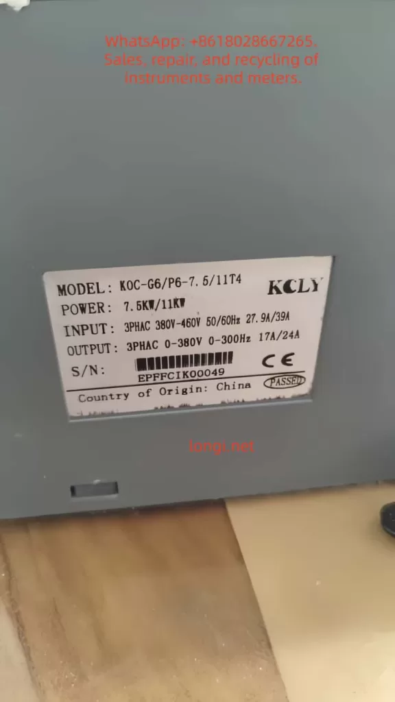
The KCLY (Kechuang Liyuan) KOC-G6/P6 series high-performance vector control inverters adopt sensorless vector control technology. They feature a starting torque of 150% rated torque at 0.35Hz and a speed stability accuracy of ±0.5%. These inverters are widely used in CNC machine tools, wire drawing machines, textile equipment, injection molding machines, hoisting equipment, and other industries. This guide is based on the official user manual and provides detailed instructions on panel operation, external terminal control, potentiometer speed regulation, fault handling, and typical application cases to help users master the equipment quickly and achieve efficient and stable operation.
1. Operation Panel Introduction
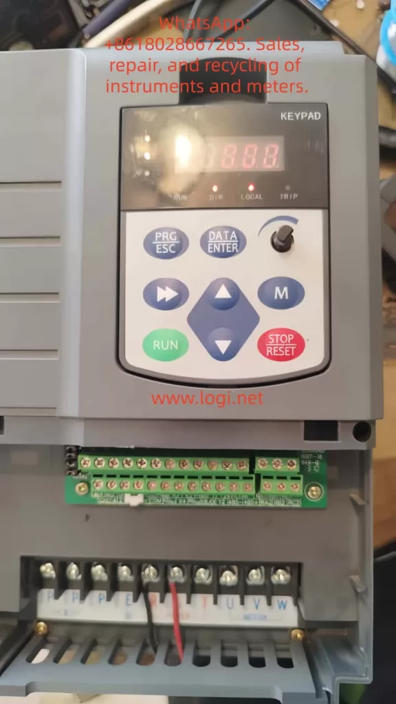
The KOC-G6/P6 series comes standard with a digital operation panel (keypad) featuring an ergonomic key layout. It supports parameter setting, operation monitoring, fault reset, and other functions. The panel mainly includes a digital display area, indicators, and keys.
Indicator Light Functions
- Hz/A/V: Frequency/Current/Voltage display (flashing indicates running).
- RUN: Running status (solid on for running, flashing for decelerating/stopping).
- DIR: Forward/Reverse indication (solid on for reverse).
- LOCAL: Local control (lights up when controlled by the panel).
- TRIP: Fault alarm.
Key Functions
- PRG/ESC: Enter/Exit menu, clear alarms.
- DATA/ENTER: Confirm modifications, enter sub-menu.
- Shift Key: Switch editing digits or monitor parameters.
- UP/DOWN: Increase/decrease values or function codes.
- M Key (Multi-function key, defined by FU.114): 0-Invalid; 1-Forward/Reverse toggle; 2-Jog operation.
- RUN: Start (valid in keypad control mode).
- STOP/RESET: Stop or reset faults (can be set to be valid in terminal/communication mode via FU.115).
Panel Operation Procedure
- After power-on, the set frequency is displayed (default 50.00Hz).
- Press PRG to enter the primary menu (mainly FU function group).
- Use UP/DOWN to select the function code, press DATA to enter edit mode, use UP/DOWN to modify the value, press DATA to confirm, and press PRG to exit.
- Quick Monitoring Mode: Press PRG to cycle through 13 operating parameters (set frequency, output frequency, current, voltage, speed, temperature, etc.).
How to Set and Cancel Password (Parameter Access Restriction)
KOC-G6/P6 provides write protection for function codes to achieve “password” level access control:
- Set Access Restriction: Enter FU.200 and set it to 1 (Valid). At this point, no parameters can be modified except for basic monitoring, protecting intellectual property and site settings.
- Cancel Password/Restriction: Change FU.200 to 0 (Invalid) to restore modifiable status.
- Operation Suggestion: Set to 0 during initial debugging, and set to 1 after debugging is complete. Combine with FU.199 initialization function for hierarchical management.
How to Restore Factory Default Parameters
- Enter function code FU.199.
- Set it to 1 (Initialize to factory defaults) and press DATA to confirm.
- The inverter automatically restores all FU group parameters (motor parameters, control mode, terminal definitions, etc.) to factory settings.
- Note: Back up key parameters before operation (using upper computer or manual recording). FU.199=2 can clear fault records separately.
After restoration, motor auto-tuning (FU.060=1 or 2) and basic parameter settings are required.
2. External Terminal Forward/Reverse Control and Potentiometer Frequency Setting
The KOC-G6/P6 supports flexible external control, suitable for automated production lines.
External Terminal Forward/Reverse Control Wiring and Parameter Settings
Wiring Key Points (Control Circuit Terminals)
- +24V and COM: Provide control power.
- X1 (or X2) connect to forward button/contact (FWD).
- X2 (or X1) connect to reverse button/contact (REV).
- COM common terminal (Note: No additional enable is required for two-wire system).
- Grounding terminal E must be reliably grounded.
Recommended Parameter Settings (FU Group)
- FU.002 (Operation Command Source) = 1 (Analog Terminal Control).
- FU.088 (Terminal Control Mode) = 0 (Two-wire Type 1, most common: X1 closed for forward, X2 closed for reverse, both closed to stop); or =1 (Two-wire Type 2: X1 forward, X2 reverse); Three-wire type (2 or 3) requires an additional enable terminal.
- FU.080 (X1 Function) = 1 (Forward Run).
- FU.081 (X2 Function) = 2 (Reverse Run).
- FU.024 (Rotation Direction Control) = 0 (Default direction).
- FU.048 (Forward/Reverse Dead Time) = 0.5s (Prevents impact from frequent switching).
Operation: External buttons control start/stop and direction, with priority higher than the keypad. Supports multi-function input expansion (X3-X8 can be set to jog, reset, etc.).
External Potentiometer Frequency Setting
Wiring
- One end of the external potentiometer (10kΩ recommended) connects to +10V, the other end to GND, and the middle tap to AI1 (voltage type 0-10V).
- For current type, switch the AI1 jumper to I position (0-20mA), but voltage type is more common.
Parameter Settings
- FU.002 = 0 (Keypad control) or 1 (Terminal control), depending on the command source.
- FU.003 (Frequency Instruction Selection A) = 2 (AI1).
- FU.089~FU.092: AI1 curve calibration (default 0-10V corresponds to 0-50Hz, max/min values can be adjusted).
- FU.093 (AI1 Filter Time) = 0.5s (Anti-interference).
- FU.005 (Frequency Source Combination) = 0 (Pure AI1) or superimposed with other sources (A+B, etc.).
Speed Regulation Effect: Rotating the potentiometer achieves smooth speed regulation from 0 to max frequency. Combined with vector control, it achieves high torque at low frequency. The panel potentiometer (FU.003=0) can be used as a backup.
Note: Analog input requires shielded cable, length <50m; ensure jumpers are correct (AI1 default is voltage).
3. Fault Codes and Troubleshooting
KOC-G6/P6 faults are queried via the TRIP light, panel display code, and FE group records. Common fault codes (based on series characteristics) and solutions:
| Fault Code | Meaning | Cause | Solution |
|---|---|---|---|
| OCx | Overcurrent | Excessive current during acceleration/operation (heavy load, short acceleration time, parameter mismatch) | Extend FU.014/015 acceleration time; check motor auto-tuning (FU.060); reduce carrier frequency (FU.022); check for mechanical jamming. |
| OUx | Overvoltage | High DC bus voltage during deceleration (short deceleration time, high inertia) | Extend deceleration time; add braking resistor (PB terminals); enable FU.052 automatic voltage stabilization. |
| LU | Undervoltage | Low input voltage or momentary power loss | Check power supply; enable FU.040 restart after momentary power loss. |
| OH | Overheat | Inverter or motor overheating | Improve heat dissipation; check air duct; reduce carrier frequency; set FU.117 motor overload factor. |
| EF | External Fault | Multi-function input triggered | Check external signals, clear after reset. |
| Others | Short Circuit/Ground/Parameter Error | SC, GF, Parameter Error, etc. | Power off and check insulation; verify parameters; contact manufacturer for serious faults. |
General Troubleshooting Steps
- Record the fault code and operating parameters (check FE group).
- Restart after powering off for 10 minutes; check wiring and insulation.
- Perform motor parameter auto-tuning.
- Enable FU.125 automatic fault reset (0-3 times).
- For serious faults, contact the manufacturer (400-788-9588).
Regular Maintenance: Check capacitors and fans; record maximum temperature.
4. Typical Application Cases
Case 1: CNC Machine Tool Spindle Control
A precision machining center uses a 7.5kW KOC-G6. Set open-loop vector control (FU.001=1), AI1 potentiometer speed regulation (180% torque at 0.35Hz), and S-curve acceleration/deceleration. Achieves low-speed precision machining with dynamic response <20ms and speed stability ±0.3%. Replaces imported brands with a 30% cost reduction.
Case 2: Wire Drawing Machine Tension Control
A medium wire drawing machine uses an 11kW P6 model. External terminal forward/reverse + multi-speed (FU.128-135) combined with PID closed-loop (FU.148=1). Operates without a dancer arm, with stable high torque at low frequency. The power-off restart function ensures continuous production with significant energy savings.
Case 3: Injection Molding Machine Energy-Saving Retrofit
A 22kW G6 with injection molding dedicated expansion card. Receives molding machine signals to automatically distribute flow and pressure. Trip-free design (200% overload capacity for 0.5s) and green output reduce interference. Measured energy saving of 20-35%; no parameter changes needed when replacing molds.
Case 4: Textile Frequency Swing and Constant Linear Speed
Chemical fiber equipment uses 15kW. Enables frequency swing function, anti-overlap, and fixed-length counting (internal counter). Constant linear speed mode prevents loose inside/tight outside. 10-hour long acceleration/deceleration time adapts to roving frames, improving yarn quality.
Case 5: Hoisting Equipment Four-Quadrant Operation
A 5.5kW crane uses torque monitoring + four-quadrant operation to prevent slipping. Speed tracking function (FU.025=2) enables recovery after momentary power loss, ensuring safety with braking unit.
5. Summary and Precautions
The KOC-G6/P6 series is renowned for high reliability (independent air duct, three-proof design, comprehensive protection) and flexibility. Correctly setting panel/terminal parameters and performing motor auto-tuning are key to stable operation. Recommendations:
- Perform insulation check and motor auto-tuning before first use.
- Back up important parameters.
- Regularly check heat dissipation and wiring.
- Consult manufacturer technical support for complex applications.