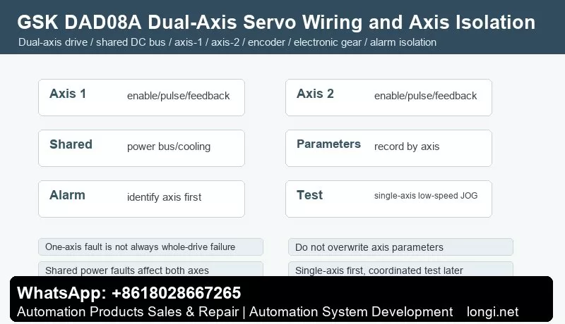
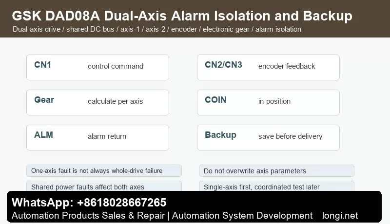
GSK DAD08A is a dual-axis servo drive used on CNC machines, feeding units and compact automation systems. Unlike single-axis DA98 drives, one drive manages two servo motors. The axes may share power bus, cooling and protection, but command signals, encoder feedback, electronic gear and tuning must be handled per axis.
Do not judge the whole drive as failed before identifying whether the alarm belongs to axis 1, axis 2 or a shared power/cooling section.
Wiring Check
Check main power, grounding, braking resistor, fan and cooling path first. Label motor cables, brake cables and encoder cables as axis 1 and axis 2. If motor or encoder plugs are swapped, one axis may run while the other alarms, or both directions become confusing.
Return ALM, SRDY and COIN signals separately to CNC or PLC whenever possible. A single common alarm makes troubleshooting slower.
Single-Axis JOG First
Do not run coordinated programs first. Move axes to a safe position, enable axis 1 only, run low-speed JOG or low-frequency pulse, then test axis 2 in the same way. Only after both axes run stably should coordinated motion be restored.
If one axis alarms, swap motor and encoder cables carefully for a short low-speed test. If the fault follows the motor, check motor and encoder. If it stays on the same channel, check the drive channel, terminals or parameters.
Electronic Gear and Parameters
Each axis may have different screw pitch, reduction ratio and mechanical direction. Calculate electronic gear separately for each axis. Use a fixed pulse test to measure actual movement. Proportional size error points to electronic gear. Bidirectional error points to backlash or coupling.
Record parameters per axis: control mode, pulse format, direction, electronic gear, speed limit, ramp time, position gain, speed gain, torque limit, in-position window and alarm output logic. Execute parameter write/save before delivery.
Alarm Isolation
Single-axis faults include encoder open circuit, Z phase error, UVW feedback error, following error, overload, direction error and in-position failure. Check the matching encoder cable, motor cable, load and axis parameters.
Shared faults include main power abnormality, DC bus over/undervoltage, cooling fault, braking resistor fault and control power fault. These usually stop both axes.
Coordinated-motion faults occur when single-axis tests are normal but synchronized motion alarms. Check controller pulse frequency, acceleration, mechanical interference and load inertia.
Delivery Flow
Record parameters and wire numbers, confirm motor/encoder matching, check shared power and cooling, JOG axis 1, JOG axis 2, set electronic gear per axis, tune gains per axis, run coordinated low-speed test, verify ALM/SRDY/COIN returns, save parameters and run full load cycle.
GSK DA98A/DA98D AC Servo Drive Manual Guide: Replacement Matching, Panel JOG, Parameter Save, Electronic Gear, Encoder and Alarm Repair
DA98A/DA98D Maintenance Focus
GSK DA98A and DA98D are later members of the DA98 AC servo drive family. They are used on CNC lathes, milling machines, grinders, feed axes and automatic positioning mechanisms. They share the same service logic as DA98, but replacement requires more attention to motor model, encoder type, firmware/version differences and EEPROM data.
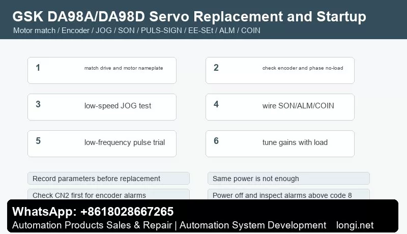
Do not replace only by power rating. Record original parameters and motor nameplate first. The common mistakes are wrong motor-encoder matching, forgetting EEPROM write after parameter changes and misjudging mechanical jam or encoder contact failure as drive failure.
Panel Startup and JOG
Before power on, check main power, grounding, U/V/W motor cable, braking resistor, CN1 control signals, CN2 encoder cable and shield. On first power up, do not enable SON immediately. Check display and alarm code first.
If there is no alarm, use JOG or low-speed trial run with the axis in a safe position. Verify direction, noise, current and encoder feedback. If the motor vibrates or alarms immediately, check phase order, encoder cable, coupling and load inertia before tuning gains.
CN1 Control Logic
CN1 usually exchanges SON enable, ALRS reset, drive inhibit, deviation clear, PULS/SIGN or dual pulse input, SRDY ready, ALM alarm and COIN in-position signals. At minimum, ALM and SRDY should return to CNC or PLC so the controller knows whether the servo is really ready.
If the axis does not move, check CNC pulse output, SON state, ALM, drive inhibit, pulse inhibit, electronic gear ratio and COIN conditions. If direction is reversed, change one location only; do not change CNC parameter, motor phase and drive direction at the same time.
CN2 Encoder and Motor Matching
CN2 carries encoder feedback. Encoder alarms, Z phase loss, UVW error and count error often come from loose connector, backed-out pin, broken shield, 5 V drop or encoder failure. Check cable and feedback first before replacing the drive.
After replacing drive or motor, confirm motor model parameter, encoder line count and feedback direction. Wrong matching may still allow JOG but cause positioning error, crawling, overcurrent or overheating.
Electronic Gear and Position Control
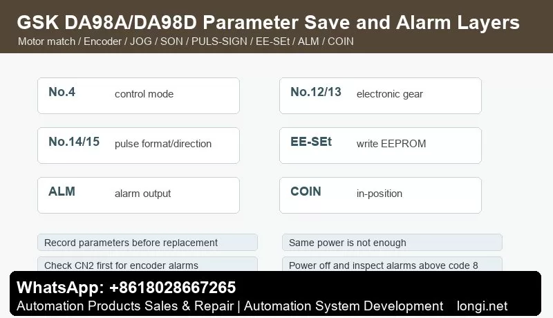
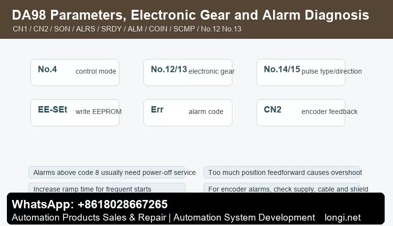
In position mode, electronic gear ratio defines mechanical movement per CNC pulse. No.12 and No.13 are commonly used as numerator and denominator, while No.14 and No.15 set pulse format and direction. Proportional size error points to electronic gear error. Bidirectional inconsistency points to backlash or mechanical issues.
Use a fixed low-frequency pulse test, measure actual movement, calculate No.12/No.13 and then verify with low-speed G01/G00 movement. Do not hide electronic gear error by changing tool offset or error window.
EEPROM Parameter Save
After changing control mode, electronic gear, pulse direction, JOG speed, speed/position gains, torque limit and related parameters, execute EE-SEt to write EEPROM. Otherwise the drive may revert after power-off.
Before replacement delivery, record control mode, pulse input type, electronic gear, maximum speed, acceleration/deceleration time, speed PI, position gain, feedforward, torque limit, alarm output logic and in-position window.
Speed Mode and Torque Limit
Some DA98A/DA98D applications use speed mode rather than pulse position mode. Check mode, speed command, forward/reverse start, maximum speed, ramp time and speed-arrival output. For torque-limit issues, check external limit input, parameter limit, load and motor current.
If no-load test is normal but load operation alarms, check guide lubrication, ball screw bearing, coupling alignment and load inertia. Parameters cannot repair a jammed machine.
Alarm Layers
Power and main-circuit alarms: check input voltage, braking resistor, DC bus capacitor, power module, contactor and grounding. Overvoltage during deceleration often relates to braking energy, inertia or too short deceleration time.
Encoder alarms: check CN2 cable, connector, shield, 5 V supply and encoder before replacing the drive.
Following error: check electronic gear ratio, command frequency, position gain, mechanical jam, backlash and inertia.
Overcurrent, overload and overheating: check motor phase cable, load jam, ramp time, speed gain, fan cooling and motor insulation. Hard alarms that cannot be cleared by ALRS require power-off inspection.
Recommended Commissioning Flow
Record original parameters and nameplates, confirm motor and encoder matching, power up without alarm, use low-speed JOG, wire CN1 basic signals, calculate electronic gear, test low-frequency pulse movement, tune gains and torque limits, execute EE-SEt and finally verify positioning accuracy under load.
GSK980TD CNC System Manual Guide: Operation Panel, Parameter Switch, PLC Diagnosis, Homing, MDI, Tool Offset, I/O and Fault Repair
What the GSK980TD Controls
GSK980TD is a lathe CNC system used on economical CNC lathes and retrofit machines. It is not only a display unit or a servo drive. It interprets machining programs, controls X/Z axis motion, handles spindle, coolant, lubrication and turret M functions, manages I/O logic, tool offsets, alarms and machine parameters.
For maintenance, judge the system as a complete chain: operation mode, parameter switch, PLC inputs and outputs, axis drive, limit switches, emergency stop, spindle control and program state. A screen without an alarm does not mean the machine is ready, and a ready servo drive does not mean the CNC conditions are satisfied.
Panel and Page Functions
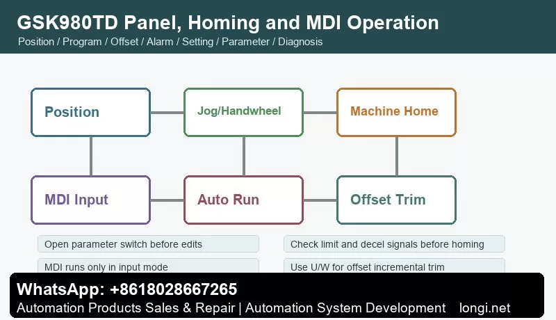
The operation panel has LCD display, edit keyboard, page keys and machine-control keys. Page keys include Position, Program, Offset, Alarm, Setting, Parameter and Diagnosis. Mode keys include Edit, Auto, MDI Input, Manual, Handwheel/Step, Program Zero Return and Machine Zero Return.
The practical diagnostic order is: check Alarm page, check Diagnosis page for I/O, confirm key parameters, observe axis status on Position page, then use Manual or MDI for low-risk movement. Direct cycle start before checking these pages can turn a simple limit or offset issue into a crash.
Parameter Switch, Password and Electronic Disk
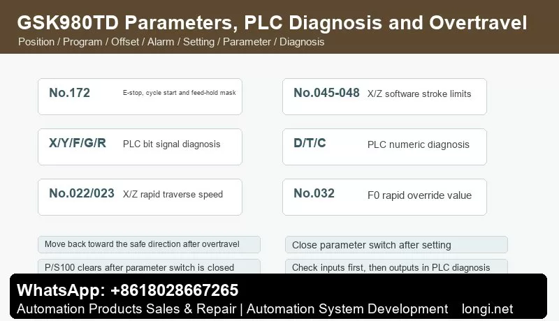
The Setting page includes parameter switch and program switch. When the parameter switch is off, system parameters cannot be modified. When it is turned on, P/S100 may appear. After setting parameters, turn the switch off again; the alarm normally clears or can be reset. Always close the parameter switch after service.
GSK980TD uses multiple password levels: system debugging, system configuration, machine builder, workshop management and operator. Low-level users cannot edit protected O9000-O9999 programs. Use the password page when protected parameters or builder programs must be modified.
The electronic disk stores state parameters, data parameters, pitch compensation and tool offsets. N0 stores factory original data, N2 servo original data, N3 stepper original data, N4 common data and N1 user data. Before large adjustments, back up working parameters to N1 or to a PC.
I/O and PLC Diagnosis
The Diagnosis page shows keyboard diagnosis, status diagnosis, PLC signal status and PLC numeric diagnosis. PLC bit signals include X0000-X0029, Y0000-Y0019, F0000-F0255, G0000-G0255, A0000-A0024, K0000-K0039 and R0000-R0999. Numeric diagnosis includes D0000-D0999, T0000-T0099 and C0000-C0099.
Use the rule: input before output, safety chain before action chain, diagnosis before rewiring. If cycle start fails, check emergency stop, feed hold, auto mode, program selection and cycle-start input first. If coolant does not work, check the internal PLC signal before checking relay output. If turret does not index, check output, in-position input and turret power.
Emergency stop can be masked by state parameter No.172 Bit3 (MESP), and external E-stop can be checked by diagnostic No.001 Bit4 (*ESP). Do not leave E-stop or limit switches bypassed after testing.
Manual, Handwheel and Homing
Manual mode supports X/Z jogging, rapid traverse, spindle control, coolant, lubrication and turret operation. Data parameters No.022 and No.023 set X/Z rapid speeds. No.032 sets the F0 rapid override. After repair, use low rapid override first and verify direction, limit switches and mechanical clearance.
Handwheel/step mode is selected by state parameter No.001 Bit3. Select X or Z axis and choose handwheel magnification. The manual warns that handwheel rotation should be below 5 revolutions per second; otherwise actual movement may not match scale marks.
Zero return includes program zero return and machine zero return. Machine zero return depends on the installed deceleration switch, one-revolution signal or Hall switch. If the machine has no reference switch, do not use machine zero return. Check return direction, decel switch, limit switch, servo ready and E-stop before homing.
MDI and Automatic Run
MDI can run one command block, such as G50, G00, G01, M03, M05, M08, M09, S and T commands. MDI runs only in input mode. Use it to test spindle, coolant, turret and short low-speed movement, but do not treat MDI as a full replacement for dry run and single-block verification.
Before automatic running, confirm the program, current coordinate, work offset, tool offset, spindle state and modal G/M/S/T conditions. When starting from a middle block, use MDI to restore required modal states first.
Tool Offset and Tool Setting
The Offset page modifies X/Z offset values. Absolute input uses X or Z. Incremental trim uses U or W. For example, input U0.001 to increase X offset by 0.001 mm. When the origin of an offset is unclear, avoid rewriting absolute X/Z values; use small U/W trims and record before/after values.
GSK980TD supports fixed-point tool setting, trial-cut tool setting, machine-zero tool setting and tool setting with compensation. Tool setting with compensation requires state parameter No.005 Bit1 (PPD). Direct measured offset input depends on state parameter No.012 Bit5 (DOFSI).
Common G Codes and Auxiliary Functions
Common lathe commands include G00 rapid positioning, G01 linear interpolation and G50 coordinate setting. Common M functions include M03 spindle forward, M04 spindle reverse, M05 spindle stop, M08 coolant on and M09 coolant off. Actual spindle speed display requires a spindle encoder.
If M03 is issued but the spindle does not rotate, separate CNC M-output, spindle inverter/servo enable, analog command, forward/reverse terminals and spindle override. If only speed display is missing, check spindle encoder feedback and related parameters.
Overtravel and Safety Alarms
GSK980TD uses hardware overtravel switches and software stroke limits. Software travel range is set by data parameters No.045, No.046, No.047 and No.048 for X/Z positive and negative limits. After overtravel, move manually toward the safe direction, then press reset. Do not permanently disable software limits or short hardware limit switches.
After E-stop release, spindle, coolant and lubrication usually need to be restarted. If axes still cannot move, check not-ready alarm, *ESP signal, servo ready, limit state and selected operation mode.
Fault Handling Checklist
P/S100 alarm: usually related to open parameter switch. Close the switch, reset and power cycle if necessary.
Cycle start invalid: check auto mode, selected program, E-stop, feed hold, cycle-start input and PLC condition.
Axis does not move or direction is wrong: check mode, servo ready, enable, limits, homing status, direction parameters, servo alarm and command output.
Tool offset ineffective or size error: check offset number, T command, X/Z versus U/W input, work coordinate, machine zero return, backlash and pitch compensation.
Spindle does not rotate or speed is wrong: check M03/M04/M05 output, spindle override, analog or switch speed mode, spindle encoder and inverter or spindle servo parameters.
Coolant, lubrication or turret does not work: check PLC internal signal, Y output, relay, fuse, contactor and load. For turret faults, also check in-position signal and tool-number feedback.
The most reliable workflow is: use Alarm page to classify the fault, Diagnosis page to verify signals, Parameter page to check configuration, Manual/MDI to test safely, then Auto mode for final dry run and cutting verification.
GSK DA98 AC Servo Drive Manual Guide: CN1/CN2 Wiring, Position Pulse Control, Speed Control, Electronic Gear Ratio, EEPROM Write and Alarm Repair
DA98 Is a Classic Digital AC Servo for CNC Retrofits
GSK DA98 is an early full-digital AC servo drive widely used on CNC machines, printing machinery, textile machinery and automation lines. Compared with a stepper system, DA98 uses encoder feedback from the servo motor and forms a semi-closed loop inside the drive.
For service work, do not only ask whether the motor rotates. Check control mode, CN1 command signals, CN2 encoder feedback, electronic gear ratio, gains and alarm output together. In position mode the CNC sends pulse and direction; in speed mode DA98 uses speed selection or speed command; in both modes SON enable and encoder feedback are essential.
Installation and Wiring Checks
The manual notes that DA98 default parameters may match only specific STZ motors. If another motor is used, factory parameters may be stored in the EEPROM backup area. Do not restore default parameters blindly. Confirm drive model, motor model and parameter No.1 first.
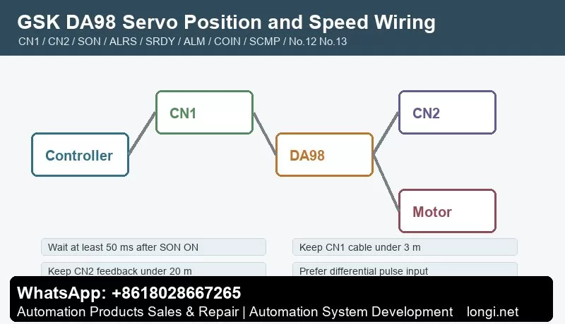
Before wiring or inspection, cut power and wait at least five minutes. Use proper grounding. Keep CN1 control cable under 3 m and CN2 feedback cable under 20 m. Use shielded cable, connect shield to FG and keep signal cables away from motor power cable, contactor coils and braking circuits.
Commission in layers. First power, motor and encoder. Then enable SON and wait at least 50 ms before command input. Then connect SRDY and ALM to CNC or PLC. Finally test PULS/SIGN, COIN, SCMP, limits and torque-limit inputs. ALRS cannot clear all alarms; alarms above code 8 normally require power-off service.
CN2 Encoder Feedback
CN2 carries motor encoder supply and A/B/Z/U/V/W signals. The manual describes a 2500-line encoder, internally multiplied to 10000 pulses per revolution. Encoder supply, shield, pin order and cable length strongly affect stability.
For encoder alarms, do not change gains first. Check 5 V supply, cable length, A/B/Z/U/V/W wiring, shield and connector. Z-pulse loss, UVW error, encoder count error and zero-point error usually point to cable, connector, encoder or drive-interface problems.
Position Pulse Control
DA98 accepts position command pulses through CN1. Supported pulse formats include pulse plus direction, CCW/CW pulse train and two-phase quadrature pulse. Parameter No.14 sets pulse input format and No.15 reverses command direction. Differential pulse input is preferred; single-ended input lowers noise immunity and allowable frequency.
If axis direction is wrong, decide whether the cause is CNC direction, No.15, motor phase or mechanics. Do not change several places at once. If the axis does not respond, check INH, SON, FSTP/RSTP, ALM and whether PULS/SIGN actually reaches CN1.
Electronic Gear Ratio: No.12 and No.13
No.12 is the position command pulse division numerator. No.13 is the denominator. Together they define the electronic gear ratio. Because a 2500-line encoder becomes 10000 feedback pulses per revolution after four-times counting, the ratio must account for encoder pulses, screw pitch, reduction ratio and CNC pulses per millimeter.
Proportional size error usually means electronic gear error. Bidirectional repeatability error points more to backlash, coupling, encoder feedback or gain setting.
Speed Mode and Internal Speeds
Set No.4 to speed mode when DA98 is used as a speed servo. Internal speeds are selected through SC1/SC2 and parameters such as No.24-No.27. SCMP speed-arrival output can be used by PLC. JOG speed is set by No.21 and is useful for no-load testing.
If speed mode does not run, check No.4, SON, ALM, SC1/SC2, speed parameters, FSTP/RSTP, torque limit and maximum speed No.23. If no-load operation is normal but load operation alarms, check load inertia, ramp time No.7 and torque limits No.34-No.37.
Gain Tuning
Tune speed loop first, then position loop. Higher speed proportional gain improves stiffness but can cause vibration. Higher position proportional gain reduces following error but can cause overshoot. Position feedforward is normally set to zero unless high response is required; excessive feedforward can destabilize the position loop.
Frequent starts, large inertia and short ramp time can cause overheating or overvoltage. Start with conservative ramp time, then improve response gradually.
EEPROM Parameter Write
Parameter edits are in memory until written. EE-SEt writes memory parameters into EEPROM. Select EE-SEt, press and hold Enter for more than three seconds, wait for StArt and then FInISH. EE-dEF restores defaults, but use it only after confirming drive model No.1.
Before delivery, record No.1, No.4, No.7, No.9, No.10, No.12, No.13, No.14, No.15, No.20, No.21, No.23 and No.34-No.37.
Alarm Diagnosis
Main-circuit overvoltage: usually caused by fast deceleration, high inertia, braking problem or power abnormality. Increase No.7 and check load.
Encoder faults: check CN2 supply, cable, shield, pin order, encoder and interface circuit. Long cable can reduce encoder supply voltage.
Following error: check electronic gear ratio, pulse frequency, position gain and mechanical jam. Do not only enlarge the error window.
Vibration with alarm: check coupling, inertia, speed gain, position gain and encoder cable before replacing the drive.
Reset invalid: alarms above code 8 usually cannot be cleared only by ALRS; power-off inspection is required.
The reliable DA98 workflow is: confirm motor and drive model, wire TB/CN1/CN2, set No.4 mode, calculate No.12/No.13 electronic gear, run no-load JOG, test low-speed pulse motion, tune speed and position loop, execute EE-SEt, then verify under load.
GSK GS3000Y and GS4000Y AC Spindle Servo Unit Manual Guide: Panel Operation, CN1/CN2/CN3 Wiring, Parameter Management, Spindle Orientation, Cs Axis and Fault Diagnosis
Treat GS3000Y/GS4000Y as a Spindle Process Unit
GSK GS3000Y and GS4000Y AC spindle servo units are used on CNC lathes, machining centers and automation equipment. They support constant-power speed control, spindle orientation and Cs-axis position control. They should not be commissioned like ordinary inverters.
A spindle servo system must coordinate speed, position feedback, braking, orientation, clamp interlock and CNC machining sequence. M03 requires speed arrival before feed; tool change requires orientation; rigid tapping or Cs-axis control requires position mode; chuck and tool-clamp signals must be part of PLC interlocks. Commission the unit in the order of wiring, feedback, parameter management, speed operation, orientation/Cs axis and fault diagnosis.
Model and Interface: GS-N Versus GS-C
The manual separates GS-N and GS-C types. GS-N uses D-SUB connectors, usually with incremental encoder motors and no GSK-CAN bus. GS-C uses MDR connectors, supports absolute encoder motors and includes GSK-CAN. Feedback codes are also important: P is for incremental encoder, A/B for absolute encoder, 1 for CN2 motor feedback only, and 2 for both CN2 motor feedback and CN3 second feedback.
When replacing a drive, do not check only power rating. Confirm voltage class, output current, motor type, encoder type, CN2/CN3 configuration, second-feedback requirement and CNC interface. A mismatched encoder interface can power on normally but fail in orientation or position control.
Power Wiring, Brake Resistor and Safety
Install proper breaker, contactor, grounding, shield treatment, reactors or filters as required. Check input power, U/V/W motor output, brake resistor, PE grounding and cable shielding. If Err-27 appears during running, the manual points to checking motor phase sequence and swapping two phases where appropriate.
Brake resistors can remain hot and charged after operation. Wait before touching. Frequent spindle acceleration and deceleration requires correct braking capacity. Undersized or open brake resistor can cause overvoltage, long stopping distance or repeated alarms.
Panel and Status Monitoring
The panel uses keys for parameter number, value editing, shift and confirmation. The manual notes that the decimal point on the display indicates whether an edited parameter has been confirmed. If you exit without confirmation, the setting is invalid.
Menus include status monitoring, parameter setting, parameter management, manual run and jog run. PA3 selects the initial monitor state. Useful monitor items include motor speed, current position, position command, following error, motor current, analog speed command, speed command, pulse command frequency, torque, heatsink temperature, motor temperature, DC bus voltage, alarm display, input status and output status.
PA0, PA1 and EEPROM Parameter Management
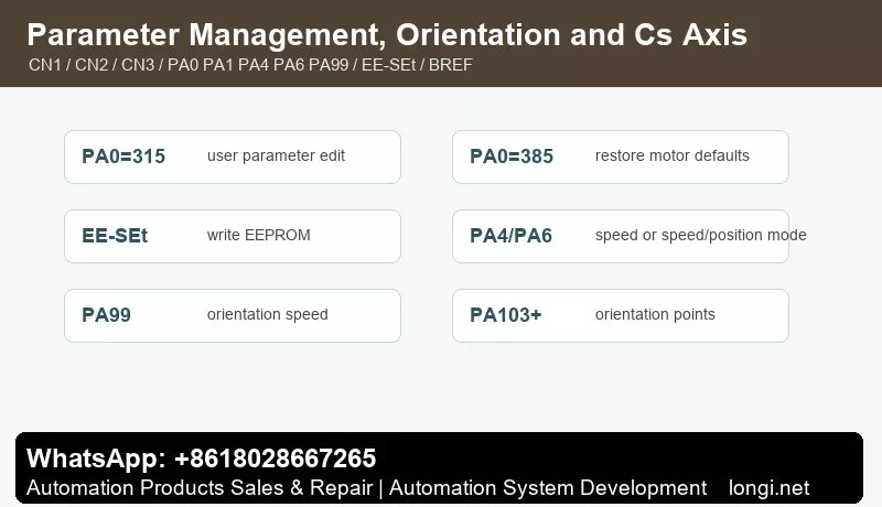
The manual clearly states that PA0=315 is the user parameter modification password. At each power-on, PA0 returns to 315. PA0=385 is used to restore motor default parameters and allows PA1/PA2 editing. PA1 is the motor model code.
EE-SEt writes memory parameters into the EEPROM parameter area. EE-rd reads EEPROM parameters back into memory. EE-bA writes current parameters into the backup area. If a parameter works today but disappears after power cycling, EE-SEt was probably not executed. After final commissioning, execute EE-SEt, then use EE-bA for backup and verify after power cycling.
CN1 Control Signals
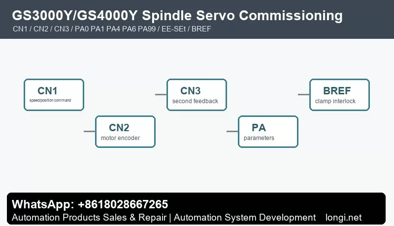
CN1 carries the key interface between CNC and spindle servo: analog speed command, pulse position command, enable, forward/reverse, reset, orientation start, clamp interlock, speed arrival, zero speed, alarm output and position output.
Wire and test in layers. First power and encoder, then enable and alarm output, then speed command and direction, then orientation, speed arrival, zero speed, BREF clamp interlock and position outputs. Do not wire every CN1 signal at once during retrofit; otherwise command faults, feedback faults and PLC interlocks are hard to separate.
The manual appendix gives examples for GSK980TDc and GSK988T. For speed control with orientation, typical settings include PA4=1, PA6=1 for external 0-10 V analog command, PA51 for analog-speed direction reversal, PA99 orientation speed, and PA103/PA105/PA107/PA109 orientation positions. For speed/position Cs-axis control, typical settings include PA4=3, PA5 position-command mode, PA28 position direction and PA90 switching reference.
CN2/CN3 Encoder Feedback
CN2 is motor encoder feedback. CN3 is used on selected GS-N/GS-C configurations for second-position feedback. Speed mode can run with stable speed feedback, but orientation and Cs-axis control require reliable position feedback.
Check encoder type, connector, shield, supply, PA3 position monitor and actual spindle movement. Orientation position should be set from real monitor values, not guessed. With high-resolution magnetic or magnetic-grid encoders, pay attention to high/low position display.
Speed Mode, Orientation and Cs Axis
For external analog speed mode, confirm PA6, analog polarity, 0-10 V range, common terminal, shielding and PA51 direction. Speed arrival must be real; do not short it only to make the CNC continue.
Orientation is used for tool change, fixed spindle position and rigid tapping preparation. PA99 sets orientation speed and PA103-series parameters define orientation positions. If orientation fails, check encoder zero, orientation position, braking mode and mechanical backlash before changing gains.
Cs-axis control treats the spindle as a position axis. Use PA4=3 and configure PA5, PA28 and PA90 according to the CNC system. First test small low-speed angles, then check electronic gear ratio, position arrival and repeatability.
BREF Clamp Interlock and PLC Safety Chain
BREF spindle clamp interlock is important. The spindle should not release the tool before zero speed; it should not start before the tool is clamped; it should not feed before speed arrival or orientation completion. PLC logic should include speed arrival, zero speed, orientation complete, clamp complete, alarm output and emergency stop.
Shorting BREF or speed-arrival signals may keep production moving for a moment, but it increases tool-change and machining risk. Diagnose which interlock condition is missing instead.
Fault Diagnosis
Speed mode does not run: check enable, run command, analog speed command, PA6, PA51, emergency stop, alarm output, input-terminal status and motor wiring.
Wrong direction: check U/V/W, PA51, PA28 and CNC direction signal.
Orientation drift: check CN2/CN3 encoder, shield grounding, coupling, orientation position parameters, braking mode and spindle backlash.
Parameters lost after power-off: execute EE-SEt and then EE-bA after final tuning.
Overvoltage during deceleration: check brake resistor, wiring, heat dissipation, deceleration time and spindle inertia.
Position mode following error: check PA4, PA5, PA28, PA90, electronic gear ratio, encoder feedback and CNC position command.
The practical rule is simple: confirm model and feedback first, use PA0/PA1 to load correct motor parameters, save with EE-SEt, verify CN1 commands and interlocks, rely on CN2/CN3 for orientation and Cs-axis feedback, then diagnose alarms by layer.
GSK GR-L Bus-Type AC Servo Drive Manual Guide: GSK-Link Setup, CN2/CN3 Feedback, PA Parameters, Electronic Gear Ratio, Servo Tuning and AL Alarm Diagnosis
GR-L Is a CNC Bus Servo Axis System
GSK GR-L is not just a pulse servo drive with fewer wires. It is a bus-type AC servo drive unit for CNC machine tools. The important manual topics are GSK-Link, real-time CNC communication, CN2/CN3 feedback, PA parameters, inertia identification, resonance suppression, position control, speed control and torque control.
During commissioning, do not only check whether the drive powers on or whether the motor jogs. A stable axis depends on the CNC, GSK-Link network, drive unit, motor, encoder, mechanical load and PLC diagnosis working as one closed-loop system. Fewer bus wires do not mean easier commissioning; many checks move into the CNC diagnosis screen and parameter system.
Model, Capacity and Feedback Interface
Before replacing a GR-L drive, confirm voltage class, capacity, communication interface, encoder protocol and feedback interface quantity. The manual describes CN2 and CN3 feedback interfaces and support for absolute encoders, incremental encoders, Tamagawa, BISS and EnDat2.2 protocols. Some versions use only CN2 motor feedback, while others also provide CN3 second-position feedback.
A wrong feedback interface can allow the drive to power on but still cause encoder alarms, position feedback errors, orientation failure or a bus axis that cannot be enabled. For spindle or electric-spindle applications, also confirm encoder tooth count and related feedback parameters such as PA200 where applicable.
Power Circuit, Brake and Grounding
GR-L is still a servo power unit. Input power, motor output, brake resistor, PE grounding, shielding, reactors and filters must be checked before tuning. Bus communication does not remove electrical noise. In fact, bus communication, encoder feedback and PWM motor output exist together, so wiring quality is critical.
Keep motor power cable, encoder cable and GSK-Link communication cable separated. Check brake resistor value and power rating, especially on heavy axes and spindles with frequent deceleration. Do not try to solve a wiring, grounding or braking problem by reducing servo gains.
GSK-Link Online Check
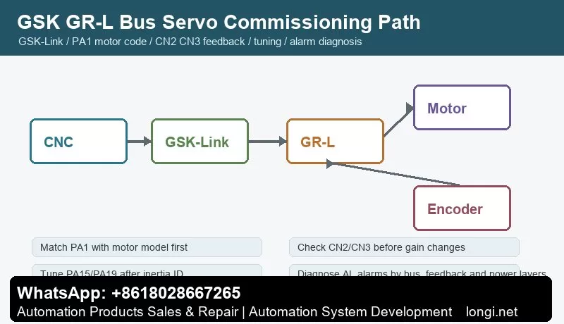
Commission the bus in three steps: confirm physical bus wiring, confirm that CNC recognizes the axis, and confirm that drive status matches CNC diagnosis. If the CNC cannot identify the servo axis, electronic gear ratio and gain tuning are meaningless.
Check station number, axis number, cable direction, termination, CNC parameters and drive state. On multi-axis machines, bring axes online one by one. This avoids mixing duplicated station numbers, cable breaks, wrong axis parameters and mechanical problems.
Panel Operation and PA Parameters
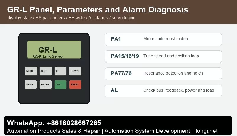
The GR-L panel is used for status display, parameter viewing, parameter editing, alarm reset and commissioning. The first key parameter is PA1, the motor model code. The manual requires selecting the motor model code and loading default motor parameters. If PA1 is wrong, current loop, speed loop, encoder setup, rated current and protection thresholds can all be wrong.
After changing important parameters, execute the required save/write operation and verify after power cycling. Record at least PA1, feedback type, second feedback configuration, electronic gear ratio, speed loop, position loop, braking, limit, alarm output and bus-axis parameters.
CN2 and CN3 Feedback
CN2 is normally motor feedback. CN3 can be used for second-position feedback such as linear scale, second spindle encoder or mechanical-end feedback. Feedback faults should be diagnosed in three layers: electrical layer, protocol layer and mechanical layer.
The electrical layer includes connector, shield, supply, cable and pin definition. The protocol layer includes encoder type, communication protocol, resolution and PA parameter match. The mechanical layer includes encoder mounting, coupling slip, scale contamination and backlash. If feedback is unreliable, gain tuning only hides the real problem.
Electronic Gear Ratio
Electronic gear ratio maps CNC command units to motor rotation, screw pitch, reduction ratio or table movement. It is not merely a speed amplifier. It directly affects command resolution, positioning accuracy, following error and machining size.
Before setting the ratio, list CNC command unit, encoder resolution, screw pitch or rotary-axis angle, gear ratio and whether second feedback is used. Start with very small low-speed motion, confirm direction, then test 1 mm, 10 mm and reverse repeatability. Proportional size error usually points to electronic gear or mechanical ratio; large bidirectional error points to backlash or feedback problems.
Inertia Identification and Servo Gain Tuning
The manual separates basic performance tuning, inertia identification, speed loop, position loop and resonance suppression. The practical sequence is: confirm motor and feedback, perform inertia identification, tune speed loop, then tune position loop.
Parameters such as PA15, PA16, PA18, PA19 and PA23 relate to speed-loop and position-loop behavior. Speed gain too low causes slow response and large contour error; too high causes noise, vibration or overshoot. Position gain too low causes following error; too high causes oscillation if the machine lacks stiffness.
For multi-axis interpolation, keep dynamic response consistent between axes. The manual notes that PA19 should be handled consistently or conservatively after tuning multiple axes. Before inertia identification, ensure there is no active alarm or warning such as AL-603 and that travel is safe.
Resonance Suppression
Machine-axis screaming, vibration or surface marks at certain speed ranges can be mechanical resonance. The manual mentions real-time resonance detection and parameters such as PA77 and PA76. The idea is to detect the resonance frequency, write it into notch parameters, and adjust notch width and depth carefully.
Do not treat every vibration as resonance. Loose encoder coupling, poor bearings, dry guideways, wrong feedback direction or excessive gain can also cause vibration. Real-time detection is a commissioning tool; after identifying the frequency, save the correct notch setting and return the drive to a stable run configuration.
AL Alarm Diagnosis
Communication alarms: check GSK-Link cable, station number, axis number, termination, CNC parameters, power-on sequence and emergency stop state.
Feedback alarms: check CN2/CN3 connectors, encoder supply, shielding, protocol type, PA parameters and mechanical mounting.
Overcurrent, overload or overvoltage: check motor cable, brake resistor, mechanical jam, acceleration/deceleration time, load inertia and motor capacity.
Following error or position abnormality: check electronic gear ratio, position gain, limit signals, backlash, second-feedback direction and CNC axis parameters. Do not simply enlarge the following-error window.
Tuning warnings: clear alarms and interlocks first, confirm safe travel, then run inertia identification or resonance detection.
Commissioning Records
Before delivery, keep records of drive model, motor model, encoder type, CN2/CN3 usage, PA1, electronic gear ratio, loop gains, resonance parameters, brake settings, GSK-Link station/axis number, CNC axis parameters, PLC interlocks and alarm history.
Final testing should include jog, rapid move, homing, reverse repeatability, emergency stop, limit, servo alarm, power-cycle retention, continuous temperature rise and trial cutting. A stable GR-L servo system is not just a motor that rotates; it is an axis that the CNC can identify, the bus can maintain, feedback can prove, parameters can be traced and alarms can be diagnosed.
GSK DAP03 Spindle Servo Manual Guide: Panel Operation, CN1 CN2 CN3 Wiring, Speed and Position Control, Electronic Gear Ratio, Parameter Write and Alarm Handling
DAP03 Must Be Commissioned as a Closed-Loop Spindle Servo
GSK DAP03, DAY3025 and DAY3100 are spindle servo drive units. Their manual is not only about start and stop. It focuses on spindle motor control, encoder feedback, speed/position mode, CNC interface, parameter management, orientation and alarm handling.
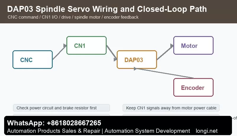
Compared with a normal inverter, a spindle servo must care about encoder feedback, position arrival, speed arrival, electronic gear ratio, spindle orientation, braking stop and CNC machining sequence. If CNC command, CN1 control I/O, DAP03 drive, spindle motor or CN2/CN3 feedback is wrong, the drive may power on but will not run reliably.
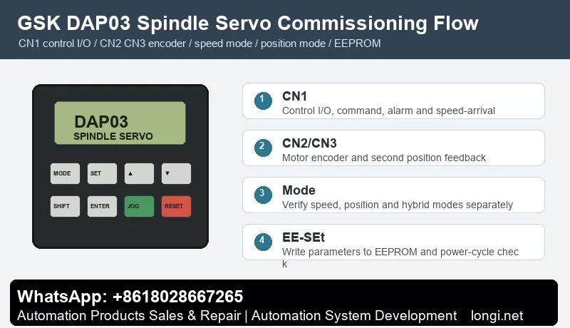
This guide follows a field-service route: panel operation, power wiring, CN1 control signals, CN2/CN3 feedback, speed mode, position mode, electronic gear ratio, EEPROM parameter write and alarm diagnosis.
Panel Operation and Parameter Management
The DAP03 panel is used for status display, parameter selection, value editing, manual run, jog run, alarm reset and parameter management. Always read status before changing parameters. The manual separates status monitor, parameter setting and parameter management because temporary changes and permanent storage are different operations.
The manual describes EE-SEt as the operation that writes parameters from memory into the EEPROM parameter area. If a user changes a parameter but does not execute parameter write, the value may be lost at the next power-on. In the field, many “it was adjusted yesterday but failed today” cases are caused by missing EEPROM write or missing power-cycle verification.
After initialization, Err-24 may appear if CN3 is not connected to a second position encoder, and Err-5 may appear if the temperature sensor signal on CN2 is not connected. Do not replace the control board first. Check the actual hardware configuration and set the related parameters, such as PA66 and PA73, according to the application, then execute parameter write.
Power Circuit, Brake Resistor and Grounding
Before wiring, verify voltage class, drive capacity, spindle motor model, brake resistor, breaker, contactor and AC reactor. The manual includes peripheral equipment selection for protective devices and reactors, which shows that power-circuit protection is part of the drive system.
Check three points in the main circuit: input and motor output must not be reversed, the brake resistor must match the drive capacity, and PE/shield grounding must be reliable. Spindle acceleration and deceleration can regenerate significant energy. A wrong or undersized brake resistor can cause overvoltage, unstable stop or long stopping distance.
Encoder cable, CN1 control cable and motor power cable should be routed separately. Poor shielding can cause speed fluctuation, orientation failure, position deviation or feedback alarms. On retrofit machines, encoder cables should be separated from contactor coils and motor cables whenever possible.
CN1 Control Signals
The manual lists CN1 pin definition, input signals and output signals. CN1 is the key interface between CNC and spindle drive. Common signals include servo enable, forward/reverse, command input, alarm output, speed arrival, zero speed, position complete, reset and common terminal.
Do not wire every signal at once during commissioning. First connect enable and alarm output, then confirm CNC receives the drive-ready state. Next test forward/reverse or run command. Then connect speed or position command. Finally connect speed arrival, zero speed and orientation-complete feedback. A spindle running on the drive panel does not mean the CNC has received speed-arrival or position-complete feedback.
When used with GSK 218M, GSK 980TDa, GSK 980TD1 or GSK 983M, the appendix wiring examples are useful references. Still, the final wiring should follow the actual machine schematic. Pay attention to common terminals, signal polarity, alarm contact type, command type and reset pulse duration.
CN2 and CN3 Feedback Signals
The manual treats feedback wiring as a separate topic. CN2 and CN3 are related to motor encoder and second position feedback. A spindle servo is a closed-loop system; feedback disconnection, wrong signal type, poor shielding or loose connector can cause unstable speed, failed orientation, position error or alarms.
If the machine has no second position encoder but the function is enabled, Err-24 can occur after initialization. Confirm whether CN3 feedback really exists before changing hardware. If CN2 temperature or encoder-related signals are missing, the drive can also alarm. A good check sequence is: connector, shield, encoder supply, signal waveform and parameter configuration.
Feedback problems often appear only at high speed, during orientation or during rapid acceleration. Do not reduce speed-loop or position-loop gains blindly. Check encoder installation, coupling, cable shielding, grounding and CN2/CN3 connector first.
Speed Mode Commissioning
DAP03 supports speed operation mode. The manual lists analog voltage command and internal digital command. Speed mode is usually used when CNC sends spindle speed. For analog reference, confirm voltage range, direction logic, zero drift, shield and speed scaling. For internal digital command, confirm command value, run source and ramp time.
A practical test sequence is: reduce maximum speed or disconnect risky mechanical load, observe whether the speed command changes on the drive, test low-speed forward and reverse, and then increase speed while observing current, vibration, noise and temperature. If command is zero but the spindle creeps, check analog zero drift, common terminal and zero-speed clamp.
Speed-arrival feedback is important for machining sequence. If CNC sends M03 and the PLC waits for speed arrival, the program may stop if this feedback is missing. If speed-arrival is shorted falsely, feed may begin before the spindle reaches real speed.
Position Mode and Electronic Gear Ratio
The manual includes position mode, speed/position mixed mode and electronic gear ratio for position command. Position mode is used for spindle orientation, rigid tapping, tool-change positioning and angular control.
Before setting electronic gear ratio, confirm four values: CNC command pulses per revolution, encoder feedback pulses per revolution, motor-to-spindle mechanical ratio and whether belt or gear transmission is used. A wrong gear ratio causes orientation offset, inaccurate tapping pitch, repeated position drift or cumulative error.
For the first position-mode test, command only a small pulse distance and observe direction and angle. After direction is correct, verify one revolution, half revolution, orientation position and repeatability. If position arrival is unstable, check electronic gear ratio, position-arrival window, encoder feedback and mechanical backlash before tuning gains.
Brake Stop, Orientation and Interlocks
A spindle servo must not only rotate; it must stop and orient according to process requirements. The function section of the manual covers brake stop, motor direction switching, position arrival, speed arrival, zero speed and orientation. On machining centers and CNC lathes, spindle orientation is often tied to tool change, chuck, tailstock and hydraulic clamping logic.
For brake-stop faults, distinguish electrical braking, resistor braking and mechanical braking. Too short deceleration time, undersized brake resistor or high spindle inertia can cause overvoltage or unstable stop. For orientation failure, check orientation command, position feedback, electronic gear ratio, arrival window and mechanical backlash.
Do not bypass clamping and zero-speed interlocks. The PLC should link speed arrival, zero speed, orientation complete, alarm, clamp confirmation and tool-change conditions into a safe sequence.
Alarm Handling
Err-5 temperature or sensor-related alarm: after initialization or motor replacement, check CN2 temperature signal and related parameters such as PA73 before replacing hardware.
Err-24 second position feedback alarm: if CN3 is not connected but the function is enabled, check configuration such as PA66. If second feedback exists, inspect encoder supply, shield, signal and mechanical mounting.
No rotation in speed mode: check enable, run command, direction, speed command, analog common, E-stop and alarm reset.
Positioning error in position mode: verify electronic gear ratio, feedback pulses, mechanical ratio, direction, arrival window and backlash.
Alarm immediately after run command: check motor power cable, encoder cable, brake resistor, mechanical binding, ramp time and load inertia.
Parameters lost after power cycle: confirm EE-SEt parameter write and verify again after power-off and restart.
Delivery Checklist
Backup: speed mode, position mode, electronic gear, encoder, brake and alarm parameters.
Wiring record: CN1, CN2, CN3, power circuit, brake resistor and shield grounding.
Function test: low-speed forward/reverse, speed arrival, zero speed, orientation, position complete, alarm output and reset.
Safety interlock: no feed before speed arrival, no unclamp before zero speed, no start before alarm reset.
Final check: execute parameter write, power cycle and verify critical actions again.
The core of DAP03 commissioning is simple: make feedback reliable first, stabilize speed mode second, make position mode accurate third, then connect speed arrival, zero speed, orientation and PLC interlocks into the machine sequence.