Introduction
Laser technology has become one of the most important technologies in modern industrial manufacturing, scientific research, precision measurement, and automated inspection systems. With the continuous improvement of measurement accuracy requirements, traditional laser sources with small beam diameters are often unable to meet the requirements of long-distance transmission, large-area measurement, and high-precision optical detection. Therefore, an important optical component called a laser beam expander has been widely adopted in various laser systems.
Although a laser beam expander may appear to be a simple optical accessory, it plays a critical role in controlling and improving laser beam characteristics. It can enlarge the laser beam diameter, reduce beam divergence, improve beam collimation, and optimize optical performance for different applications.
In industrial laser measurement equipment, such as laser diameter gauges, optical micrometers, and dimensional inspection systems, beam expanders are commonly installed at the laser emission side. By expanding the laser beam, they create a larger and more stable measurement field, improving measurement accuracy and system reliability.
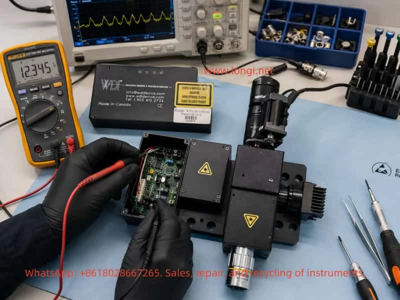
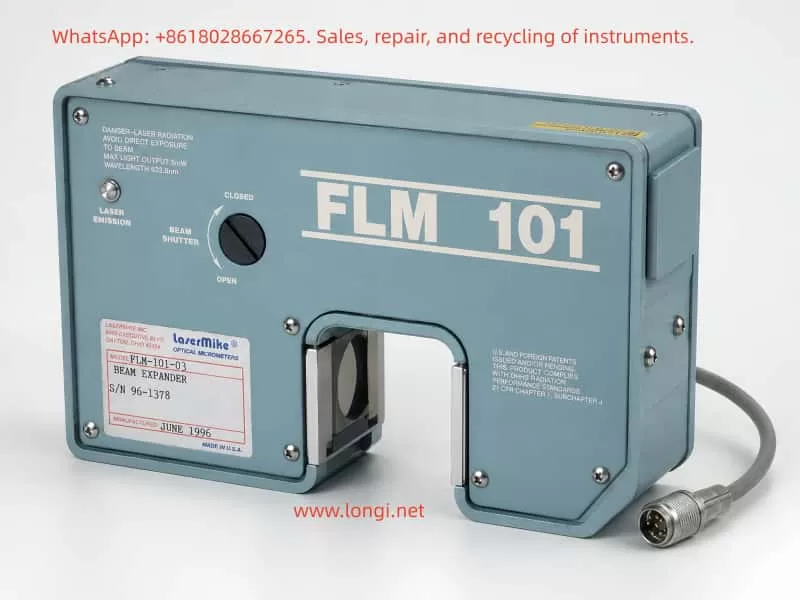
A typical example is the LaserMike FLM series beam expander, which is used as an optical component in industrial measurement systems. Some models not only contain precision optical lenses but also integrate electronic control circuits, beam shutters, electromagnetic actuators, and feedback mechanisms.
This article provides a comprehensive introduction to laser beam expanders, including:
- Operating principles
- Optical structure
- Mechanical and electronic design
- Main functions
- Industrial applications
- Proper usage methods
- Common failures
- Testing and troubleshooting procedures
It is intended for engineers, technicians, equipment maintenance personnel, and anyone interested in industrial laser systems.
1. What Is a Laser Beam Expander?
A laser beam expander, also known as a beam enlarger or laser beam expansion system, is an optical device designed to increase the diameter of a laser beam while reducing its divergence angle.
Simply speaking, it transforms:
Small diameter laser beam
          |
          |
          ↓
    Laser Beam Expander
          |
          |
          ↓
Large diameter low-divergence laser beam
For example:
A laser source may produce a beam with a diameter of:
2 mm
After passing through a:
5× beam expander
the output beam diameter becomes approximately:
10 mm
At the same time, the divergence angle is reduced by approximately five times.
This characteristic allows the laser beam to travel farther while maintaining better direction stability and optical quality.
2. Basic Operating Principle of Laser Beam Expanders
2.1 Telescope Optical Principle
Most laser beam expanders are based on the same principle as an astronomical telescope.
They use a combination of lenses to change the beam diameter.
The expansion ratio is determined by the focal length relationship between the lenses.
The basic relationship is:
Expansion Ratio = Output Lens Focal Length / Input Lens Focal Length
For example:
If:
- Input lens focal length = 20 mm
- Output lens focal length = 100 mm
The expansion ratio is:
5×
3. Types of Laser Beam Expanders
3.1 Galilean Beam Expander
The Galilean type is the most common industrial design.
It consists of:
- One negative lens (concave lens)
- One positive lens (convex lens)
Basic structure:
Laser Input

     )
 Negative Lens


          (

       Positive Lens


Laser Output
Advantages:
- Compact structure
- No internal focal point
- Low optical loss
- Suitable for industrial laser systems
Because there is no internal focus point, it is widely used in high-power laser applications.
3.2 Keplerian Beam Expander
The Keplerian design uses:
- Two positive lenses
Structure:
Positive Lens

      |
      |
  Focus Point

      |
      |

Positive Lens
Advantages:
- Better beam quality
- Easier to add spatial filters
- Suitable for scientific optical systems
Disadvantages:
- Larger physical size
- Internal focus point exists
4. Why Does a Beam Expander Reduce Laser Divergence?
A laser beam has an important optical relationship:
When beam diameter increases, beam divergence decreases.
The approximate relationship is:
Beam Diameter × Divergence Angle = Constant
Therefore:
If a beam expander increases the beam diameter by five times:
The divergence angle decreases by approximately five times.
Example:
Before expansion:
Beam diameter:
1 mm
Divergence:
2 mrad
After 5× expansion:
Beam diameter:
5 mm
Divergence:
0.4 mrad
The expanded beam can maintain better collimation over a longer distance.
5. Internal Structure of a Laser Beam Expander
A professional industrial beam expander usually contains several important components.
5.1 Optical Lens Assembly
The optical lens assembly is the core part of the beam expander.
It usually contains:
Input Lens
Function:
- Receives laser input
- Adjusts initial beam characteristics
Requirements:
- High optical transmission
- Low optical distortion
- High surface precision
Output Lens
Function:
- Produces the expanded laser beam
- Maintains beam collimation
High-quality systems use precision-ground optical lenses with anti-reflection coatings to reduce energy loss.
5.2 Mechanical Housing
Industrial beam expanders normally use:
- Aluminum alloy
- Stainless steel
- Precision-machined optical mounts
The housing provides:
- Optical alignment stability
- Vibration resistance
- Environmental protection
Because optical alignment accuracy can directly affect measurement accuracy, mechanical stability is extremely important.
5.3 Adjustment Mechanism
Some advanced beam expanders include adjustment mechanisms such as:
- Magnification adjustment
- Focus adjustment
- Optical axis alignment
These mechanisms allow engineers to optimize the laser beam during installation and calibration.
5.4 Beam Shutter System
Many industrial laser systems include a beam shutter.
The beam shutter controls whether the laser beam can pass through.
Typical states:
OPEN

Laser beam transmitted


CLOSED

Laser beam blocked
Functions include:
- Laser safety protection
- Automatic machine control
- Startup protection
- Emergency shutdown
The LaserMike FLM-101-03 Beam Expander, for example, includes a beam shutter mechanism controlled by internal electronics.
5.5 Electronic Control Circuit
Unlike simple laboratory beam expanders, industrial models may include electronic control systems.
These circuits may contain:
- Operational amplifiers
- Power drivers
- Transistor circuits
- Electromagnetic actuator control
- Position feedback circuits
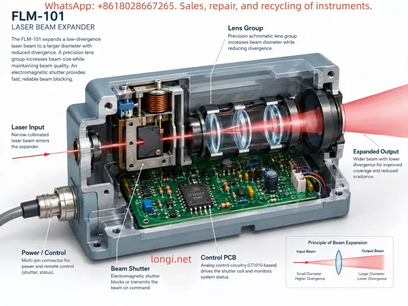
For example, the LaserMike FLM-101-03 contains:
- Analog control circuitry
- LT1010CT power buffer
- Electromagnetic shutter drive system
The electronic circuit controls the opening and closing of the optical shutter.
6. Main Functions of Laser Beam Expanders
6.1 Increasing Laser Beam Diameter
The primary function is expanding the beam diameter.
Applications include:
- Wire diameter measurement
- Cable inspection
- Tube measurement
- Precision dimensional analysis
6.2 Reducing Beam Divergence
A larger beam diameter allows the laser to maintain better collimation.
This is important for:
- Long-distance measurement
- Large inspection areas
- Optical communication
6.3 Improving Measurement Stability
In industrial measurement systems, beam quality directly affects measurement accuracy.
For example, a laser diameter gauge typically works like:
Laser Source

      ↓

Beam Expander

      ↓

Measurement Field

      ↓

Receiver
A stable expanded beam creates a more accurate measurement curtain.
6.4 Increasing Scanning Range
Beam expanders are widely used in:
- Laser scanning systems
- 3D measurement
- Machine vision
- Automated inspection
7. Applications of Laser Beam Expanders
7.1 Laser Diameter Measurement Systems
This is one of the most common industrial applications.
Examples:
- LaserMike optical micrometers
- Laser diameter gauges
- Wire and cable inspection systems
Applications:
- Electrical wire
- Optical fiber
- Plastic tubing
- Metal wire
Measurement principle:
The laser creates a measurement field. When an object blocks part of the beam, the receiver calculates the object size.
7.2 Laser Processing Equipment
Applications include:
- Laser cutting
- Laser welding
- Laser marking
Beam expansion improves:
- Beam quality
- Processing stability
- Energy distribution
7.3 Scientific Optical Systems
Used in:
- Laser interferometers
- Spectroscopy
- Optical experiments
- Research laboratories
7.4 Free-Space Laser Communication
Long-distance laser communication requires:
- Low divergence
- High beam stability
Beam expanders improve transmission performance by reducing beam spreading.
8. Correct Usage of Laser Beam Expanders
8.1 Laser Safety
Many beam expanders are used with:
- Class 3B lasers
- Class 4 lasers
Safety rules:
Do not:
- Look directly into the output aperture
- Observe laser emission with eyes
- Use reflective objects for testing
8.2 Optical Lens Cleaning
Contaminated lenses may cause:
- Reduced optical power
- Beam distortion
- Measurement errors
Recommended cleaning tools:
- Optical cleaning tissue
- Lens cleaning solution
- Dust-free swabs
Avoid:
- Ordinary paper
- Rough cloth
8.3 Avoid Mechanical Shock
The internal optical alignment may require micron-level precision.
Strong impact can cause:
- Lens displacement
- Optical axis deviation
- Measurement errors
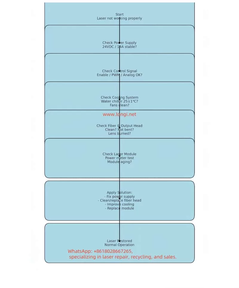
9. Common Failure Analysis
Failure 1: No Laser Output
Possible causes:
Beam shutter closed
Check:
- Mechanical shutter position
- Control signal
Control circuit failure
Possible problems:
- Damaged driver transistor
- Failed power buffer
- Broken electromagnetic coil
Missing external control signal
Failure 2: Abnormal Laser Spot
Possible causes:
- Dirty lens
- Damaged optical coating
- Optical misalignment
Failure 3: Incorrect Expansion Ratio
Possible causes:
- Mechanical adjustment failure
- Lens position change
- Internal mechanism blockage
Failure 4: Electronic Control Failure
Check:
- Power supply
- Driver circuit
- Output stage
For example:
A damaged LT1010CT power buffer may cause:
- Shutter failure
- Insufficient actuator current
- Abnormal optical control
10. Testing Methods for Laser Beam Expanders
10.1 Visual Inspection
Check:
- Housing condition
- Optical window
- Connectors
- Labels
Look for:
- Mechanical damage
- Corrosion
- Moisture contamination
10.2 Optical Inspection
Use:
- Low-power visible light source
Check:
- Optical path condition
- Lens contamination
- Abnormal scattering
Never directly observe a high-power laser output.
10.3 Electrical Testing
For beam expanders with electronic control:
Do not apply power immediately.
Recommended procedure:
Step 1: Measure connector resistance
Check:
- Short circuits
- Open circuits
- Coil resistance
Step 2: Identify power supply pins
Use:
- PCB tracing
- Component identification
- Circuit analysis
Confirm:
- Voltage level
- Ground reference
10.4 Beam Shutter Test
Check:
OPEN/CLOSE operation.
Observe:
- Mechanical movement
- Abnormal noise
- Sticking
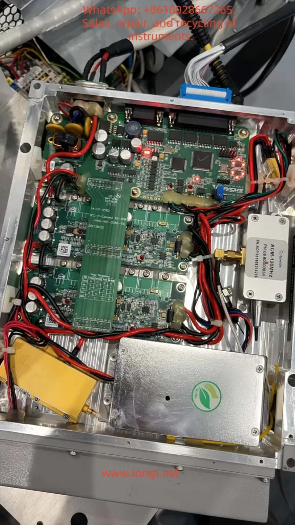
10.5 PCB Testing
Important areas:
Power Section
Check:
- Input protection
- Filtering capacitors
- Voltage regulation
Driver Section
Check:
- LT1010 power buffer
- Transistors
- Electromagnetic coil
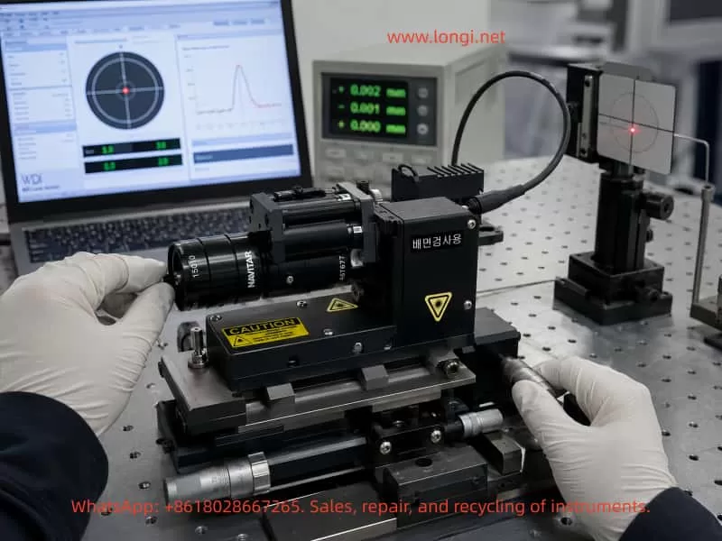
11. Case Study: LaserMike FLM-101-03 Beam Expander
The LaserMike FLM-101-03 is a typical industrial beam expansion module.
Its internal structure includes:
- Optical expansion system
- Beam shutter mechanism
- Analog control PCB
The operating process is:
External Laser Controller

          ↓

7-pin Interface

          ↓

Analog Control Circuit

          ↓

LT1010CT Power Driver

          ↓

Electromagnetic Shutter

          ↓

Laser Beam Control
When testing this type of equipment, engineers should not simply connect a power supply and observe whether it moves.
Correct testing requires:
- Identifying power input pins
- Confirming operating voltage
- Checking actuator resistance
- Testing control electronics
- Verifying optical movement
Old industrial optical devices often use analog circuits rather than modern digital controllers, so careful reverse engineering and measurement are important.
12. Future Development Trends
With the development of:
- Smart manufacturing
- Automated inspection
- Artificial intelligence vision systems
laser beam expanders will continue to play an important role.
Future trends include:
12.1 Higher Precision
Optical manufacturing accuracy will continue moving toward nanometer-level performance.
12.2 Intelligent Control
Future systems may include:
- Automatic calibration
- Beam monitoring
- Digital communication interfaces
12.3 Integrated Optical Modules
Future laser measurement heads may integrate:
- Laser source
- Beam expander
- Receiver
- Controller
Creating complete intelligent measurement systems.
Conclusion
Although a laser beam expander is only one component in a laser system, it plays a critical role in improving beam quality, extending measurement range, reducing divergence, and increasing system stability.
Modern industrial beam expanders are not always simple optical devices. Many models integrate:
- Precision optical lenses
- Beam shutters
- Electromagnetic actuators
- Analog control circuits
- Power driver electronics
Therefore, maintenance and troubleshooting require a comprehensive understanding of:
- Optical principles
- Mechanical structures
- Electronic circuits
- Control methods
By understanding the working principles, internal structure, applications, and testing procedures of laser beam expanders, engineers can improve equipment installation, maintenance efficiency, and fault diagnosis capability in industrial laser measurement systems.