
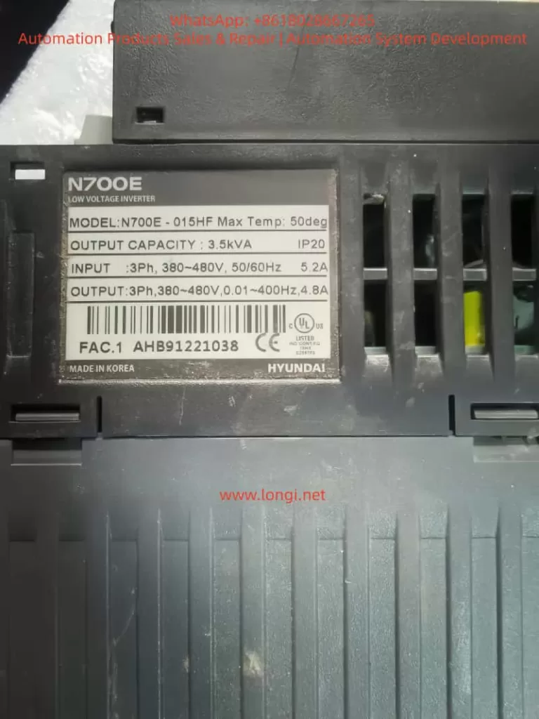
In industrial automation systems, inverters are the core devices for driving motors. The N700E series inverters launched by Hyundai are widely used in textile machinery, conveying systems, fans, pumps, and automation equipment. However, during actual operation, after running for a period of time, the E11 fault code occasionally appears.
Many maintenance technicians are often unfamiliar with the meaning of this fault when they first encounter it, even mistakenly judging it as a power module failure. In fact, the E11 fault belongs to a control system level alarm, usually related to the CPU or control board operation abnormality.
This article provides a systematic analysis of the N700E E11 fault from the following aspects:
- Meaning of the E11 Fault Code
- Principles of the E11 Fault Occurrence
- Analysis of Common Fault Causes
- Detailed Maintenance and Troubleshooting Steps
- Maintenance Case Studies
- Preventive Measures and Maintenance Suggestions
We hope this guide helps engineers quickly locate and resolve the issue.
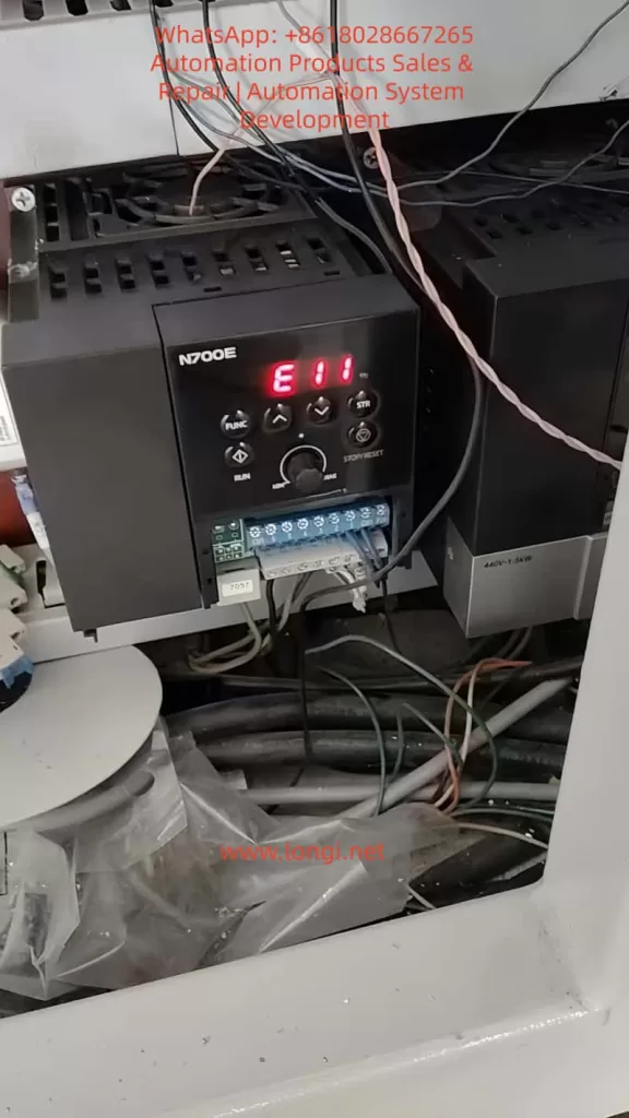
1. Meaning of the N700E Inverter E11 Fault
According to the protection function description in the official N700E manual, the meaning of E11 is:
CPU Error (Main CPU Fault)
The manual explains:
“Inverter main CPU error. When this trip occurs, the inverter power must be turned off and after discharging completely, it can be turned on.”
Key Takeaway:
E11 is not a traditional electrical fault such as:
- Overcurrent
- Overvoltage
- Overload
Instead, it is a Control System Internal Error.
2. N700E Inverter CPU Control System Structure
To understand the E11 fault, we first need to understand the internal control structure of the N700E inverter.
The basic control structure of the N700E mainly includes:
1. Control Board CPU
Main Functions:
- Execute control programs
- Calculate vector control algorithms
- Monitor protection functions
- Communicate with the operation panel
- Manage IO ports
- The CPU is the “brain” of the entire inverter.
2. EEPROM / Flash Memory
Stores:
- Parameter data
- Operation records
- Control programs
- If memory data is abnormal, it will also cause CPU operation errors.
3. Power Management Module
The control board requires multiple voltage levels:
- +5V
- +15V
- +3.3V
- -5V
- If any voltage is abnormal, the CPU will crash.
4. Communication Interfaces
Includes:
- RS485
- Operation panel
- IO ports
- Communication abnormalities may also trigger CPU protection.
3. Principles of E11 Fault Generation
E11 is essentially triggered by the CPU operation abnormality detection mechanism.
The internal program of the inverter continuously detects:
- CPU running status
- Program counter
- Watchdog Timer
- Memory checksum (RAM/Flash)
When an abnormality is detected, the system immediately shuts down and displays E11.
Typical Trigger Conditions:
- Program running deadlock
- RAM verification error
- Flash program error
- CPU Watchdog reset
4. Common Causes of N700E E11 Fault
In actual maintenance, E11 faults are usually caused by the following reasons:
1. Control Board Power Supply Abnormality (Most Common)
Unstable control board power causes CPU operation errors.
- Common Issues: Aging power modules, decreased capacitor capacity, 5V voltage fluctuation, damaged switching power supply IC.
- Symptoms: E11 appears immediately on startup or after running for a while.
- Detection: Measure if 5V, 3.3V, and 15V on the control board are stable.
2. Control Board Capacitor Aging
Many N700E units have been in use for over ten years. Capacitor aging is a very common problem.
- Key Locations: 470uF, 100uF, 47uF electrolytic capacitors on the control board.
- Mechanism: As ESR (Equivalent Series Resistance) increases, power supply ripple increases, leading to program errors.
3. CPU Crystal Oscillator Failure
CPU operation relies on the crystal oscillator (usually 8MHz, 16MHz, or 20MHz).
- Symptoms: Random E11 errors or failure to start.
4. Memory Data Corruption
EEPROM or Flash data corruption caused by:
- Strong electrical interference
- Abnormal parameter writing
- Sudden power loss
- Result: CPU fails the checksum during startup.
5. Control Board Moisture or Contamination
In environments like textile mills, chemical plants, or metallurgical plants:
- Dust, oil mist, and water vapor cause PCB leakage and IO port interference, triggering CPU errors.
6. External Strong Interference
Interference from contactors, welders, or lightning strikes entering through control lines can cause CPU reset.
7. Control Board Hardware Damage
Rarely, the CPU itself is damaged due to lightning, static electricity, or power surges. This usually requires replacing the control board.
5. Detailed E11 Fault Troubleshooting Flow
Maintenance personnel can follow these steps:
Step 1: Power Cycle Reset
Follow the manual: Turn off power and wait 10 minutes for internal capacitors to discharge completely. Then power on again.
- If the fault disappears: It was a temporary CPU glitch.
Step 2: Measure Control Power Supply
Focus on detecting control board voltages:
| Voltage | Normal Range |
|---|---|
| 5V | 4.9 – 5.1V |
| 3.3V | 3.2 – 3.4V |
| 15V | 14 – 16V |
- If fluctuating: Check the power module.
Step 3: Inspect Control Board Capacitors
Check electrolytic capacitors for bulging, leaking, or high ESR.
- Recommendation: Replace all aging capacitors preventatively.
Step 4: Check Crystal Oscillator
Use an oscilloscope to detect the crystal waveform.
- Normal: Stable sine wave.
- Abnormal: Frequency drift or no signal.
Step 5: Clean the Control Board
Use alcohol or electronic cleaner to remove oil, dust, and moisture from the PCB surface.
Step 6: Re-flash Program
If EEPROM is confirmed damaged, the program/parameters need to be re-written/re-burned.
Step 7: Replace Control Board
If the CPU is physically damaged, replace the control board.
6. Field Maintenance Case Study
Case: An N700E-022LF inverter in a textile factory showed E11.
Phenomenon: Alarm appeared immediately upon power-up.
Inspection Process:
- Measure Power: Found 5V voltage was fluctuating between 4.6V and 5.2V.
- Open Machine: Found a 470uF capacitor on the control board was bulging.
- Repair: Replaced the capacitor.
- Result: Fault cleared after power-on; equipment resumed operation.
7. How to Prevent E11 Faults
To reduce such issues, take the following measures:
- Regular Maintenance: Inspect capacitors, fans, and wiring every 3 years.
- Strengthen Grounding: Ensure the inverter is reliably grounded to prevent interference.
- Shield Control Lines: Use shielded cables for control signals and ground the shield layer.
- Install Filters: Install EMI filters on the power supply side.
- Prevent Overheating: Ensure good heat dissipation; keep ambient temperature below 50°C.
8. Summary
The E11 fault in the Modern N700E inverter is a control system level alarm indicating a Main CPU operation abnormality.
Common Causes:
- Control board power issues
- Capacitor aging
- Crystal oscillator anomalies
- Memory data errors
- Environmental interference
- Control board damage
Recommended Repair Order:
- Power cycle reset
- Check control power supply
- Inspect capacitors
- Check crystal oscillator
- Clean control board
- Replace control board (if necessary)
By following this systematic detection process, most E11 faults can be repaired quickly and cost-effectively.