1. Overview of the Fault Symptom
During the maintenance and commissioning of Delta C2000 series inverters, technicians may occasionally encounter a fault message on the keypad display showing “VFDr / Read VFD Info Er”. At first glance, this fault does not resemble common inverter faults such as overcurrent, overvoltage, undervoltage, overload, phase loss, ground fault, or overheating. Instead, it points more toward an internal communication or data-reading problem.
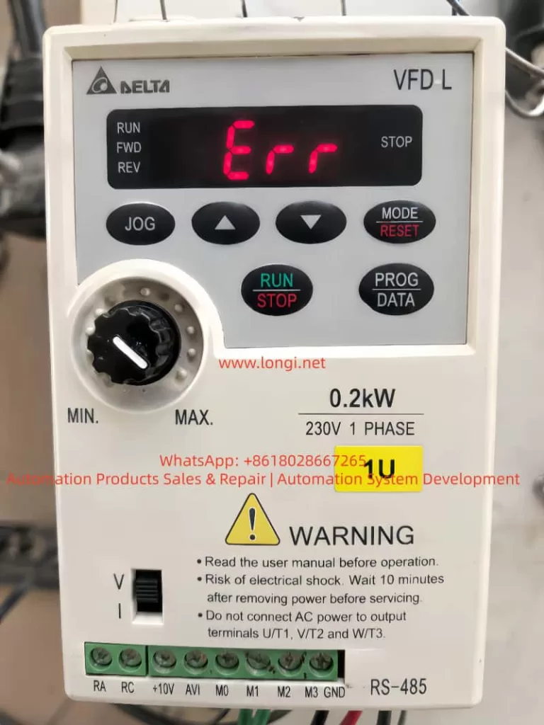
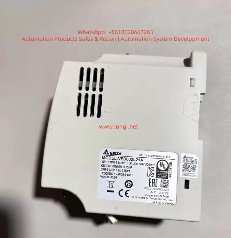
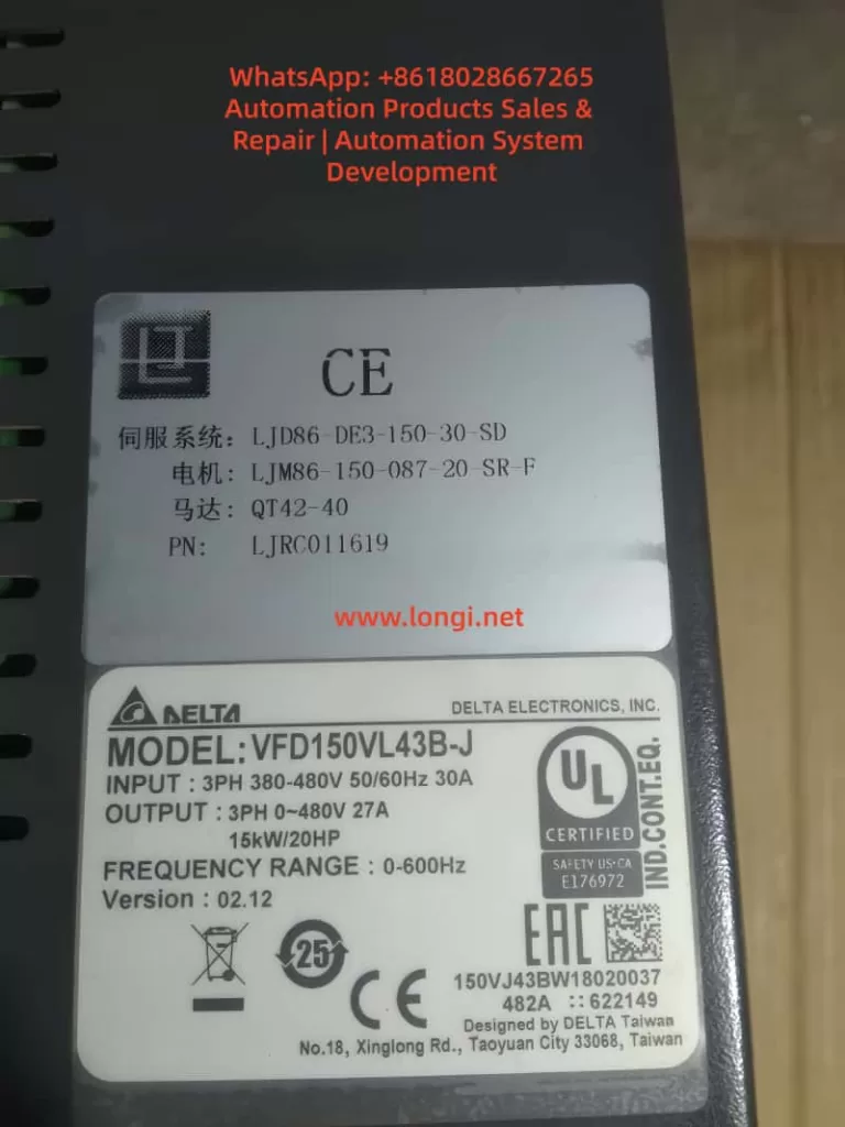
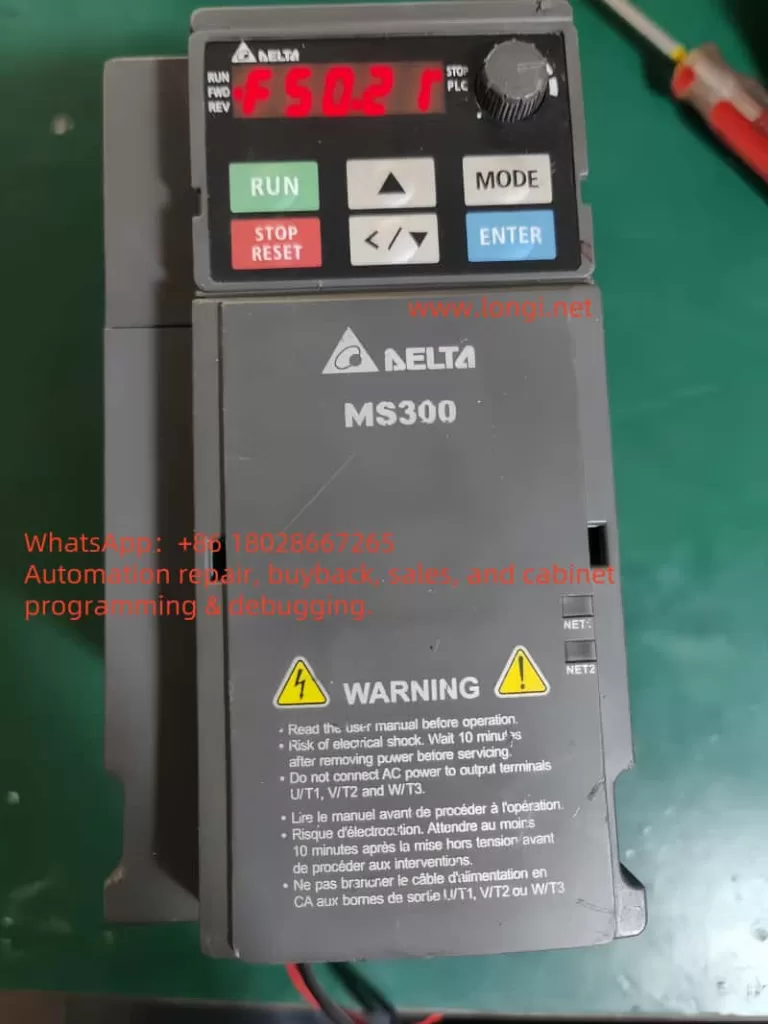
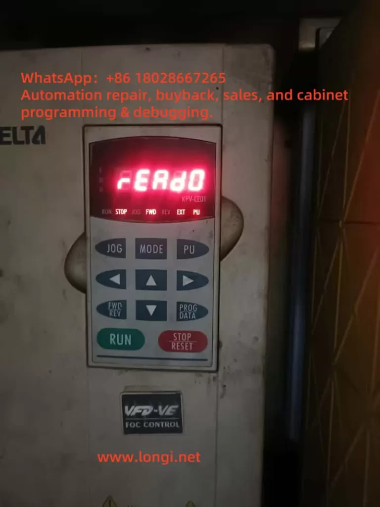
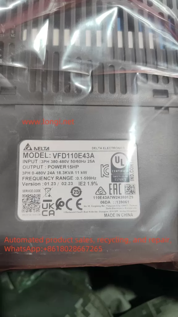
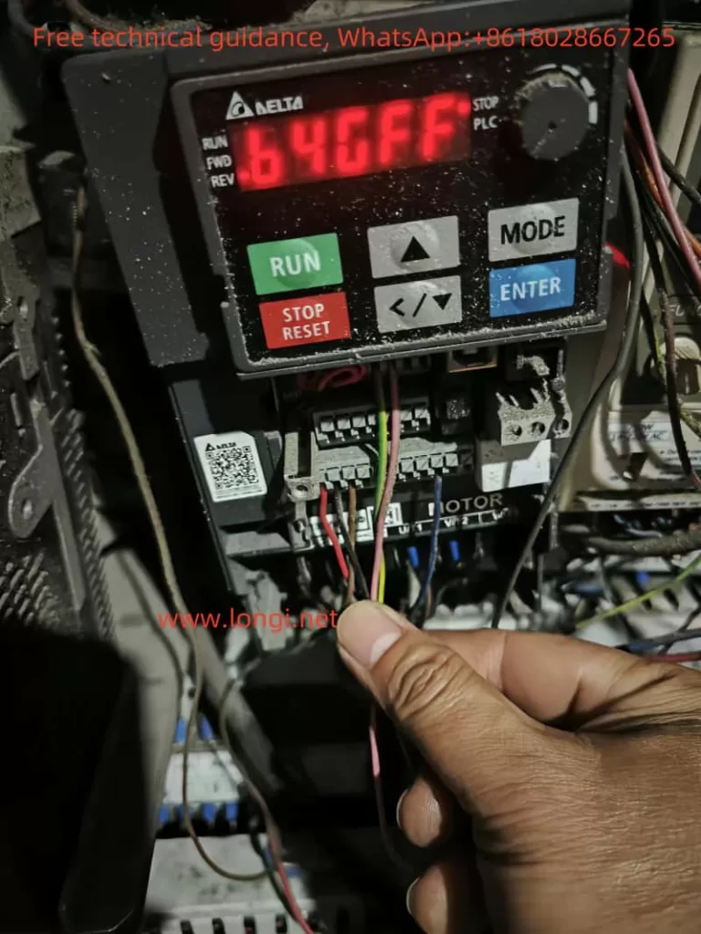
Taking a Delta C2000 inverter model VFD040C43A-21 as an example, this unit belongs to the three-phase 380–480V input class, with an output power of approximately 4kW / 5HP. After power-up, the keypad lights up normally, but the display shows:
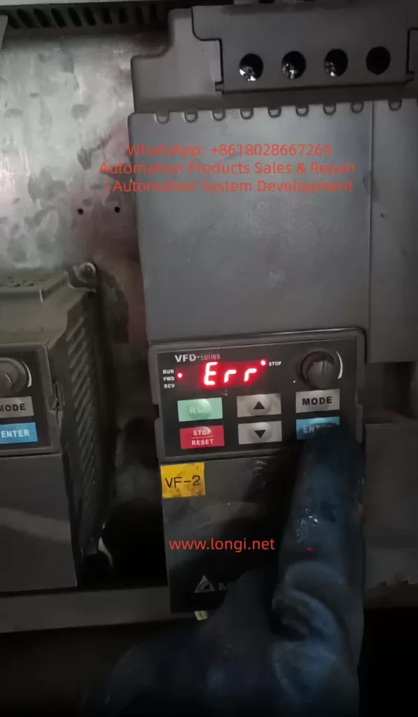
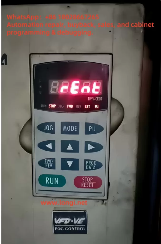
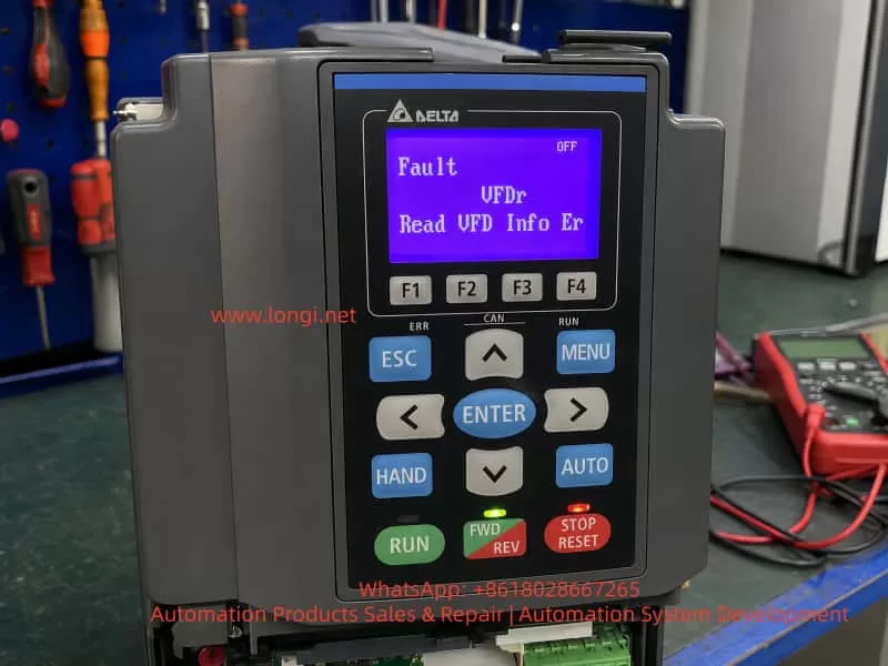
Fault
VFDr
Read VFD Info Er
From the literal meaning, VFDr can be understood as an abnormal condition during the keypad’s reading of VFD information. The English message “Read VFD Info Er” means “Read VFD Info Error”, indicating that the keypad has failed to read the inverter’s internal information correctly.
The key point of this fault is that the keypad, control board, memory, communication interface, or low-voltage control power supply may have a data exchange problem. As a result, the keypad cannot correctly read the inverter model, parameter information, status data, or internal identification information.
Therefore, the VFDr fault should not be simply understood as a damaged power module, nor should it be directly classified as a motor-side fault. It is more accurately described as an information-reading failure between the human-machine interface and the inverter control system. During repair, troubleshooting should focus first on the keypad, keypad connector, control board communication circuit, low-voltage power supply, memory devices, and the general condition of the control board.
2. Essential Meaning of the VFDr Fault
The keypad of an inverter is not merely a simple display screen. It usually performs several functions:
It displays operating frequency, current, voltage, fault codes, and status information. It allows parameter reading and modification. It executes commands such as start, stop, forward/reverse operation, and reset. It exchanges data with the main control board through a communication interface. During power-up, it reads the inverter model, capacity, firmware version, parameter area, status flags, and other internal information.
When the keypad displays “Read VFD Info Er”, it means that the keypad has failed while reading internal information from the inverter. This failure may occur at several levels.
The keypad itself may not be working properly. The connection between the keypad and the inverter control board may be poor. The control board may not be responding correctly to the keypad’s request. The internal memory data on the control board may be abnormal, causing the keypad to read invalid information. The low-voltage control power supply may be unstable, causing the MCU, memory, or communication IC to operate abnormally. The control board may be affected by moisture, oxidation, contamination, cold solder joints, or connector damage, resulting in communication failure.
From a repair perspective, VFDr is a communication and data-reading fault, not a typical power output fault. This distinction is very important. If the fault is incorrectly judged as an IGBT, rectifier bridge, DC bus capacitor, or driver board failure, the repair direction will be wrong and a great deal of time may be wasted.
3. Basic Structure of the Delta C2000 Inverter
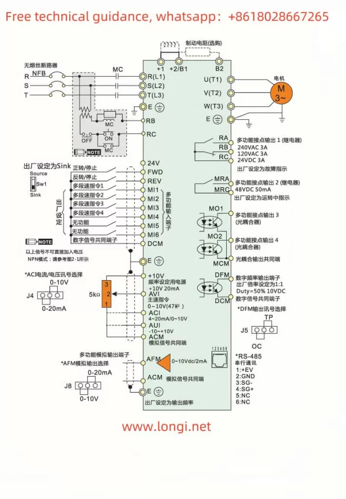
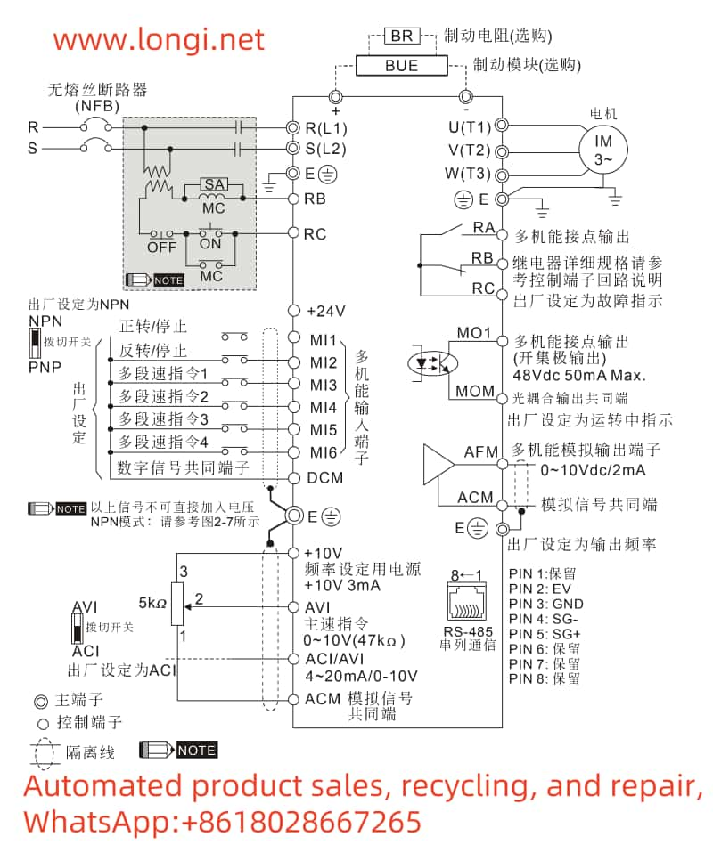
To analyze the VFDr fault accurately, it is necessary to understand the basic electrical structure of the C2000 series inverter. In general, an inverter consists of the following sections.
3.1 Main Power Circuit
The main power circuit includes the input rectifier, DC bus, pre-charge circuit, braking unit, inverter IGBT module, current detection circuit, and output terminals. Its function is to rectify three-phase AC power into DC power, then use the IGBT inverter section to output three-phase AC power with adjustable frequency and voltage.
Common main circuit faults include input phase loss, DC bus overvoltage, DC bus undervoltage, IGBT short circuit, output ground fault, output phase loss, and braking unit faults. These faults usually appear as protection-related codes such as OC, OV, LV, GF, OH, or OL.
VFDr does not usually point first to a main power circuit fault. Even if the power board is damaged, it may not directly cause VFDr. Conversely, even if the power section is normal, the inverter may still display VFDr due to abnormal communication, memory failure, or control board problems.
3.2 Control Power Supply
The control power supply usually generates several low-voltage rails through a switching power supply circuit, such as 24V, 15V, 5V, and 3.3V. The exact voltage configuration may vary by model, but the general functions are as follows.
The 24V supply is often used for relays, external terminals, fan control, or interface circuits. The 15V supply may be used for analog circuits, driver front-end circuits, or operational amplifiers. The 5V supply is commonly used for communication ICs, digital logic, and some interface circuits. The 3.3V supply is often used for the main MCU, DSP, Flash, EEPROM, or logic chips.
If the 5V or 3.3V supply is unstable, communication between the keypad and the control board may fail. Slight ripple, a low voltage level, or abnormal power-on reset timing may all cause data-reading errors. During repair, it is not enough to check only whether voltage is present. The technician should also confirm whether the voltage is stable, whether ripple is excessive, and whether the power-up sequence is normal.
3.3 Main Control Board
The main control board is the brain of the inverter. It handles parameter processing, operation logic, fault protection, PWM output, communication management, and keypad interaction. It usually contains an MCU or DSP, memory devices, communication ICs, crystal oscillator, reset circuit, analog sampling circuits, and digital input/output circuits.
The VFDr fault is closely related to the control board. If the control board cannot return correct device information to the keypad, the keypad will report a reading error. Control board abnormalities may be caused by several factors:
The MCU fails to start correctly. The crystal oscillator does not oscillate or has an abnormal frequency. The reset circuit is abnormal. Flash or EEPROM data is damaged. The communication IC is faulty. Interface protection components are shorted. The low-voltage power supply is abnormal. The board is affected by moisture or corrosion. The program area or parameter area is corrupted.
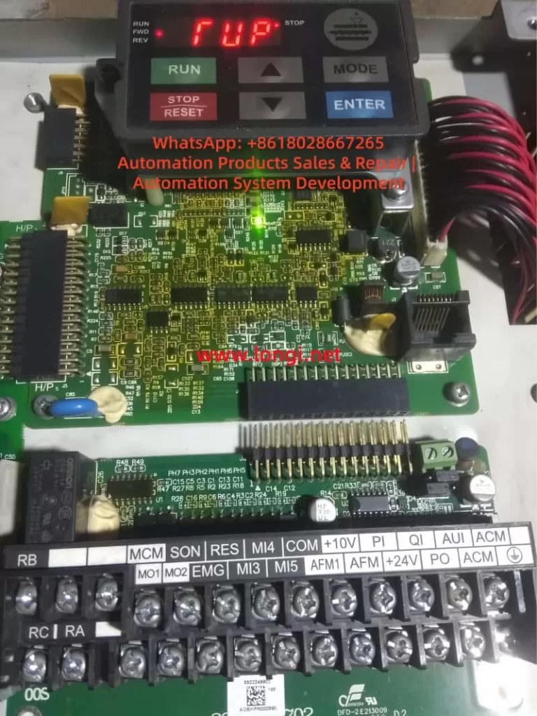
3.4 Keypad and Interface Section
The keypad is connected to the inverter body through pins, a ribbon cable, an RJ45 connector, or a similar interface. The keypad usually contains its own MCU, key scanning circuit, display driver, communication interface, and sometimes memory-related devices. It is not a passive display; it is a small communication terminal.
If the keypad connector is oxidized, has poor contact, bent pins, a broken ribbon cable, or a loose socket, VFDr may occur. The same fault may also occur if the keypad’s internal communication IC is damaged. This is especially common in second-hand units, equipment stored for a long time, devices exposed to moisture, or machines used in dusty industrial environments.
4. Difference Between VFDr and Common Operating Faults
When technicians see an inverter fault, they may immediately think of the motor, load, IGBT, or power module. However, the logic for diagnosing VFDr is different.
4.1 Common Operating Faults Are Usually Related to Load or Power Circuit Conditions
For example, an overcurrent fault normally requires checking motor insulation, output short circuit, acceleration time, mechanical load jam, IGBT condition, and current detection circuits. An overvoltage fault requires checking input voltage, deceleration time, braking resistor, and braking unit. An overheating fault requires checking the fan, heat sink, temperature sensor, and ambient temperature.
These faults usually occur during start-up, acceleration, operation, deceleration, or load changes.
4.2 VFDr Usually Occurs During Power-Up or Information Reading
VFDr often appears immediately after the inverter is powered on, or when the keypad attempts to enter a menu or read internal information. It is not directly related to whether the motor is connected or whether the load is running. Even if no motor is connected, the inverter may still display VFDr.
This indicates that the fault is closer to the control layer rather than the output power layer.
4.3 VFDr Is Not Simply a Parameter Error
Some technicians may see “Read VFD Info Error” and assume that the parameters are incorrect, then try to restore factory settings. In reality, when the keypad cannot correctly read inverter information, forced initialization may not be effective. The problem may not be parameter setting error; the real issue may be that the keypad cannot establish reliable communication with the control board, or the control board cannot correctly read its own internal information.
If the control board memory is damaged, the communication link is abnormal, or the low-voltage power supply is unstable, restoring parameters will not solve the root cause.
5. Possible Causes of the VFDr Fault
5.1 Poor Keypad Contact
This is one of the most common and easiest causes to eliminate. Industrial environments are complex. After long-term operation, the keypad interface may become oxidized, loose, deformed, or contaminated with dust. After transportation, disassembly, or maintenance, the keypad may also be improperly seated.
The correct method is to power off the inverter, remove the keypad, and inspect the connector and pins for oxidation, blackening, bending, breakage, or looseness. The connector may be cleaned using electronic contact cleaner, then dried thoroughly before reinstallation. If available, a known-good keypad from the same series should be used for cross-testing.
If replacing the keypad clears the fault, the original keypad or its connector is likely defective. If the VFDr fault remains after replacing the keypad, the problem is more likely inside the inverter control board.
5.2 Keypad Failure
The keypad itself contains electronic circuits. After long-term use, it may develop MCU failure, communication IC failure, display driver fault, or Flash data abnormality. If the keypad has been affected by electrostatic discharge, hot plugging, external communication interference, or moisture, internal damage may occur.
A faulty keypad may show garbled characters, no key response, failure to enter menus, read failure, fixed fault display, or communication interruption. The best diagnostic method is still cross-testing: install the suspected keypad on a known-good inverter, or install a known-good keypad on the faulty inverter. Cross-testing is more direct than only measuring voltage.
5.3 Abnormal Keypad Communication Line
The keypad usually exchanges data with the control board through serial communication. The communication path may contain transceiver ICs, protection diodes, TVS diodes, resistors, capacitors, isolation devices, and other components. If any of these components becomes shorted, open, or degraded, communication may fail.
Common problems include damaged communication ICs, shorted TVS diodes, open or drifted resistors near the interface, cold solder joints, corroded traces, broken ribbon cables, PCB trace damage, and leakage in ESD protection devices.
During repair, a multimeter can be used to check whether the resistance from each connector pin to ground is abnormal. If an oscilloscope is available, the communication line should be checked for data waveforms. Under normal conditions, there should be data exchange between the keypad and the control board after power-up. If the signal remains permanently high, permanently low, or severely distorted, the communication link is abnormal.
5.4 Abnormal Low-Voltage Control Power Supply
In VFDr faults, low-voltage power supply problems are often overlooked. Many technicians focus only on the DC bus voltage and power module, but do not carefully measure the control power supply. In fact, an unstable control power supply can create many symptoms that look like communication faults.
The following points should be checked:
Whether 5V is stable. Whether 3.3V is stable. Whether there is a voltage drop during power-up. Whether ripple is excessive. Whether electrolytic capacitors have aged. Whether the DC-DC converter or linear regulator is overheating. Whether the reset circuit is releasing normally. Whether the low-voltage power rail has a short circuit or leakage load.
If the 5V rail is low, for example around 4.5V, the communication IC may still operate marginally, but the data error rate will increase significantly. If the 3.3V rail has ripple or momentary dropouts, the main MCU may repeatedly reset, causing the keypad to fail when reading inverter information.
5.5 Main MCU or DSP Not Starting Correctly
If the main control chip does not start correctly, the keypad cannot read valid inverter information. Causes may include abnormal crystal oscillator operation, reset circuit failure, power supply fault, program memory corruption, or failure of the chip itself.
The technician can measure whether the crystal oscillator has a proper oscillation signal, whether the reset pin level is normal, and whether the main control supply voltage is correct. If the main control chip has abnormal heating, abnormal supply current, or no response on all communication lines, damage to the MCU or program area should be considered.
This type of fault is more difficult to repair. It normally requires an oscilloscope, logic analyzer, thermal camera, adjustable power supply, and comparison with a known-good board of the same model.
5.6 Flash, EEPROM, or Parameter Memory Abnormality
Another important diagnostic direction for “Read VFD Info Error” is the memory section. The inverter stores model information, capacity information, parameter data, firmware version, calibration data, and other internal information. If the memory chip is damaged, or if internal data is lost, corrupted, or fails checksum verification, the control board may be unable to provide correct VFD information to the keypad.
Common causes of memory faults include long-term storage, power failure during writing, surge or electrostatic damage, chip aging, incorrect maintenance operation, moisture-induced leakage around chip pins, and failed firmware or parameter copying.
If the memory area is abnormal, the inverter may not only display VFDr, but may also show incorrect model identification, incorrect capacity identification, failure to save parameters, failure to restore factory settings, or repeated alarms after power-up.
5.7 Moisture, Contamination, or Corrosion on the Control Board
Industrial inverters are often installed in environments containing dust, oil mist, water vapor, or metal particles. Once the control board is affected by moisture or contamination, slight leakage may occur. Digital communication circuits are sensitive to leakage and impedance changes. Even minor contamination may affect data transmission.
The control board should be checked carefully for green copper corrosion near connectors, blackened chip pins, water stains, oil residue, dust accumulation, oxidized ribbon cable sockets, moldy or cracked solder joints, leaking capacitors, and cracked protective coating.
For slight contamination, the board can be cleaned with anhydrous alcohol or dedicated electronic cleaner and then dried thoroughly. For severe corrosion, trace repair, component replacement, or control board replacement may be required.
5.8 External Communication or Expansion Module Interference
Some Delta C2000 inverters are connected to external communication modules, expansion cards, PLCs, HMIs, or fieldbus systems. If an expansion module is abnormal, it may affect internal communication or power-up identification. Although VFDr is more closely related to keypad information reading, external communication interference should also be ruled out in complex systems.
During troubleshooting, all unnecessary external wiring should be disconnected first, leaving only the required input power and keypad. This puts the inverter into a minimum system condition. If the fault disappears after external communication is disconnected, the communication module, parameter settings, shielding, grounding, termination resistor, or external device status should be checked.
6. Systematic Diagnostic Procedure
The VFDr fault should be diagnosed according to the principle of from outside to inside, from simple to complex, from interface to control board. The following procedure is recommended.
6.1 Confirm the Exact Fault Display
First confirm that the display really shows:
VFDr
Read VFD Info Er
Do not rely only on verbal descriptions. A difference of one letter in a fault code may lead to a completely different repair direction. Take photos of the fault display, nameplate, voltage class, operating environment, and wiring condition.
6.2 Power Off, Discharge, and Power On Again
An inverter contains large DC bus capacitors. Even after power is removed, dangerous voltage may remain inside. Before removing the keypad or inspecting internal circuits, power must be disconnected and the DC bus voltage must fall to a safe level. It is recommended to wait more than 10 minutes and measure the voltage between P and N, or DC+ and DC-, to confirm that the bus is discharged.
After repowering the inverter, observe whether the fault remains. If it disappears intermittently, poor contact, unstable power-up, or moisture may be suspected. If it appears every time, the fault is stable and easier to locate.
6.3 Inspect the Keypad and Connector
Remove the keypad and inspect the interface. Clean the connector and pins, then reinstall the keypad. Confirm that it is fully inserted, locked in place, and not loose.
If a known-good keypad from the same series is available, cross-testing should be performed. The test result is highly valuable:
If a known-good keypad works normally on the faulty inverter, the original keypad is likely defective. If a known-good keypad still shows VFDr on the faulty inverter, the fault is likely inside the inverter control board. If the suspected keypad also shows the same fault on a normal inverter, the keypad itself is very likely defective. If the suspected keypad works normally on another inverter, the control board or interface of the faulty inverter should be checked.
6.4 Test the Inverter in Minimum System Condition
Disconnect the motor cable, external control terminals, communication cables, and expansion cards. Keep only the necessary input power and keypad. This eliminates external wiring, communication interference, and terminal short-circuit factors.
If VFDr remains under minimum system conditions, the fault is basically internal to the inverter. If the inverter returns to normal, reconnect external wiring step by step to identify the circuit that triggers the fault.
6.5 Check the Control Power Supply
After opening the cover, measure the key power supply points on the control board. The focus should be on 5V, 3.3V, 24V, and other low-voltage rails. During measurement, do not only check static voltage. Observe whether there is a voltage drop during power-up or when the fault appears.
If an oscilloscope is available, check the power supply ripple. Excessive ripple on digital power rails may cause communication errors and MCU malfunction. For older units, electrolytic capacitors, regulator ICs, DC-DC modules, and switching power supply feedback circuits should be inspected carefully.
6.6 Check Communication Waveforms
In a well-equipped repair environment, an oscilloscope can be used to observe the keypad communication lines. Under normal conditions, there should be data requests and responses between the keypad and the control board after power-up. If only the keypad sends data and there is no response from the control board, the main controller may not have started or the receiving channel may be abnormal. If the control board responds but the waveform amplitude is abnormal or severely distorted, the communication IC, protection devices, or line impedance may be faulty.
If a TVS diode on the communication line is shorted, the waveform may be pulled low or the resistance may be abnormally small. After removing or replacing the abnormal protection component, communication may recover.
6.7 Check Main Controller Start-Up Conditions
If there is no communication response, further check the start-up conditions of the main control chip, including power supply, reset, crystal oscillator, and program memory. If the main controller does not start, the keypad cannot read any valid information.
This step requires stronger electronic repair skills. If no circuit diagram is available, comparison with a known-good board of the same model is useful for judging voltage, waveform, and resistance differences.
6.8 Check Memory and Parameter Area
If the main controller starts and communication waveforms exist, but the information still cannot be read correctly, memory or parameter area abnormality should be suspected. Check the power supply, chip select, clock, and data line waveforms of EEPROM, Flash, FRAM, or other memory devices. Oxidized pins, cold solder joints, or abnormal chip power supply may also cause read failure.
Memory-related faults should not be handled blindly. Some inverter memory devices contain capacity identification, calibration data, and factory information. Replacing the chip with a blank one may cause the inverter to lose capacity identification or fail to operate. Whenever possible, the original data should be preserved. If necessary, data comparison should be performed using the same model and same capacity inverter.
7. Precautions During Repair
7.1 Do Not Hot-Plug the Keypad
Although some inverter keypads support remote mounting or removal, hot-plugging is not recommended during repair. Hot-plugging may generate surge voltage or electrostatic discharge, damaging the keypad communication IC or the main control interface. The correct procedure is to power off the inverter, wait for discharge, confirm safety, and then remove or install the keypad.
7.2 Do Not Immediately Restore Factory Parameters
VFDr is an information-reading error, not a normal parameter setting error. Before communication is restored, factory initialization often cannot be executed correctly. Even if it can be executed, it may erase original parameters and make later commissioning more difficult. In production-line applications, original parameters may include motor nameplate data, control mode, communication address, analog scaling, and protection logic. Random initialization may create additional problems.
7.3 Do Not Immediately Judge the Power Module as Faulty
VFDr does not directly correspond to power module failure. A damaged power module may coexist with other problems, but when VFDr appears alone, the control communication system should be checked first. Blindly removing and testing IGBTs will not solve the reading error and may increase the risk of secondary damage.
7.4 Pay Attention to High-Voltage Safety
The Delta C2000 is an industrial inverter, and the internal DC bus voltage is very high. In a 380V-class inverter, the rectified DC bus voltage can reach approximately 500–700VDC. Even after power is removed, the bus capacitors may still hold dangerous voltage. Before repair, the bus voltage must be measured and confirmed safe. A dark keypad display does not mean the inverter is safe.
7.5 Observe ESD Protection
The keypad, control board, communication ICs, Flash, and EEPROM are all sensitive electronic components. During repair, electrostatic discharge should be avoided. This is especially important when removing and installing the keypad or control board in a dry environment.
8. Typical Diagnostic Logic
When a Delta C2000 inverter displays VFDr after power-up, the following logic can be used.
If the keypad is completely dark, check the control power supply and keypad power first.
If the keypad lights up but displays VFDr, check keypad communication and control board response first.
If replacing the keypad solves the problem, the original keypad or its interface is faulty.
If replacing the keypad does not solve the problem, focus on the control board.
If cleaning the connector solves the problem, poor contact or contamination leakage is confirmed.
If the low-voltage power supply is low, repair the power supply before judging communication.
If the communication line has abnormal resistance to ground, check TVS devices, communication ICs, and nearby interface components.
If the main controller has no crystal oscillation, no reset release, and no communication waveform, check MCU start-up conditions.
If the main controller communicates but information reading still fails, check the memory and parameter area.
If the equipment has been stored for a long time or exposed to moisture, connector oxidation, board contamination, power supply aging, and memory abnormality should be considered high-probability causes.
This diagnostic order helps avoid blind component replacement and improves repair efficiency.
9. Relationship Between VFDr and Long-Term Storage
Inverters that have been stored for a long time are more likely to show VFDr-type faults. There are several reasons.
First, long-term power-off storage can degrade electrolytic capacitors, causing increased ripple in the control power supply during start-up. Second, humid environments can oxidize connectors and cause leakage on the PCB surface. Third, dust and oil contamination accumulated over time can reduce insulation resistance and affect high-impedance communication circuits. Fourth, memory devices or parameter areas in older equipment may develop data abnormalities. Fifth, transportation may loosen the keypad connector, ribbon cable, or socket.
Therefore, for inverters that have been stored for years, it is recommended to perform visual inspection, insulation checking, low-voltage power supply checking, and connector cleaning before power-up. For larger units, capacitor reforming and main circuit safety tests should also be considered to prevent secondary damage caused by direct power-up.
10. Post-Repair Testing
After the VFDr fault is cleared, the repair should not end simply because the keypad no longer reports an error. A full system test should be performed to confirm that both the control system and the power system are operating normally.
Recommended test items include:
Power on the inverter multiple times and confirm that VFDr does not reappear. Enter the parameter menu and confirm that parameters can be read, modified, and saved. Check whether the inverter model, capacity, voltage class, and version information are displayed correctly. Confirm that all keypad buttons work normally. Check whether external terminal inputs and outputs are normal. Check analog input and output functions. Perform no-load operation and observe whether output frequency and voltage are stable. Run the motor at low frequency and observe whether the output current is balanced. Perform acceleration and deceleration tests and confirm that no abnormal alarms occur. Power off and then power on again to confirm that parameter saving is normal.
If the repair involves the memory, control board, or control power supply, parameter retention and repeated power-cycle stability must be tested carefully. Some memory or power supply problems may not appear immediately and may only be exposed after repeated hot and cold tests.
11. Conclusion
When a Delta C2000 series inverter displays VFDr / Read VFD Info Er, the essential fault is that the keypad has failed to read internal information from the inverter. This is different from common main circuit faults such as overcurrent, overvoltage, overload, or short circuit. The repair focus should be placed on the keypad, keypad connector, control board communication circuit, low-voltage control power supply, MCU start-up conditions, and memory data integrity.
In actual repair work, the recommended troubleshooting method is to proceed from outside to inside: first inspect the keypad and connector, then perform cross-testing, check the control power supply and communication waveform, and finally move deeper into the control board, memory, and program data level. For equipment that has been stored for a long time, exposed to moisture, transported, or purchased second-hand, connector oxidation, control board contamination, power supply aging, and parameter storage abnormality are all high-probability causes.
The key to diagnosing VFDr is not to blindly replace power components, but to understand the nature of the fault as an information-reading error. Once the data link between the keypad and the control system is clearly understood, the fault range can be narrowed efficiently by checking power supply, interface, communication, main controller, and memory in sequence.
For technicians, VFDr is a representative control-layer fault. It shows that modern inverters are not just power converters; they are complex systems integrating power electronics, embedded control, digital communication, parameter storage, and human-machine interaction. To repair such equipment accurately, one must understand not only the main power circuit, but also the control board; not only how to test IGBTs, but also how to analyze communication circuits and low-voltage power supplies. Only with this complete diagnostic approach can the real fault be identified and ineffective repair work avoided.