
Inovance HE200 Series Standard Variable Frequency Cabinet Hardware Guide: Cabinet Structure, Main Circuit Components, Control Wiring and Installation
The Inovance HE200 series standard variable frequency cabinet (变频调速柜) is an integrated power drive solution designed for industrial motor control applications. These cabinets combine power distribution, harmonic filtering, motor control, and protection systems into a single enclosure, providing a turnkey solution for applications ranging from HVAC and water supply systems to heavy industrial automation equipment. This comprehensive hardware guide covers the cabinet structure, main circuit components, control wiring specifications, installation requirements, protection systems, and maintenance procedures to ensure safe and reliable operation.
1. Cabinet Structure and Dimensions
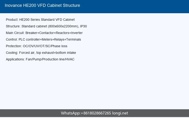
The HE200 series variable frequency cabinet is engineered as a standardized modular enclosure system that houses all necessary electrical components for variable frequency drive (VFD) operation. The cabinet structure follows international standards for industrial electrical equipment enclosures, ensuring compatibility with global installation practices.
1.1 Cabinet Construction
The standard HE200 cabinet is constructed from high-quality cold-rolled steel with a powder-coated finish, providing excellent corrosion resistance and electromagnetic shielding properties. The cabinet frame uses a standardized nine-fold profile design (九折型材), which is the industry standard for industrial control cabinets. This construction method provides exceptional structural rigidity while maintaining a relatively lightweight profile.
The cabinet doors are equipped with seamless gaskets and multi-point locking mechanisms to maintain the specified protection rating. The standard configuration includes a front door with a viewing window for monitoring panel instruments, side panels that are removable for maintenance access, and a cable entry section at the bottom with adjustable cable gland plates.
1.2 Standard Dimensions
The HE200 series cabinets are available in multiple standard sizes to accommodate different power ratings and component configurations. The typical cabinet dimensions follow these ranges:
| Power Range | Height (mm) | Width (mm) | Depth (mm) | Approximate Weight (kg) |
|---|---|---|---|---|
| 7.5-22 kW | 1800-2000 | 600-800 | 400-600 | 80-150 |
| 30-75 kW | 2000-2200 | 800-1000 | 600-800 | 150-300 |
| 90-200 kW | 2200 | 1000-1200 | 800-1000 | 300-500 |
| 220-500 kW | 2200-2400 | 1200-1600 | 1000-1200 | 500-900 |
Custom cabinet dimensions are available upon request for specialized applications or space-constrained installations. All cabinets are designed with a 100mm high base frame (底座) to facilitate cable routing and provide protection against floor-level moisture.
1.3 Internal Layout and Compartments
The HE200 cabinet interior is logically divided into functional compartments to ensure safety, accessibility, and electromagnetic compatibility:
- Power Input Compartment (Top Section): Contains the main circuit breaker, input contactor, AC input reactor, and EMC filter. This compartment is isolated from the control section to minimize electromagnetic interference.
- Inverter Module Compartment (Center Section): Houses the main VFD inverter module, which is the core of the frequency conversion system. This section includes the power terminals and DC bus connections.
- Output Section: Contains the output reactor, output filter, and motor connection terminals. This section may also include the braking unit and braking resistor for applications requiring regenerative braking.
- Control Compartment (Lower or Side Section): Contains the PLC control logic, protection relays, control terminal blocks, and auxiliary power supplies. This compartment is physically separated from power circuits.
- Cooling System: Includes cooling fans, air ducts, and ventilation grills. The cooling system is designed for front-to-back or bottom-to-top airflow patterns depending on the cabinet configuration.
2. Main Circuit Components and Their Functions
The main circuit of the HE200 variable frequency cabinet consists of carefully selected components that work together to provide reliable motor control while protecting both the drive system and the connected motor.
2.1 Main Circuit Breaker (MCCB)
The main circuit breaker serves as the primary disconnecting and protective device for the entire cabinet. It provides short-circuit protection, overload protection, and manual isolation capability. The breaker is typically a molded case circuit breaker (MCCB) with adjustable thermal and magnetic trip settings selected according to the cabinet’s rated current.
The breaker rating is determined by the total input current of the inverter module plus any auxiliary loads. For standard HE200 cabinets, the breaker is sized at approximately 1.25 to 1.5 times the inverter’s rated input current to provide adequate protection margin while avoiding nuisance tripping during normal startup conditions.
2.2 Main Contactor
The main contactor provides automatic control of power supply to the inverter module. It is controlled by the cabinet’s control logic and can be programmed for automatic switching sequences. The contactor coil is typically powered by the control circuit at 220V AC or 24V DC depending on the cabinet configuration.
Important operational note: The contactor should not be used for frequent on-off cycling of the motor, as this can cause excessive charging current stress on the inverter’s DC bus capacitors. Motor start-stop operations should always be performed through the inverter’s control commands rather than by switching the main contactor.
2.3 AC Input Reactor
The AC input reactor is an essential component for improving power quality and protecting the inverter. Its primary functions include:
- Reducing input current harmonics caused by the inverter’s rectifier circuit
- Improving the overall power factor at the input side
- Limiting inrush current during power-on
- Protecting the rectifier diodes from voltage spikes and transients
- Reducing conducted electromagnetic interference back to the power grid
The reactor is typically specified with an inductance value of 2-4% voltage drop at rated current. For HE200 cabinets, the reactor is selected based on the inverter power rating and is mounted in the input compartment with adequate ventilation clearance.
2.4 DC Reactor (Optional)
For higher power ratings or applications requiring enhanced harmonic compliance, a DC reactor can be installed on the DC bus between the rectifier and inverter sections. The DC reactor provides additional harmonic filtering and helps stabilize the DC bus voltage under varying load conditions. When both AC and DC reactors are installed, they work synergistically to achieve higher power factor and lower total harmonic distortion (THD).
2.5 Input Filter (EMC Filter)
The input EMC filter is designed to suppress radio frequency interference (RFI) conducted from the inverter back into the power supply network. This is essential for meeting electromagnetic compatibility standards such as EN 61800-3. The filter contains carefully selected capacitors and inductors arranged in a multi-stage configuration to attenuate both common-mode and differential-mode noise.
The filter must be properly grounded to the cabinet’s PE bus using short, low-impedance connections. The grounding conductor should not exceed 30cm in length for optimal high-frequency performance.
2.6 Inverter Module
The inverter module is the core component of the HE200 cabinet. It converts the fixed-frequency AC input power into variable-voltage, variable-frequency output power for precise motor speed control. Modern HE200 cabinets utilize IGBT-based inverter modules with PWM (Pulse Width Modulation) control technology.
The inverter module typically includes:
- Three-phase bridge rectifier with soft-charge circuit
- DC bus capacitors with pre-charge resistors and contactor
- IGBT inverter bridge with gate drivers
- Current sensors (Hall effect) for each output phase
- DC bus voltage monitoring circuit
- Temperature sensors for heatsink and module monitoring
- Built-in braking chopper (for models with “B” suffix)
2.7 Output Reactor and Filter
The output reactor protects the motor by limiting the rate of voltage rise (dv/dt) at the motor terminals, which is particularly important for long cable runs. High dv/dt can cause motor insulation stress and bearing currents. The output reactor also helps filter high-frequency components from the PWM waveform, resulting in smoother current to the motor.
For applications with very long motor cables (typically over 50 meters) or when operating multiple motors in parallel, an output sine wave filter may be installed instead of or in addition to the output reactor. The sine wave filter converts the PWM waveform into a near-sinusoidal output, virtually eliminating motor insulation and bearing problems.
2.8 Braking Unit and Braking Resistor
When the motor operates in regenerative mode (decelerating or lowering a load), energy flows back from the motor to the inverter’s DC bus, causing the DC voltage to rise. The braking unit monitors the DC bus voltage and, when it exceeds the threshold (typically 760V for 380-480V systems), switches the braking resistor into the circuit to dissipate the excess energy as heat.
The braking resistor is sized based on the regenerative power requirements of the application. For standard duty, the resistor is typically rated for 10% duty cycle (ED). Heavy regenerative applications such as cranes, centrifuges, and elevators require larger resistors with higher duty ratings.
3. Control Circuit Wiring
The control circuit of the HE200 cabinet provides the interface between the user’s automation system and the inverter module. It handles command signals, status feedback, analog references, and communication protocols.
3.1 Control Panel with Meters
The cabinet door is equipped with a control panel that provides local operation and monitoring capabilities. Standard instruments include:
- Voltmeter: Displays input line voltage or output voltage (selectable)
- Ammeter: Displays output current to the motor
- Frequency Meter: Displays output frequency
- Status Indicators: LED indicators for Run, Fault, Power On, and Remote/Local mode
- Emergency Stop Button: Red mushroom-head button for immediate shutdown
- Local Control Buttons: Start, Stop, Reset, and Speed adjustment potentiometers (when in local mode)
3.2 PLC Control Logic
The HE200 cabinet incorporates a programmable logic controller (PLC) that manages the operational sequence of the cabinet components. The PLC program typically handles:
- Startup sequence: Pre-charge control, contactor closure timing, inverter enable
- Shutdown sequence: Inverter disable, contactor opening, discharge verification
- Interlocking: Ensuring proper operation sequence and preventing unsafe conditions
- Signal conditioning: Converting user signals to inverter-compatible formats
- Fault handling: Detecting and responding to abnormal conditions
- Communication: Acting as a gateway between fieldbus networks and the inverter
The PLC is programmed with safety interlocks that prevent the main contactor from closing unless all pre-conditions are satisfied, including proper input voltage, no fault conditions, and proper temperature levels.
3.3 Control Terminal Blocks
The control wiring interface is organized through labeled terminal blocks located in the control compartment. Standard terminals include:
| Terminal Group | Function | Typical Signals |
|---|---|---|
| Digital Inputs (DI) | 24V DC control signals | Start, Stop, Reset, Multi-speed selection, Jog |
| Digital Outputs (DO) | Status indication signals | Running, Fault, Ready, At Speed |
| Analog Inputs (AI) | Speed reference signals | 0-10V or 4-20mA speed command |
| Analog Outputs (AO) | Process monitoring | Output current, output frequency, motor torque |
| Relay Outputs | Alarm and status contacts | Fault relay, Running relay |
| Communication | RS485/Modbus RTU | A, B, GND terminals |
| Auxiliary Power | External power supply | 24V DC, 220V AC, PE |
All control terminals use spring-clamp or screw-type connections suitable for wire sizes from 0.5mm² to 2.5mm². Shielded cables must be used for analog signals and communication lines, with the shield connected to ground at one end only (typically the cabinet side).
3.4 Protection Relays
The protection relay system provides additional safety and equipment protection beyond the inverter’s internal protection functions. Standard protection relays include:
- Thermal Overload Relay: Protects the braking resistor and other auxiliary components from overheating
- Phase Sequence Relay: Detects incorrect phase rotation or phase loss at the input
- Earth Fault Relay: Provides sensitive ground fault detection for the motor circuit
- Temperature Relay: Monitors cabinet internal temperature and can trigger alarms or shutdowns
- Door Interlock Relay: Ensures the cabinet cannot be energized when access doors are open
4. Installation Requirements
Proper installation is critical for the safe and reliable operation of the HE200 variable frequency cabinet. The following requirements must be observed during installation.
4.1 Environmental Requirements
- Location: Indoor installation only, protected from direct sunlight, rain, and corrosive atmospheres
- Temperature: Operating range -10°C to +40°C (up to +50°C with derating). Storage range -20°C to +60°C
- Humidity: Maximum 95% RH, non-condensing
- Altitude: Up to 1000m without derating; above 1000m, derate by 1% per 100m (maximum 3000m)
- Vibration: Less than 5.9 m/s² (0.6g)
- Pollution Degree: Degree 2 (IEC 60664-1)
4.2 Mounting and Clearance
The cabinet must be installed on a flat, level surface capable of supporting its weight. For floor-standing cabinets, anchoring bolts (typically M12 or M16) must be used to secure the cabinet base to the floor. Wall-mounted configurations require a structural wall capable of supporting at least 3 times the cabinet weight.
Minimum clearance requirements around the cabinet:
| Direction | Minimum Clearance | Purpose |
|---|---|---|
| Front (door side) | 1000mm | Maintenance access and air intake |
| Rear | 600mm | Cable access and rear panel removal |
| Left/Right sides | 200mm | Side panel removal and heat dissipation |
| Top | 300mm | Hot air exhaust and top cable entry |
4.3 Power Cable Requirements
Power cables must be sized according to the inverter’s rated current, local electrical codes, and voltage drop considerations. As a general guideline:
- Input power cables: Sized at 1.0 to 1.25 times the inverter rated input current
- Output motor cables: Sized at 1.0 times the motor rated current, with consideration for harmonic heating
- Ground conductors: Minimum 50% of phase conductor size, or per local code requirements
Shielded cables are recommended for motor connections to reduce electromagnetic emissions. When shielded cables are used, the shield must be grounded at both ends using 360-degree circumferential bonding clamps for optimal high-frequency performance.
4.4 Grounding Requirements
Proper grounding is essential for safety and electromagnetic compatibility. The HE200 cabinet includes a comprehensive grounding system:
- A main PE (Protective Earth) busbar running the full height of the cabinet
- All metal enclosure parts, doors, and internal partitions bonded to the PE bus
- Component chassis grounds connected to the PE bus with dedicated conductors
- External PE connection point at the cabinet base with minimum 16mm² copper conductor
The grounding system must be connected to the facility’s main grounding electrode with a resistance not exceeding local code requirements (typically 4 ohms or less). The PE conductor must not carry any operational current under normal conditions.
5. Protection Systems
The HE200 cabinet incorporates multiple layers of protection to safeguard personnel, equipment, and the power distribution system.
5.1 Personnel Safety Protections
- Door Interlocks: The main circuit breaker and control power cannot be energized when access doors are open
- Emergency Stop: The red E-stop button immediately opens the main contactor and disables the inverter
- IP Protection Rating: Standard cabinets provide IP30 or IP41 protection against accidental contact with live parts
- Insulation Barriers: All live parts above 50V are protected against accidental contact
- Warning Labels: Safety labels in multiple languages warn of electrical hazards and high temperatures
5.2 Equipment Protection Functions
The inverter module provides comprehensive internal protection including:
- Overcurrent Protection: Instantaneous trip at approximately 200% of rated current
- Overload Protection: Inverse-time overload curve based on motor thermal model (110% for 60 seconds typical)
- Overvoltage Protection: DC bus overvoltage trip at approximately 820V (for 380-480V systems)
- Undervoltage Protection: DC bus undervoltage trip at approximately 350V
- Overtemperature Protection: Heatsink temperature monitoring with programmable trip point
- Phase Loss Protection: Detection of input and output phase loss
- Ground Fault Protection: Detection of output ground faults
- Stall Prevention: Automatic current limiting during acceleration, deceleration, and steady-state operation
5.3 External Protection Coordination
The cabinet’s external protection devices coordinate with the inverter’s internal protections to provide complete system protection:
- The main circuit breaker provides short-circuit protection for the entire cabinet
- The thermal overload relay protects components not covered by the inverter’s electronic protection
- The phase sequence relay prevents operation with incorrect phase rotation
- The temperature relay monitors cabinet ambient temperature and can initiate cooling fan operation or alarm signals
6. Maintenance Procedures
Regular maintenance ensures long-term reliability and prevents unexpected downtime. The following maintenance schedule is recommended.
6.1 Daily Inspections
- Verify that the cabinet cooling fans are operating and airflow is unobstructed
- Check indicator lights on the control panel for normal status
- Monitor operating parameters (current, voltage, temperature) for abnormal readings
- Listen for unusual noises from the cabinet or connected motor
- Verify that the environment temperature is within specified limits
6.2 Monthly Maintenance
- Inspect and tighten all power terminal connections (check for discoloration or heating signs)
- Inspect control terminal connections for looseness
- Clean or replace cabinet air intake filters
- Check operation of door interlocks and emergency stop button
- Verify proper function of all indicator lights and meters
6.3 Annual Maintenance
- Perform thorough cleaning of all cabinet interior surfaces using dry compressed air or vacuum
- Inspect and clean inverter module heatsinks; ensure cooling fins are free of dust buildup
- Check and record DC bus capacitor condition (ESR measurement if available)
- Test all protection relays for proper operation
- Verify torque on all electrical connections according to manufacturer’s specification
- Inspect cable insulation for signs of aging or damage
- Measure and record insulation resistance of motor cables and motor windings
- Test emergency stop function and door interlock circuits
- Calibrate panel meters if drift is suspected
6.4 Component Replacement
Key components have typical service lives that should be monitored:
| Component | Typical Lifespan | Replacement Indicators |
|---|---|---|
| Cooling Fans | 5-7 years | Noise increase, reduced airflow, bearing wear |
| DC Bus Capacitors | 7-10 years | Capacitance reduction >20%, ESR increase |
| Braking Resistor | 5-10 years | Open circuit, resistance change >10% |
| Contactors | 10+ years | Welded contacts, excessive contact wear, coil failure |
| Filters (EMC) | 10+ years | Capacitor leakage, inductor overheating |
6.5 Troubleshooting Common Issues
| Symptom | Possible Cause | Remedy |
|---|---|---|
| Cabinet overheating | Blocked air filters, failed cooling fans, high ambient temperature | Clean filters, replace fans, improve ventilation |
| Unexpected tripping | Overload, short circuit, ground fault, protection relay settings | Check load conditions, inspect cables, verify settings |
| Excessive noise or vibration | Loose components, fan imbalance, resonant mounting | Tighten fasteners, replace fan, check mounting |
| Control malfunction | Loose control wiring, EMI interference, failed PLC I/O | Check connections, verify shielding, test I/O |
| Inverter fault codes | See inverter manual for specific fault diagnosis | Follow inverter troubleshooting guide |
7. Commissioning Procedure
After installation and before full operation, the HE200 cabinet must be properly commissioned:
- Visual Inspection: Verify all components are properly installed, connections are tight, and no shipping damage is present
- Insulation Test: Perform 500V DC megger test on all power circuits (minimum 5 MΩ)
- Control Verification: Apply control power only and verify all control circuits, indicators, and interlocks function correctly
- Pre-charge Test: Close the main breaker and verify the DC bus charges smoothly without abnormal sounds or smells
- No-Load Test: Run the inverter at low frequency without motor load to verify basic operation
- Motor Parameter Setup: Enter motor nameplate data into the inverter and perform auto-tuning if required
- Loaded Test: Run the motor through its operating speed range under controlled load conditions
- Performance Verification: Verify speed accuracy, torque response, and thermal performance under normal operating conditions
Conclusion
The Inovance HE200 series standard variable frequency cabinet provides a robust, integrated solution for motor speed control applications. By understanding the cabinet structure, main circuit components, control wiring, and following proper installation and maintenance procedures, users can ensure years of reliable operation. Always refer to the specific product documentation for your cabinet configuration, as options and specifications may vary based on power rating and application requirements.
For technical support, spare parts, or additional documentation, contact Inovance Technology through their official website at www.inovance.com or consult your local authorized distributor.