Posted on

Mitsubishi MR-JE Servo Drive AL.51.2 Alarm: Causes, Diagnostic Logic, and Practical Repair Methods

Mitsubishi MELSERVO-JE servo systems are widely used in CNC machinery, packaging equipment, printing machines, automated assembly lines, conveying systems, feeding mechanisms, and auxiliary robot axes. These servo systems are known for accurate positioning, stable speed control, relatively simple parameter configuration, and good compatibility with industrial automation equipment.

During operation, however, a Mitsubishi MR-JE servo amplifier may generate overload-related alarms because of mechanical seizure, an unreleased electromagnetic brake, incorrect motor wiring, unsuitable gain settings, excessive load inertia, or insufficient motor capacity.

One of the most important alarms in this category is:

AL.51.2 — Thermal Overload Error During Stop 3

This alarm does not simply mean that the motor surface temperature is high. It means that, while the motor is stopped, holding position, locked at zero speed, or mechanically stalled, the servo amplifier has continued to supply an abnormally high current. Based on its internal electronic thermal model, the amplifier determines that the motor or power stage has reached an unsafe overload condition.

Compared with overload alarms that occur during acceleration or continuous running, AL.51.2 is more closely associated with mechanical blockage, failure of the motor brake to release, excessive holding torque, zero-speed oscillation, incorrect U-V-W motor wiring, encoder feedback problems, and undersized motor selection.

Resetting the alarm without removing the root cause is not a valid repair. The alarm will usually return, and repeated forced operation may damage the motor winding, servo amplifier power module, coupling, ballscrew, gearbox, or brake mechanism.

This article explains the operating principle behind AL.51.2, the most common causes, the correct field diagnostic sequence, electrical measurement methods, MR Configurator2 analysis, and practical repair procedures.
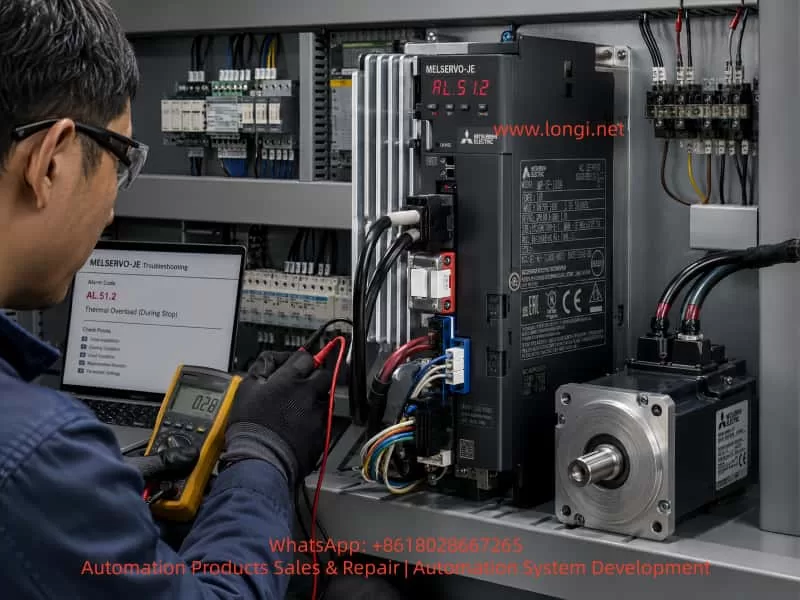

Technician using a multimeter and diagnostic laptop to troubleshoot a Mitsubishi MELSERVO-JE servo drive displaying the AL.51.2 stopped-state thermal overload alarm inside an industrial control cabinet.

1. What AL.51.2 Actually Means

A stopped servo motor is not necessarily an electrically inactive motor.

When the Servo ON signal remains active, the servo amplifier continues to control the motor even when the commanded speed is zero. The amplifier constantly compares the commanded position with the encoder feedback position. If an external force attempts to move the motor shaft, or if the actual position differs from the target position, the amplifier generates corrective torque.

For example, consider a vertical lifting axis. When the axis reaches its commanded position, the motor speed becomes zero, but gravity continues to pull the load downward. If the brake has not yet engaged, the servo motor must produce holding torque to prevent the load from falling.

The amplifier continuously evaluates factors such as:

  • Motor output current
  • Duration of high current
  • Motor rated capacity
  • Amplifier rated capacity
  • Zero-speed operating condition
  • Load ratio during acceleration, deceleration, and holding
  • Thermal accumulation in the power stage
  • Estimated motor winding temperature

When high current continues for too long while the motor is stopped, the electronic thermal protection function activates and generates AL.51.2.

The essential meaning of the alarm is therefore:

The motor is stopped, but the servo system is still producing abnormally high torque and current.


2. Why a Servo Motor Can Overload While Stopped

A servo system usually contains three nested control loops:

  1. Current loop
  2. Speed loop
  3. Position loop

When the motor reaches its target position, the position loop remains active. If the encoder detects even a small position error, the controller creates a speed correction command. The speed loop then produces a torque command, and the current loop regulates the three-phase current supplied to the motor.

Under normal conditions, only a moderate current is needed to hold position. However, if the motor cannot move or if the load continuously applies a large external force, the amplifier increases torque.

High current at zero or near-zero speed is especially dangerous because motor cooling is often poor in this condition. Motor copper loss follows the relationship:

[
P_{\text{Cu}}=I^2R
]

Where:

  • (P_{\text{Cu}}) is winding copper loss
  • (I) is motor current
  • (R) is winding resistance

If motor current doubles, copper loss theoretically increases by a factor of four. For this reason, a stalled servo motor may overheat much faster than expected, even if the motor housing does not immediately feel hot.

Typical conditions that produce high current while stopped include:

  • The machine has reached a mechanical end stop
  • A ballscrew, guide rail, or gearbox is jammed
  • The electromagnetic brake has not released
  • A vertical load is too heavy
  • The encoder feedback is unstable or incorrect
  • U, V, and W motor phases are incorrectly connected
  • The motor is oscillating around the holding position
  • Servo gains are too high
  • Load inertia is excessive
  • The motor is undersized
  • A coupling or bearing is seized
  • The controller continues issuing position commands after the mechanism has stopped
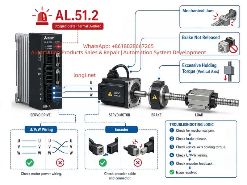
Technical troubleshooting diagram for Mitsubishi MR-JE servo alarm AL.51.2, showing mechanical jamming, unreleased motor brake, excessive vertical-axis holding torque, incorrect U/V/W wiring, and encoder connection faults.

3. Difference Between AL.51.2 and General Running Overload

The most important diagnostic feature of AL.51.2 is that it occurs under a stopped or zero-speed condition.

If an overload alarm occurs during high-speed operation, acceleration, or repeated production cycles, the main areas to inspect are normally:

  • Excessive moving load
  • Acceleration time too short
  • Deceleration time too short
  • Excessive load inertia
  • Increased mechanical friction
  • Insufficient motor capacity

If the alarm occurs after positioning is complete, immediately after Servo ON, or while the shaft is holding still, priority should be given to:

  • Mechanical blockage
  • Brake release failure
  • Excessive holding torque
  • Vertical-axis imbalance
  • Zero-speed oscillation
  • Incorrect motor wiring
  • Encoder feedback problems
  • Incorrect servo parameter settings

The time at which the alarm appears is often more useful than the alarm code alone.


4. Mechanical Seizure Is the Most Common Cause

Mechanical blockage is one of the most frequent causes of AL.51.2.

Typical mechanical problems include:

  • Seized ballscrew
  • Dry or damaged linear guide
  • Broken linear bearing
  • Worn gearbox
  • Damaged gearbox gear
  • Misaligned coupling
  • Broken coupling insert
  • Overtightened belt
  • Seized motor bearing
  • Foreign material inside the mechanism
  • Workpiece interference
  • Clamp or cylinder not retracted
  • Machine axis hitting a hard stop
  • Vertical-axis counterweight failure
  • Incorrect mechanical assembly alignment

When the machine cannot move but the controller continues to command movement, the position error increases. The servo amplifier responds by increasing torque.

Typical field symptoms include:

  • The motor produces a low-frequency humming sound
  • The shaft does not rotate
  • The motor heats quickly
  • The coupling or ballscrew vibrates
  • The torque monitor approaches 100%
  • Position deviation or droop pulses continue increasing
  • The alarm appears a few seconds after the axis stops
  • The same movement always produces the same alarm

The most effective diagnostic method is to disconnect the motor from the load.

After removing the coupling, belt, or gearbox connection, inspect the motor and the mechanical mechanism separately.

The machine mechanism should move smoothly without:

  • Hard points
  • Sudden resistance
  • Metallic noise
  • Intermittent locking
  • Excessive friction
  • Abnormal backlash

If the servo motor operates normally after being disconnected from the load, the problem is almost certainly on the mechanical side.


5. Failure of the Electromagnetic Brake to Release

Servo motors with holding brakes are commonly used on:

  • Vertical axes
  • Hoists
  • Lifting platforms
  • Z axes
  • Stackers
  • Robot lifting mechanisms
  • Anti-drop systems

The motor brake is a holding brake. Its purpose is to maintain load position after the servo is disabled or power is removed. It is not intended to stop a moving axis during normal operation.

A correct brake release sequence is generally:

  1. Servo amplifier powers up
  2. Amplifier becomes ready
  3. Servo ON turns on
  4. Motor establishes holding torque
  5. Brake power is applied
  6. Brake is allowed enough time to release
  7. Motion command is issued

If the brake does not release, the servo amplifier attempts to rotate the motor against the engaged brake. The motor remains stationary while current rises rapidly.

Common brake-related causes include:

  • Brake coil has no rated voltage
  • Brake power supply capacity is insufficient
  • Brake rectifier is damaged
  • Relay contacts are burned
  • Contactor contacts are resistive
  • Brake coil is open circuit
  • Brake mechanism is rusted or mechanically stuck
  • PLC brake logic is incorrect
  • Motion starts before the brake is fully released
  • Brake release delay is too short
  • Brake supply voltage drops under load

Do not judge brake operation only by observing the PLC output indicator or hearing the relay click. A relay may energize while its contacts fail to deliver voltage.

The correct check is to measure the actual voltage directly at the brake coil terminals.

On a vertical axis, always secure the load with a mechanical support, hoist, safety block, or other anti-drop device before releasing the brake.


6. U, V, and W Motor Cable Problems

The MR-JE servo amplifier controls the servo motor through the U, V, and W output phases. Any open circuit, incorrect phase connection, loose terminal, or intermittent cable fault may produce abnormal torque and high current.

Typical problems include:

  • Loose U, V, or W terminal
  • Motor connector not fully inserted
  • Recessed connector pin
  • Burned power connector
  • Broken conductor inside a drag-chain cable
  • Cable crushed by moving machinery
  • Corroded terminal
  • Incorrect phase connection after repair
  • Wrong motor cable
  • Partial motor winding open circuit

Unlike a standard induction motor, a servo motor must not have two phases exchanged simply to reverse direction. The motor phase sequence must correspond correctly to the encoder commutation data.

If U, V, and W are incorrectly connected, the electromagnetic field produced by the amplifier will not match the encoder rotor position feedback. This may result in:

  • Violent vibration
  • Sudden shaft movement
  • Failure to rotate
  • High current
  • Humming
  • Immediate overload
  • AL.51.2 after a short delay

Intermittent cable faults are particularly difficult to locate. A conductor may make contact in one cable position and open in another.

Typical signs of an intermittent motor cable include:

  • Alarm occurs only at one machine position
  • Moving the cable changes the symptom
  • Cold operation is normal but warm operation fails
  • Reconnecting the plug temporarily restores operation
  • Fault appears randomly during axis travel

With power completely disconnected, measure the resistance between:

  • U and V
  • V and W
  • W and U

The three values should be approximately equal.

Servo motor winding resistance is normally low, so first short the meter probes together and record the lead resistance. Subtract this value from the measured winding resistance where necessary.

Abnormal results include:

  • One pair reads open circuit
  • One pair is significantly higher than the others
  • One pair is significantly lower than the others
  • Resistance changes when the cable is moved

These results indicate a cable or motor winding fault.


7. Encoder Feedback Problems

The servo amplifier relies on encoder feedback to determine:

  • Rotor position
  • Actual speed
  • Shaft direction
  • Position deviation
  • Commutation timing

If the encoder signal is unstable, incorrect, or intermittent, the amplifier may believe that the motor is not reaching the commanded position. It then increases output torque in an attempt to correct the error.

Possible encoder-related causes include:

  • Loose encoder connector
  • Connector latch not secured
  • Bent pin
  • Recessed pin
  • Damaged shield
  • Broken conductor
  • Cable damaged inside the drag chain
  • Encoder cable routed parallel to motor power cables
  • Poor cabinet grounding
  • Excessive electrical noise
  • Incorrect motor model
  • Incompatible encoder cable
  • Encoder hardware failure

Typical symptoms include:

  • Motor trembles while stopped
  • Torque monitor alternates rapidly between positive and negative
  • Encoder position is unstable
  • Actual speed fluctuates around zero
  • High-frequency noise from the motor
  • Servo ON immediately produces abnormal current
  • Position deviation changes without a motion command

A weak or intermittent encoder signal may not always generate a dedicated encoder alarm. If feedback remains partially valid, the first visible symptom may be unstable holding control and AL.51.2.


8. Zero-Speed Oscillation and Excessive Servo Gain

In some machines, the motor appears stationary to the eye but is actually oscillating with very small amplitude and high frequency.

Possible causes include:

  • Position loop gain too high
  • Speed loop gain too high
  • Automatic tuning response level too high
  • Poor mechanical rigidity
  • Flexible coupling
  • Large gearbox backlash
  • Ballscrew backlash
  • Resonance not properly suppressed
  • Loose motor mounting
  • Excessive load inertia variation
  • Elastic deformation in the mechanism
  • Incorrect tuning after mechanical modification

During zero-speed oscillation, the average speed may be close to zero, but the motor continuously produces alternating positive and negative torque. The current can remain high enough to create thermal accumulation.

Typical signs include:

  • High-pitched motor noise at standstill
  • Fine vibration felt on the motor frame
  • Torque monitor rapidly alternates
  • Actual speed fluctuates near zero
  • Encoder position changes slightly and continuously
  • Noise disappears immediately when Servo ON is removed
  • Lower gain reduces or eliminates the alarm

The correct solution is not to reduce gain blindly. Excessive gain may be a symptom of mechanical looseness or resonance.

A better procedure is:

  1. Tighten the motor base and mechanical joints
  2. Check coupling condition
  3. Inspect gearbox and ballscrew backlash
  4. Verify load inertia
  5. Repeat automatic tuning
  6. Reduce response level moderately
  7. Apply resonance suppression filters
  8. Review torque and speed waveforms
  9. Optimize position and speed loop gains gradually

9. Excessive Holding Torque on a Vertical Axis

Vertical-axis systems are especially vulnerable to AL.51.2.

Examples include:

  • Lifting platforms
  • Robot Z axes
  • Stacker cranes
  • Press lifting mechanisms
  • Vertical positioning tables
  • Tool-head lifting systems

If the system has no counterweight, or if the counterweight no longer matches the actual load, the motor must continuously oppose gravity.

Common causes include:

  • Increased payload
  • Heavier tooling installed
  • Counterweight cable failure
  • Pneumatic balance cylinder leakage
  • Spring balancer failure
  • Gearbox efficiency deterioration
  • Brake does not engage after stopping
  • Motor capacity too small
  • Incorrect gear ratio
  • Poor ballscrew lubrication

A proper stopping sequence for a vertical axis is generally:

  1. Decelerate to zero speed
  2. Hold the load with servo torque
  3. Apply the brake
  4. Wait until the brake is fully engaged
  5. Remove Servo ON if required

If the motor remains enabled for a long time before the brake is applied, holding current may remain high.

If the brake is applied too early, before the axis reaches zero speed, the brake may be damaged. If Servo ON is removed before the brake fully engages, the load may drop.

Brake timing must therefore be coordinated carefully.


10. Motor Capacity and Load Inertia Problems

Servo motor selection must consider more than rated power.

Important design factors include:

  • Continuous load torque
  • Peak torque
  • Acceleration torque
  • Deceleration torque
  • Holding torque
  • Load inertia
  • Motor inertia
  • Gear ratio
  • Motion cycle
  • Vertical gravity load
  • Ambient temperature
  • Cooling conditions
  • Repetition rate

A machine may operate normally during commissioning without a workpiece but generate AL.51.2 after tooling, product, or an additional fixture is installed.

Excessive load inertia requires large torque during acceleration and deceleration. Even if the alarm appears after the motor stops, thermal accumulation may have already developed during repeated motion cycles.

If the peak load ratio and effective load ratio remain high, consider:

  • Increasing acceleration time
  • Increasing deceleration time
  • Reducing payload
  • Improving counterbalance
  • Changing gear ratio
  • Reducing mechanical friction
  • Increasing motor capacity
  • Increasing amplifier capacity
  • Reducing cycle frequency
  • Recalculating the inertia ratio

Increasing the torque limit is not a proper solution to an undersized motor. It may allow the mechanism to move temporarily but increases the risk of motor and amplifier damage.


11. Correct Field Diagnostic Sequence

AL.51.2 should be diagnosed in a structured order:

Mechanical system first, wiring second, parameters third, hardware last.

This approach minimizes unnecessary part replacement.

Step 1: Record the Exact Alarm Timing

Determine whether the alarm appears:

  • Immediately after power-up
  • At Servo ON
  • When the brake is released
  • When motion starts
  • During acceleration
  • During deceleration
  • After reaching position
  • Several seconds after stopping
  • After long production operation
  • Only at one mechanical position
  • After a tooling or load change

This timing information narrows the diagnostic direction.

Step 2: Inspect the Mechanical Load

With power removed and the machine secured, disconnect the motor from the load if possible.

Check whether the mechanism moves smoothly.

For a vertical axis, never release the brake without securing the load.

Step 3: Inspect Motor Temperature and Smell

Check for:

  • Unusually hot motor housing
  • Burned insulation smell
  • Discolored connectors
  • Hot power terminals
  • Abnormal drive heatsink temperature

A cool motor housing does not rule out thermal overload because internal winding temperature may rise before heat reaches the housing.

Step 4: Check Brake Voltage

Measure voltage directly at the brake coil.

Also verify:

  • Brake release delay
  • Brake engage delay
  • Relay contact condition
  • Voltage stability under load

Step 5: Check Motor Power Wiring

Inspect:

  • U, V, W terminals
  • Motor connector
  • Cable shield
  • Drag-chain section
  • Burned pins
  • Loose screws
  • Cable continuity

Step 6: Measure Winding Resistance

Measure U-V, V-W, and W-U.

The values should be balanced.

Step 7: Check Insulation to Ground

Disconnect the motor cable completely from the servo amplifier before using an insulation resistance tester.

Measure:

  • U to motor frame
  • V to motor frame
  • W to motor frame

Never apply insulation tester voltage to the amplifier output terminals.

Step 8: Inspect Encoder Wiring

Check connector locking, pin condition, shield grounding, cable routing, and cable continuity.

Where possible, test with a known-good encoder cable.

Step 9: Run the Motor Without Load

Disconnect the coupling and run the motor at low speed and short travel.

If unloaded operation is normal, the mechanical system is the likely cause.

If AL.51.2 remains, inspect the motor, cable, encoder, and amplifier.


12. Using MR Configurator2 for Diagnosis

MR Configurator2 is an important diagnostic tool for Mitsubishi servo systems.

Useful monitored values include:

  • Motor speed
  • Command speed
  • Motor torque
  • Peak load ratio
  • Effective load ratio
  • Encoder position
  • Command position
  • Position deviation
  • Droop pulses
  • Servo status
  • Input signals
  • Output signals
  • Brake output state

Condition 1: Speed Is Zero, Torque Is Near 100%

Likely causes:

  • Mechanical seizure
  • Brake not released
  • Mechanical end stop
  • Excessive vertical load
  • Motor phase problem

Condition 2: Torque Alternates Rapidly at Standstill

Likely causes:

  • Excessive gain
  • Mechanical resonance
  • Loose coupling
  • Gearbox backlash
  • Encoder instability

Condition 3: Command Speed Exists, Actual Speed Remains Zero

Likely causes:

  • Brake locked
  • Mechanism jammed
  • U, V, W phase loss
  • Incorrect motor wiring
  • Encoder problem

Condition 4: Position Deviation Continues Increasing

The controller is still requesting movement, but the motor cannot reach the target.

Likely causes:

  • Mechanical blockage
  • Wrong direction
  • Brake not released
  • Insufficient torque
  • Excessive load

Condition 5: High Holding Torque After Positioning

Inspect:

  • Vertical load
  • Counterweight
  • Brake engagement timing
  • Friction
  • Motor capacity
  • Gear ratio

Saving an oscilloscope trace before the alarm occurs is often the fastest way to identify the root cause.


13. Distinguishing Motor Failure from Amplifier Failure

Only consider component failure after the mechanical system, cables, brake, encoder, and parameters have been checked.

Possible motor faults include:

  • Partial winding short circuit
  • Open winding
  • Moisture ingress
  • Insulation deterioration
  • Seized bearing
  • Damaged brake
  • Encoder failure
  • Rotor damage

Possible servo amplifier faults include:

  • IGBT power module failure
  • Current detection circuit drift
  • Missing output phase
  • Gate driver board failure
  • Unstable internal power supply
  • Control board processing error
  • Cooling fan failure
  • Temperature detection circuit fault

The most reliable method is substitution testing.

Under strictly matched conditions, test with:

  • Known-good motor
  • Known-good motor power cable
  • Known-good encoder cable
  • Known-good servo amplifier

Before replacing the amplifier, back up all parameters.

The replacement must match:

  • Voltage class
  • Rated capacity
  • Motor series
  • Motor encoder type
  • Control mode
  • Parameter settings

If the alarm disappears after replacing the amplifier, the original amplifier is likely defective.

If the alarm disappears after replacing the motor, the original motor, encoder, brake, or winding is likely defective.


14. Alarm Reset and Safe Restart Procedure

AL.51.2 should not be repeatedly reset without investigation.

A safe restart procedure is:

  1. Stop the motion command
  2. Remove Servo ON
  3. Switch off main power
  4. Switch off control power if required
  5. Wait for the DC bus to discharge
  6. Correct the mechanical, wiring, brake, or parameter issue
  7. Allow the motor and amplifier to cool
  8. Restore power
  9. Test without load if possible
  10. Use low speed and short travel
  11. Monitor torque and load ratio
  12. Gradually restore normal production settings

Avoid the following unsafe practices:

  • Repeated alarm reset
  • Disabling the alarm output
  • Raising torque limits without analysis
  • Long-duration stall testing
  • Operating against an engaged brake
  • Increasing current to overcome a jam
  • Using mismatched motor parameters
  • Running before checking mechanical interference

15. Typical Case Study: Vertical Axis Overload at Standstill

A machine used an MR-JE servo system for a vertical lifting axis. The system operated normally without tooling. After a heavier fixture was installed, the axis moved to position correctly but generated AL.51.2 approximately ten seconds after stopping.

Inspection showed:

  • No obvious abnormality during motion
  • Actual motor speed was zero after positioning
  • Torque remained high during standstill
  • Brake engaged only after Servo OFF
  • Counterweight had not been adjusted for the heavier fixture

The servo motor was therefore supporting almost the entire vertical load while stopped. The sustained holding current caused the electronic thermal overload model to trip.

Corrective actions included:

  • Rebalancing the counterweight
  • Modifying brake timing
  • Applying the brake shortly after zero speed was confirmed
  • Increasing brake confirmation delay
  • Reviewing acceleration and deceleration
  • Checking motor capacity margin
  • Monitoring effective load ratio

After correction, standstill torque decreased significantly and AL.51.2 no longer occurred.


16. Typical Case Study: Incorrect U-V-W Connection

After a servo motor replacement, a machine produced strong vibration immediately after Servo ON and then generated AL.51.2.

The motor cable had been reconnected with the wrong phase sequence.

Because the magnetic field produced by the amplifier did not correspond to the rotor position reported by the encoder, the amplifier continuously applied incorrect correction torque. The motor did not rotate normally and current increased rapidly.

After restoring the correct U, V, and W connections, the motor operated normally.

This case demonstrates that servo motor phase wiring must never be treated like ordinary induction motor wiring.


17. Preventive Maintenance Measures

Preventing AL.51.2 requires attention to mechanical condition, electrical connections, servo parameters, and operating data.

Mechanical Maintenance

  • Lubricate ballscrews and linear guides
  • Inspect bearings and gearboxes
  • Check coupling alignment
  • Remove foreign objects from travel areas
  • Inspect hard stops and limit mechanisms
  • Check vertical-axis counterweights
  • Tighten motor mounts and mechanical joints
  • Check belts and pulleys
  • Monitor abnormal friction

Electrical Maintenance

  • Tighten U, V, and W terminals
  • Inspect power connectors for heat damage
  • Check drag-chain cable fatigue
  • Confirm encoder connector locking
  • Maintain proper shielding and grounding
  • Separate encoder cables from power cables
  • Inspect brake relays and contactors
  • Verify brake power supply voltage

Parameter Maintenance

  • Use realistic acceleration and deceleration times
  • Tune gain according to actual mechanical rigidity
  • Avoid unnecessarily high response levels
  • Use automatic tuning where appropriate
  • Apply resonance suppression filters
  • Set reasonable torque limits
  • Back up parameters
  • Reevaluate motor sizing after load changes

Monitoring and Records

  • Record peak load ratio
  • Record effective load ratio
  • Monitor standstill torque
  • Save alarm history
  • Record the machine position at which the alarm occurs
  • Record whether the alarm occurs during motion or after stopping
  • Test vertical-axis brake operation periodically

18. Practical Troubleshooting Summary

When a Mitsubishi MR-JE servo amplifier displays AL.51.2, the following checks should be prioritized:

  1. Check whether the mechanism is jammed or against a hard stop.
  2. Check whether the electromagnetic brake is actually releasing.
  3. Verify U, V, and W motor wiring.
  4. Inspect the motor cable for open circuits or intermittent conductors.
  5. Inspect the encoder connector and encoder cable.
  6. Disconnect the mechanical load and run the motor unloaded.
  7. Monitor torque, speed, and position deviation with MR Configurator2.
  8. Check for zero-speed vibration or high-frequency noise.
  9. Review vertical-axis holding torque and brake timing.
  10. Verify motor capacity and load inertia.
  11. Perform substitution testing only after external causes are eliminated.

The three most valuable field tests are:

  • Disconnect the coupling and run the motor unloaded.
  • Measure brake voltage directly at the brake coil.
  • Capture torque, speed, and position-deviation waveforms with MR Configurator2.

Conclusion

The Mitsubishi MR-JE AL.51.2 alarm indicates that the servo motor is stopped, holding position, or mechanically stalled while the servo amplifier continues to supply excessive current. The amplifier’s electronic thermal protection determines that the motor or power stage has entered an unsafe overload condition.

The most common causes are:

  • Mechanical seizure
  • Mechanical end-stop collision
  • Brake release failure
  • Excessive vertical-axis holding torque
  • Incorrect or open U-V-W wiring
  • Encoder feedback instability
  • Zero-speed oscillation
  • Excessive servo gain
  • Oversized load inertia
  • Undersized motor
  • Motor or amplifier hardware failure

The alarm should be diagnosed by first identifying the exact operating stage at which it occurs. The recommended sequence is:

Mechanical inspection → brake inspection → motor power wiring → encoder system → servo parameters → motor and amplifier hardware

In many field cases, the servo amplifier itself is not the root cause. Replacing the amplifier before checking the mechanical load, brake circuit, motor wiring, and encoder system often leads to unnecessary cost and repeated failure.

The key diagnostic question is:

Why is the motor still producing high torque while its speed is zero?

Once that question is answered through mechanical inspection, electrical measurement, and waveform monitoring, the cause of AL.51.2 can usually be identified accurately and repaired safely.
Posted on

Mitsubishi FR-F840 E.UVT Undervoltage Fault Troubleshooting Guide: A Complete Diagnostic Approach from DC Bus Charging to Voltage Detection Circuit Failure

Introduction

In industrial automation systems, variable frequency drives (VFDs) are widely used for controlling motors in applications such as pumps, fans, compressors, conveyors, machine tools, and production equipment. As the operating environment becomes more demanding, VFDs are exposed to voltage fluctuations, temperature stress, dust contamination, and long-term electrical aging.

When a drive displays a fault code, many technicians immediately associate the alarm name with the failure location. For example, an overcurrent alarm is often considered an IGBT failure, while an undervoltage alarm is assumed to be caused by insufficient input voltage.

However, modern industrial VFDs use complex protection and monitoring systems. A fault code usually represents the condition detected by the control system, not necessarily the exact failed component.

A typical example is the Mitsubishi FR-F840-00620-2-60, a 400V-class high-power inverter with approximately 62A rated output current and 30kW motor capacity. In field repair work, this model may experience the E.UVT (Undervoltage Trip) alarm. Especially when the drive reports E.UVT immediately after power-on, the actual cause is often not simply an external power supply problem.

Possible causes include:

  • Three-phase input abnormality;
  • Rectifier circuit failure;
  • DC bus charging problems;
  • Pre-charge resistor or relay failure;
  • DC bus voltage detection circuit malfunction;
  • Control power instability;
  • Main control board sampling errors.

This article provides a systematic troubleshooting method for Mitsubishi FR-F840 E.UVT faults, especially for cases where the inverter alarms immediately after energization and the power module has already been confirmed to be normal.


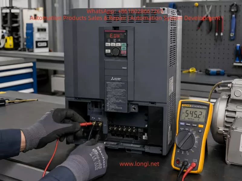
Mitsubishi FR-F840 inverter E.UVT undervoltage fault troubleshooting with DC bus voltage measurement using a digital multimeter

1. Basic Structure of Mitsubishi FR-F840-00620-2-60

Before troubleshooting an undervoltage fault, it is necessary to understand the internal power structure of the inverter.

The Mitsubishi FR-F840 belongs to the F800 series, designed mainly for industrial fan, pump, HVAC, and general-purpose drive applications.

The basic energy conversion process is:

Three-phase AC input

R / S / T

↓

Input protection and filtering

↓

Rectifier bridge

↓

DC bus

P(+) / N(-)

↓

DC capacitors

↓

IGBT inverter module

↓

U / V / W output

↓

Motor

The main functions of each section are:

Rectifier section

Converts three-phase AC voltage into DC voltage.

DC bus section

Stores energy and stabilizes the DC voltage.

IGBT inverter section

Converts DC voltage into variable-frequency AC output for motor control.

Control board

Responsible for:

  • Voltage monitoring;
  • Current detection;
  • Protection logic;
  • PWM generation;
  • Fault judgment.

The E.UVT fault is mainly related to the section:

AC input
↓
Rectification
↓
DC bus charging
↓
DC voltage detection

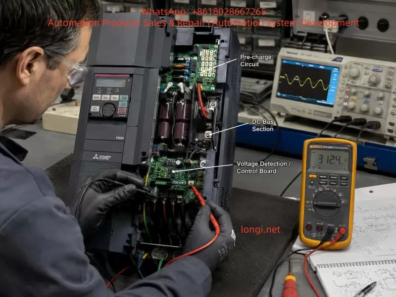
Mitsubishi FR-F840 variable frequency drive repair showing pre-charge circuit, DC bus section, and voltage detection control board inspection during E.UVT fault diagnosis

2. What Does E.UVT Mean?

E.UVT stands for:

Undervoltage Trip

It means:

The inverter has detected that the DC bus voltage has dropped below the allowable operating threshold and has activated protection.

For a 400V-class inverter:

The approximate DC bus voltage can be calculated as:

DC voltage ≈ AC voltage × 1.414

For example:

380VAC × 1.414 ≈ 537VDC

Normally, the FR-F840 DC bus voltage should be approximately:

500–560VDC

depending on the actual input voltage.

If the DC bus voltage decreases significantly, for example:

300VDC

or lower, the control system determines that the inverter cannot safely drive the IGBT section and triggers:

E.UVT

3. Why Is “Immediate E.UVT After Power-On” Important?

The timing of the fault provides valuable diagnostic information.

There are three typical situations:


Case 1: E.UVT During Normal Operation

Example:

The inverter runs normally for several minutes and then suddenly trips.

Possible causes:

  • Utility voltage fluctuation;
  • Insufficient transformer capacity;
  • Large load startup on the same power network;
  • Loose input contactor;
  • Poor cable connection.

Case 2: E.UVT During Acceleration

Possible causes:

  • Excessive motor load;
  • Acceleration time too short;
  • DC regenerative energy problems;
  • Weak power supply.

Case 3: E.UVT Immediately After Power-On

This is the most important condition.

At this moment:

  • The motor has not started;
  • The IGBT output is inactive;
  • Load influence is minimal.

Therefore, the problem is usually located in the power supply establishment and voltage detection circuits.

The main inspection areas are:

  1. AC input;
  2. Rectifier bridge;
  3. Pre-charge circuit;
  4. DC bus capacitors;
  5. DC voltage detection circuit.

4. Step-by-Step Troubleshooting Procedure

Step 1: Check Three-Phase Input Voltage

First measure:

R-S
S-T
T-R

Normal values:

380–440VAC

The three phases should be balanced.

Example:

Normal:

R-S = 402V
S-T = 401V
T-R = 403V

Abnormal:

R-S = 400V
S-T = 395V
T-R = 250V

Possible causes:

  • Phase loss;
  • Damaged contactor;
  • Loose terminal;
  • Power supply problem.

5. Step 2: Measure DC Bus Voltage

This is the most important measurement.

Measure between:

P(+)

and

N(-)

Expected value:

Approximately:

500–560VDC

The result determines the troubleshooting direction.


Situation A: DC Bus Voltage Does Not Build Up

Example:

P-N = 50VDC

The inverter cannot establish the DC bus.

Possible causes:


1. Rectifier Bridge Failure

The IGBT module may be normal, but the rectifier section can still fail.

Possible faults:

  • Open rectifier diode;
  • Damaged rectifier module;
  • Input phase failure;
  • Internal connection problem.

Important:

A normal IGBT does not mean the complete power section is normal.

The rectifier and inverter sections are independent.


2. Pre-Charge Circuit Failure

Large-capacity inverters cannot directly charge large DC capacitors because the initial charging current would be extremely high.

Therefore, they use a pre-charge circuit:

AC input

↓

Rectifier bridge

↓

Pre-charge resistor

↓

DC capacitors

↓

Bypass relay/contactor

↓

Normal operation

If any of the following fail:

  • Pre-charge resistor open;
  • Relay does not activate;
  • Relay contact burned;
  • Drive circuit failure;

the DC bus cannot charge correctly, resulting in E.UVT.


Situation B: DC Bus Voltage Is Normal but E.UVT Still Appears

This situation is very common during professional repairs.

Example measurement:

P-N = 530VDC

but the inverter still displays:

E.UVT

This means:

The actual DC voltage is normal, but the control system believes the voltage is too low.

The suspected area is:

DC bus voltage detection circuit.


6. DC Bus Voltage Detection Principle

The CPU cannot directly measure 500VDC.

Therefore, the inverter uses a voltage detection circuit:

DC 500V

↓

High-voltage resistor divider

↓

Isolation circuit

↓

ADC sampling

↓

CPU calculation

↓

Protection judgment

If this circuit fails:

Actual voltage:

530VDC

Detection result:

200VDC

The CPU will incorrectly trigger:

E.UVT

Common Detection Circuit Failures

1. High-Voltage Resistor Drift

High-voltage resistors operate continuously under electrical stress.

After years of operation:

  • Resistance increases;
  • Resistance decreases;
  • Internal cracks occur.

The voltage division ratio changes, causing incorrect measurement.


2. Optocoupler Aging

Some inverter designs use isolation components.

After long operation:

  • Optical transmission efficiency decreases;
  • Signal amplitude becomes incorrect.

3. Detection IC Failure

Possible problems:

  • ADC input abnormality;
  • Operational amplifier damage;
  • Reference voltage failure.

7. Control Power Supply Problems

The control board requires stable low-voltage supplies.

Important rails include:

+5V Power Supply

Used by:

  • CPU;
  • Digital circuits;
  • Memory.

If:

5V drops to 4.5V

the CPU may misjudge voltage signals.


+15V Power Supply

Used for:

  • Gate drive circuits;
  • Analog detection circuits.

+24V Power Supply

Used for:

  • Relays;
  • External control interfaces.

Unstable control power can cause:

  • E.UVT;
  • CPU errors;
  • Communication faults.

8. Common Repair Mistakes

Mistake 1: Replacing the IGBT Immediately

Many technicians see a power-related alarm and replace the IGBT module.

This is often unnecessary.

The IGBT may be completely normal.


Mistake 2: Only Measuring Input Voltage

Checking:

R/S/T voltage normal

does not prove the inverter is healthy.

The technician must also check:

P-N DC bus voltage

because the failure may exist in:

  • Rectification;
  • Pre-charge;
  • Voltage detection.

Mistake 3: Assuming a Normal Power Module Means the Main Circuit Is Good

The main power system includes:

  • Rectifier;
  • DC capacitors;
  • Pre-charge circuit;
  • Voltage detection;
  • IGBT inverter.

All sections must be verified.


9. Example Repair Case: FR-F840-00620-2-60 Immediate E.UVT

Equipment

Model:

Mitsubishi FR-F840-00620-2-60

Power:

30kW

Fault:

E.UVT immediately after power-on

Inspection Process

Step 1

Three-phase input voltage checked.

Result:

Normal.

External power supply was excluded.


Step 2

IGBT module checked.

Result:

Normal.

Power module failure was excluded.


Step 3

DC bus measured.

Result:

Approximately:

530VDC

The DC bus was successfully established.


Step 4

Voltage detection circuit inspected.

Finding:

The DC voltage feedback signal was abnormal.

Cause:

High-voltage divider components had drifted from their original values.

After repairing the detection circuit:

The inverter returned to normal operation.


This case demonstrates an important principle:

An undervoltage alarm does not always mean the actual voltage is low.

The failure may exist in the measurement system.


10. Recommended Diagnostic Strategy for High-Power VFD Repair

For inverters above 30kW, technicians should follow a fixed troubleshooting sequence:

Confirm fault code

↓

Analyze fault timing

↓

Measure AC input

↓

Measure DC bus voltage

↓

Check charging circuit

↓

Check voltage detection

↓

Check control power supply

↓

Repair and test

Avoid unnecessary replacement of expensive components such as:

  • IGBT modules;
  • Control boards;
  • Main boards.

The correct approach is:

Measure first, diagnose second, replace components last.


Conclusion

For Mitsubishi FR-F840-00620-2-60 inverters displaying E.UVT undervoltage faults, especially when the alarm occurs immediately after power-on, the troubleshooting focus should not be limited to the external power supply.

The correct diagnostic sequence is:

  1. Verify three-phase input voltage;
  2. Measure DC bus voltage;
  3. Check rectifier and pre-charge circuits;
  4. Verify DC voltage feedback detection;
  5. Check control board power supplies.

When the power module has already been confirmed normal, technicians should pay special attention to:

  • DC bus voltage detection circuits;
  • Pre-charge charging circuits;
  • Control board sampling circuits.

The key principle of industrial inverter troubleshooting is:

A fault code shows what the drive detected, not necessarily where the failure occurred.

Only by combining electrical measurements, circuit understanding, and systematic analysis can technicians accurately locate faults, reduce unnecessary component replacement, and improve repair efficiency.

Posted on

Mitsubishi FR-A740 Inverter E.UVT Undervoltage False Alarm Mechanism Analysis and Power Detection System Fault Localization Method (Based on 570V DC Bus Case Study)

1. Introduction: Engineering Significance of E.UVT Alarms and Misjudgment Phenomenon

In industrial inverter systems, undervoltage protection (UVT – Undervoltage Trip) is one of the most fundamental protection mechanisms, but also one of the most frequently misdiagnosed faults. For the Mitsubishi FR-A740 series vector control inverter, the E.UVT alarm is designed to protect the IGBT power module and control circuits from abnormal operation under insufficient DC bus voltage conditions.

However, in real-world maintenance cases, a typical contradiction often occurs:

The DC bus voltage is normal (e.g., 540–580V), yet the inverter still reports an E.UVT fault.

This document analyzes a real engineering case (380V input, 570V DC bus normal, persistent E.UVT alarm) and provides a systematic breakdown of the fault mechanism across three layers: power architecture, detection circuit, and control logic, along with a practical troubleshooting methodology.


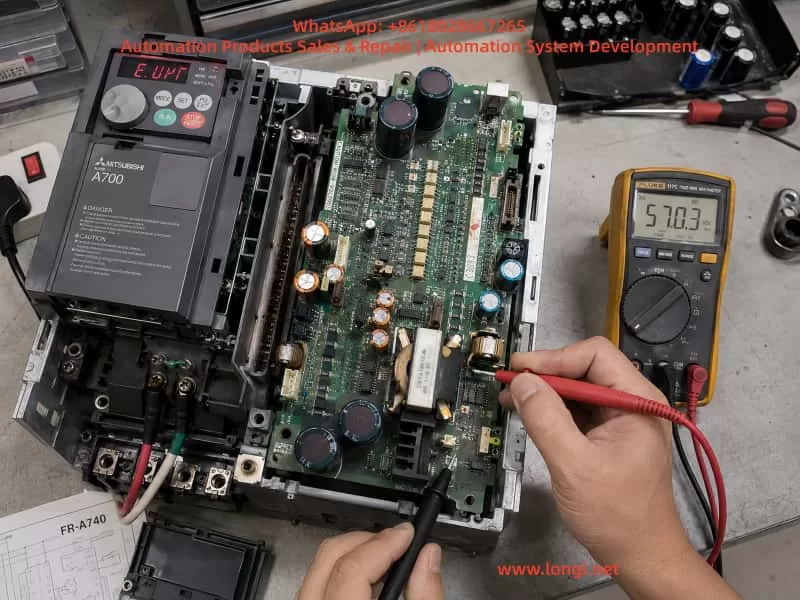
Technician diagnosing a Mitsubishi FR-A740 7.5kW inverter with E.UVT undervoltage alarm using a digital multimeter measuring 570V DC on the power/control board inside an open drive cabinet during industrial maintenance.

2. Power System Architecture and UVT Trigger Logic in FR-A740

2.1 Main Circuit Structure

The FR-A740 power path is structured as follows:

Three-phase 380–480VAC input
        ↓
Rectifier bridge (6-pulse conversion)
        ↓
DC bus capacitor bank (DC LINK ~510–580V)
        ↓
Pre-charge resistor + bypass relay
        ↓
IGBT inverter module

Under normal conditions:

ParameterNormal Range
AC Input380–480V
DC Bus510–580V
UVT Threshold~380–400V

2.2 UVT Is Not a Direct Voltage Measurement

The E.UVT fault is not triggered by a single ADC measurement of DC voltage. Instead, it is determined by a combination of multiple system signals:

  1. DC bus divided voltage sensing signal
  2. Control power supply stability (SMPS output)
  3. CPU power-on initialization status (Power Good signal)

Therefore:

UVT ≠ Simple undervoltage detection
UVT = Power system instability or incomplete initialization


3. Engineering Contradiction in This Case

Observed parameters:

  • Input: 380V normal
  • DC bus: 570V normal
  • Fault: Persistent E.UVT alarm
  • Power board: Already inspected with visible aging signs

Key contradiction

If UVT were truly valid, the DC bus voltage should be below ~400V.
However, the measured value is 570V.

Therefore:

The fault is not in the power circuit, but in the detection or control circuit layer.


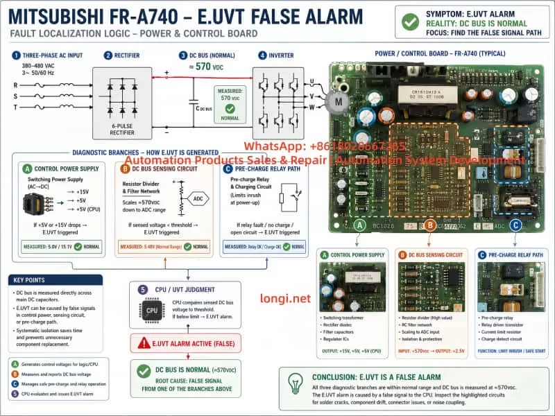
4. Four Primary Failure Mechanism Models of E.UVT Misalarm


4.1 Control Power Supply Transient Drop Model (Highest Probability)

Structure

The internal SMPS provides:

  • +5V CPU logic supply
  • +15V gate drive supply
  • -15V analog supply (in some versions)

Failure mechanism

When the following occurs:

  • Electrolytic capacitor degradation
  • Startup instability of SMPS
  • Instantaneous load surge

The system experiences:

At power-up:
DC BUS = normal
BUT
5V supply drops momentarily (milliseconds)

CPU logic response:

“Control power not ready → system abnormal → UVT triggered”


Typical characteristics

  • Fault appears immediately at power-on
  • DC voltage remains stable
  • Restart does not resolve issue
  • Common in aged units

4.2 DC Bus Voltage Sensing Drift Model

Structure

DC sensing path:

DC BUS → High-voltage resistor divider → Isolation optocoupler → ADC input

Failure mechanism

Common issues include:

  • Resistor drift under high voltage stress
  • Micro-cracks in solder joints
  • Optocoupler degradation (CTR drop)

Result:

Actual DC = 570V
Detected value = falsely low

CPU misinterprets:

“DC bus undervoltage → UVT trigger”


Typical characteristics

  • Intermittent fault
  • Temperature-sensitive behavior
  • DC voltage appears normal externally

Technical infographic explaining Mitsubishi FR-A740 E.UVT false alarm mechanism, showing power flow from 380V AC input to 570V DC bus, and diagnostic branches including control power supply, DC bus sensing circuit, and pre-charge relay path leading to CPU undervoltage judgment.

4.3 Pre-charge Circuit Abnormality Model

Structure

AC input → Pre-charge resistor → DC bus capacitors
                         ↓
                Bypass relay short-circuit

Failure mechanism

If the relay:

  • Fails to close
  • Has oxidized contacts
  • Has unstable drive signal

Then:

  • DC bus may still measure normally
  • But system logic detects “incomplete power establishment”

Result:

UVT triggered due to incomplete DC stabilization


4.4 Control Board Logic / EEPROM Abnormality Model

Structure

Core components:

  • MCU control CPU
  • EEPROM parameter storage
  • Power-on initialization logic

Failure mechanism

  • Corrupted EEPROM data
  • Faulty initialization sequence
  • Electrical noise interference

Result:

System interprets:
Power status = invalid
→ UVT triggered

5. Power Board Structure Analysis (Based on Field Images)

The inspected board contains three critical functional zones:

5.1 Switching Power Supply Section

Features:

  • High-frequency transformer
  • Multiple electrolytic capacitors
  • PWM control IC

Function:

  • Generates +5V / +15V / control voltages

👉 Most critical failure region


5.2 DC Voltage Sensing Circuit

Features:

  • High-value resistor networks
  • Optocoupler isolation
  • Analog feedback paths

Function:

  • DC bus voltage monitoring

👉 Primary source of false UVT detection


5.3 Relay and Drive Section

Features:

  • Power relay
  • Driver transistors / ICs
  • RC snubber circuits

Function:

  • Pre-charge bypass control

6. System-Level Fault Localization Method


Step 1: Verify Actual DC Stability

Use:

  • Multimeter with MIN/MAX function or oscilloscope

Goal:

Detect transient voltage drops


Step 2: Check Control Power Supplies

Measure:

  • +5V
  • +15V

Decision:

ConditionConclusion
StablePower board likely OK
DropsPower board failure

Step 3: Observe Relay Operation

Check:

  • Audible relay click
  • Delay or abnormal switching behavior

Step 4: Validate DC Sensing Signal

Measure:

  • Divider node voltage
  • Compare with theoretical ratio

Step 5: Replacement Verification

Fastest industrial method:

  • Swap power board
  • Or swap control board

7. Most Probable Root Cause in This Case

Based on combined evidence:

Probability ranking

Failure ModeProbability
SMPS transient instability★★★★★
DC sensing network drift★★★★
Pre-charge relay issue★★★
Control board logic fault★★

8. Engineering Maintenance Strategy Summary

For FR-A740 E.UVT false alarms:

Core principle

It is not a voltage shortage problem, but a power system initialization problem.


Repair priority

  1. Replace electrolytic capacitors in power supply section
  2. Inspect resistor divider network
  3. Check relay contacts and operation
  4. Verify control power stability during startup

9. Engineering Conclusion

The E.UVT false alarm in FR-A740 systems is fundamentally a “power system integrity and timing failure” rather than a true undervoltage condition. Correct diagnosis requires shifting from static DC voltage measurement to dynamic power-up behavior analysis.


10. Final Note

In industrial inverter maintenance practice:

UVT alarm does NOT necessarily indicate undervoltage
It often indicates power sequencing instability or signal misinterpretation


Posted on

In-Depth Analysis and Maintenance Practices for Mitsubishi FR-A700 Inverter “E.7” CPU Error

I. Introduction: When the Brain of the Drive Crashes

The Mitsubishi FREQROL-A700 inverter series is renowned for its high-performance vector control, stable communication capabilities, and comprehensive protection functions. It is widely used in CNC machines, plastic molding equipment, air compressors, hoists, and a variety of industrial automation lines.

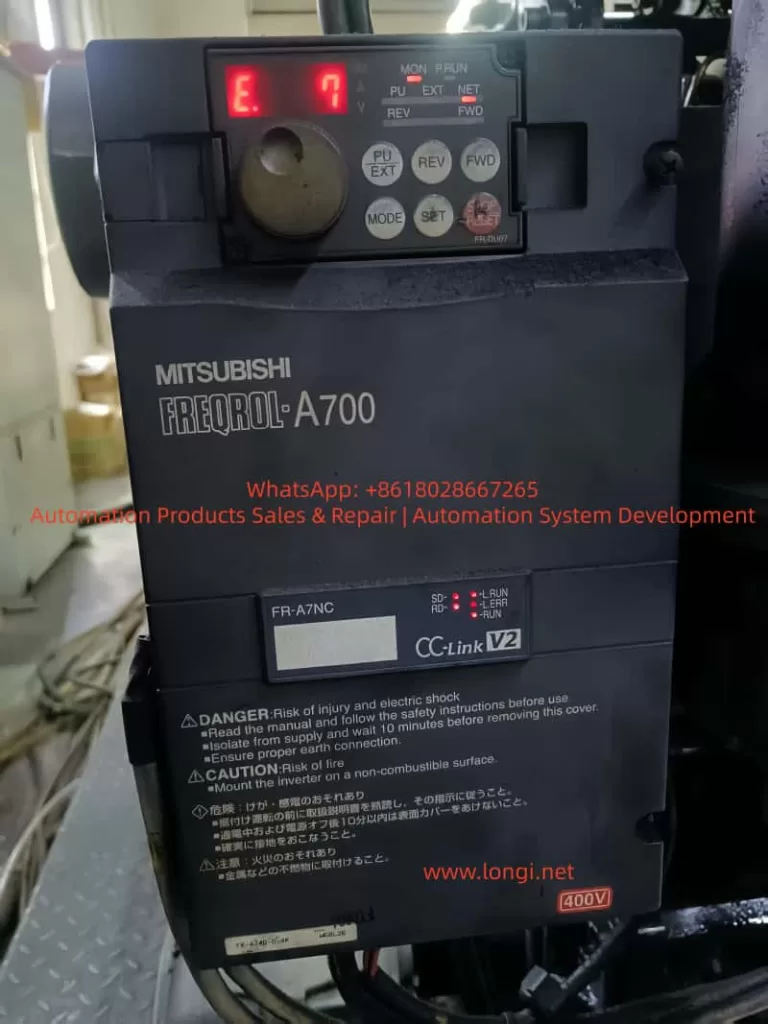
However, when the display shows “E.7” or “E.CPU”, the inverter immediately halts output, and the entire system comes to a standstill. This is often referred to by technicians as a “brain crash,” as it indicates a critical failure of the inverter’s central processing unit (CPU).

Among all protection codes, E.7 is one of the most severe. It typically signals that internal communication between control units has failed, logic processes have become unstable, or the CPU hardware itself has malfunctioned.
This article offers a comprehensive technical exploration of the E.7 (CPU Error) fault — its causes, diagnostic methods, hardware implications, repair solutions, and preventive measures — supported by real industrial case studies.


II. Understanding the Fault and System Logic

According to the FR-A700 User Manual (page 397):

E.6 / E.7 / E.CPU – CPU Error
When an internal CPU communication error occurs, the inverter stops output.
Inspection Point: Check if there are devices around the inverter that generate strong electrical noise.
Measure: If no external interference is found, contact the supplier or Mitsubishi service center.

This indicates that E.7 is a system-level protection event.
The inverter’s internal logic continuously monitors communication between the main CPU, gate driver interface, and memory/control buses. If any communication timeout or checksum failure occurs, the CPU triggers a protective shutdown to prevent unpredictable IGBT switching or hardware damage.

The main CPU fault logic in the FR-A700 involves:

  1. Abnormal communication between the main processor and gate drive circuits.
  2. Data corruption or response failure in EEPROM, ADC, or communication ICs.
  3. Watchdog timer reset caused by logic hang or power fluctuation.

When the watchdog detects that the CPU fails to respond within its monitoring period, the system declares a “CPU Communication Error” and displays E.7.


III. Technical Causes of the CPU Error

The E.7 fault generally stems from three major categories of issues:

  1. Electromagnetic interference (EMI)
  2. Power supply instability
  3. Internal control board failure

1. Electromagnetic Interference (EMI)

Industrial sites are rich in high-frequency noise sources — welding machines, large contactors, induction heaters, and switching power supplies. These generate voltage spikes and transient electromagnetic waves that couple into the control board’s circuits, disturbing the CPU clock or data bus.

Typical EMI sources include:

  • Arc welders or high-frequency induction furnaces
  • Contactors or solenoid valves switching nearby
  • Control signal lines routed in parallel with power cables
  • Improper or floating grounding systems

In such cases, E.7 may occur intermittently, often clearing after power cycling — a sign that transient interference is affecting the CPU.

Technical Recommendations:

  • Separate control wiring from power cables (minimum 10 cm apart).
  • Use twisted shielded cables for control and communication lines.
  • Ground all shields at one single point only.
  • Install proper EMI filters and ferrite cores on input lines.

2. Power Supply Fluctuations or Grounding Issues

The FR-A700 series contains multiple voltage rails — DC bus (≈540 VDC), control voltage (24 VDC), and logic voltage (5 VDC).
When any of these experience transient drops due to unstable input voltage, aging capacitors, or poor grounding, the CPU watchdog may trigger an internal reset, leading to an E.7 CPU Error.

Typical symptoms:

  • E.7 appears immediately upon power-up
  • Random alternation between E.6 and E.7
  • Display flickering or panel freezing

Diagnostic Points:

  1. Measure three-phase input balance and verify stable voltage.
  2. Check DC bus voltage ripple — excessive ripple suggests degraded capacitors.
  3. Measure 24V and 5V supply rails; ensure no drop below tolerance.
  4. Inspect the grounding system — avoid shared return paths with external PLCs or IO devices.

3. Hardware Failure on Control or Power Board

If E.7 persists after confirming stable power and minimal EMI, the most likely cause is a hardware fault.

Common hardware-related sources:

  • Damaged main CPU (e.g., Renesas or Mitsubishi custom MCU)
  • Failed EEPROM or memory IC communication
  • Broken optocouplers (HCPL-2631, etc.) between logic and driver circuits
  • Poor connection between control board and power board
  • Feedback interference caused by a shorted IGBT module

Observable signs:

  • Instant E.7 alarm at power-up
  • Unable to reset via panel or RES signal
  • FR-Configurator2 communication fails
  • No clock signal detected on the CPU oscillator

In this situation, replacing the control PCB or even the entire inverter is often the most efficient solution.


IV. Step-by-Step Diagnostic Procedure

A systematic diagnostic process can help quickly isolate the E.7 cause.

Step 1: Record and Observe

  • Note when the error occurs (during start, stop, idle, or communication).
  • Observe whether the fault happens after brief power loss.
  • Check ambient temperature (CPU overheating can cause instability).

Step 2: Insulation and Ground Testing

  • After disconnecting power and waiting at least 10 minutes, measure insulation resistance (>5 MΩ) between main terminals and ground.
  • Ensure no short between control circuits and main circuit.

Step 3: Check for Interference and Grounding Issues

  • Verify that PE grounding resistance is below 10 Ω.
  • Ensure all power cables are symmetrical (balanced three-phase).
  • Avoid “loop grounds” by ensuring star-point grounding topology.
  • For RS-485 or CC-Link communication, ground the shield at one end only.

Step 4: Monitor Power Rails

  • Use an oscilloscope to monitor 24V and 5V supplies; ensure minimal ripple (<100 mV).
  • Confirm the DC bus is steady without oscillation when idle.

Step 5: Module-Level Inspection

  • Re-seat the operation panel and connectors between boards.
  • Examine ribbon cables for oxidation or loose pins.
  • Swap with a known-good control board if available.
  • If error persists → replace power board or complete drive.

V. Repair and Replacement Strategies

1. Component-Level Control Board Repair

Qualified service technicians can:

  • Verify CPU clock oscillator output (16–20 MHz typical).
  • Check watchdog timer pulse (ICs like 74HC123).
  • Replace EEPROM, voltage regulators, or capacitors.
  • Re-solder cracked joints and clean carbon residue.
  • Add low-ESR capacitors (e.g., 47 µF × 2) near CPU power pins to enhance filtering.

2. Inverter Replacement and Parameter Recovery

When the board is irreparable:

  • Use FR-Configurator2 to back up parameters before removing the unit.
  • Install the new inverter, then restore parameters via copy function (Pr.990–Pr.999).
  • Run auto-tuning (Pr.71, Pr.80–Pr.84) to recalibrate motor characteristics.

3. Environmental Hardening

For long-term stability:

  1. Add EMI filters or isolation transformers on input side.
  2. Install surge absorbers (MOVs) between R/S/T lines.
  3. Route control and power cables separately.
  4. Maintain good cabinet ventilation and cleanliness.

VI. Case Study: CPU Error in Injection Molding Machine

An FR-A740-22K-CHT inverter was used as the main drive in a plastic injection molding machine. The unit displayed E.7 intermittently; resetting restored operation temporarily.

Investigation findings:

  • Three inverters were installed side-by-side in the same panel.
  • Control signal cables ran parallel to motor leads.
  • Ground connections were multi-pointed, creating loops.
  • Heavy dust on control board and fan filter.

Corrective actions:

  1. Re-routed control cables with shielded twisted pairs.
  2. Implemented star-point grounding.
  3. Added 100 µF capacitor to 5V rail on control board for ripple suppression.
  4. Cleaned dust and re-seated connectors.

After these measures, the machine ran for 72 hours continuously without reoccurrence.
Conclusion: E.7 was caused by EMI-induced communication loss rather than true CPU failure.


VII. Relationship Between Related Error Codes

CodeDescriptionMeaningCorrelation
E.6CPU Communication Error ACommunication loss in main logic channelOften co-occurs with E.7
E.7CPU Communication Error BInternal bus or logic timing faultMay escalate to E.CPU
E.CPUCPU Hardware FaultCPU self-check failure or watchdog timeoutSevere or persistent E.6/E.7

If E.6, E.7, and E.CPU alternate rapidly, it typically indicates either a logic power fault or crystal oscillator failure.


VIII. Preventive Engineering Practices

1. During Electrical Design

  • Provide dedicated grounding bars (no shared returns).
  • Use separate grounding cables for each inverter.
  • Add RC snubber circuits or line filters on power input.
  • Use crimp terminals for all wiring to prevent loose contacts.

2. During Installation and Commissioning

  • Test motor insulation before wiring to inverter.
  • Avoid long, unshielded communication lines.
  • Use optical isolation modules when interfacing PLCs.

3. During Routine Maintenance

  • Clean cooling channels and fans every 6 months.
  • Check fan bearings and noise levels.
  • Measure DC bus capacitor ESR annually.
  • Use heaters or dehumidifiers in damp environments.

4. Backup and Record Management

  • Regularly back up parameters via FR-Configurator2 or PU unit.
  • After replacing the control board, verify calibration parameters.
  • For aging units, perform preventive replacement of capacitors and relays.

IX. Technical Insights and Summary

The E.7 fault in the Mitsubishi FR-A700 series is a CPU communication error — a high-level protection mechanism that prevents erratic operation when the internal logic loses synchronization.
It does not relate to mechanical load or overcurrent events, but rather to the integrity of digital control.

Based on field experience, E.7 can be categorized into three scenarios:

TypeRoot CauseSolution
IntermittentElectrical noise or unstable powerImprove grounding and filtering
RecurrentLoose connectors, aged componentsMaintenance and board cleaning
PersistentDamaged CPU or control boardReplace control board or full unit

Following the logical troubleshooting flow — external causes → power check → control circuit diagnosis — enables engineers to identify the root problem quickly and avoid unnecessary replacements.

In preventive terms, a robust EMC design and proper grounding layout remain the most effective strategies to eliminate CPU communication errors in high-frequency drive systems.


X. Practical Recommendations

  • For environments with frequent E.7 errors, consider using a 1:1 isolation transformer (2 kVA or above) for the inverter’s control supply.
  • In high-temperature cabinets (>45°C), add external forced-air cooling.
  • For long-distance communication, use optical fiber isolation modules instead of RS-485 copper lines.
  • For multi-inverter systems, use independent control power supplies for each unit.

Conclusion

The E.7 CPU Error is not simply a nuisance fault — it is an intelligent self-protection feature designed to prevent catastrophic failure in the Mitsubishi FR-A700 inverter series.
Understanding its electrical, logical, and environmental causes allows engineers to perform accurate diagnostics, avoid misjudgment, and reduce downtime.

In today’s automation landscape, where system reliability and electromagnetic compatibility (EMC) are paramount, addressing E.7 is not merely about fixing an error — it’s about building resilience into every layer of the control system.

Posted on

Mitsubishi MR-J3-B Servo Amplifier “Ab” Display Fault Diagnosis and Troubleshooting Guide

Introduction

The Mitsubishi Electric MR-J3-B series servo amplifiers are precision control devices widely used in industrial automation, primarily for driving servo motors to achieve high-precision positioning, speed control, and torque control. Renowned for their high responsiveness, reliability, and ease of integration, these products are suitable for applications such as CNC machine tools, robotic arms, and printing machinery. However, during actual use, users often encounter various codes on the display, with the “Ab” display being a common initialization status indicator. According to official manuals and user feedback, “Ab” is not strictly an alarm code (Alarm) but rather a status display indicating that the servo amplifier is in the initialization phase or experiencing communication issues. Ignoring this display may result in the system failing to start normally or the motor not responding to commands, thereby affecting production efficiency.

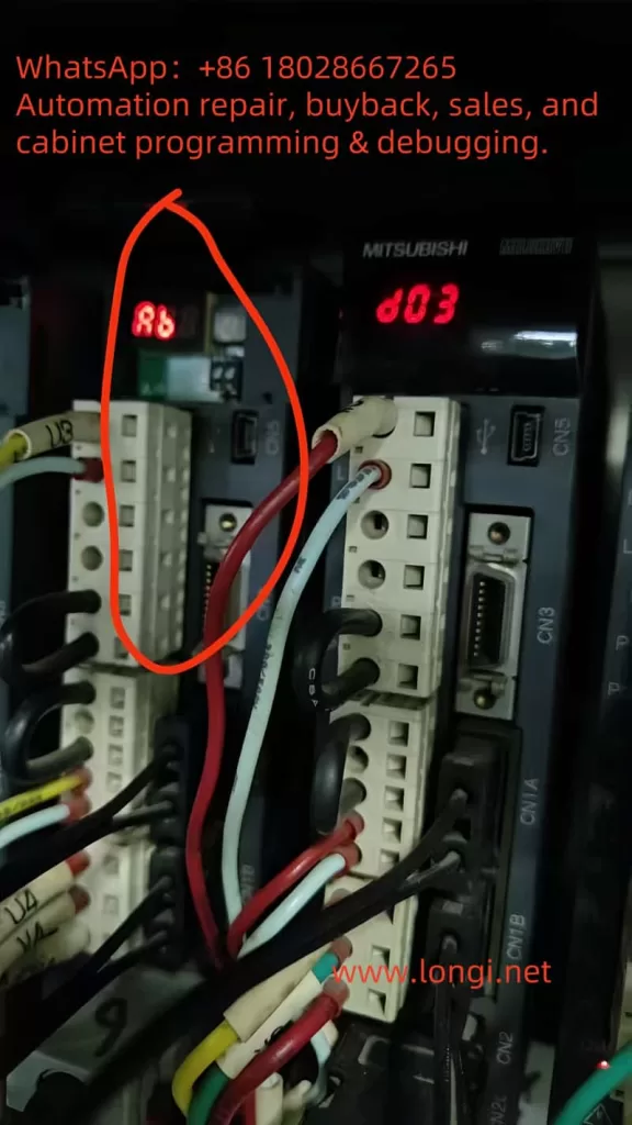
Ab MR-J3B

This guide systematically compiles knowledge about the “Ab” display based on Mitsubishi’s official manuals (e.g., MR-J3-B SERVO AMPLIFIER INSTRUCTION MANUAL SH030051G), troubleshooting guides, and user experiences from online forums. The content covers explanations of its meaning, cause analysis, diagnostic methods, solution steps, preventive measures, and practical cases, aiming to provide comprehensive reference for engineers and technicians. Understanding the “Ab” display hinges on its close relationship with the SSCNET III communication protocol, axis number settings, and power sequencing. Through this guide, you will learn how to quickly locate problems and restore system operation. The following content is logically structured to ensure each step is supported by evidence.

Meaning of “Ab” Display and Initialization Process

On the 5-digit 7-segment LED display of the MR-J3-B servo amplifier, “Ab” is a specific initialization status code, not a typical alarm (e.g., “AL.10” indicates undervoltage). According to the official manual (SH030051G, pages 4-6), when the servo amplifier is powered on, if the servo system controller (e.g., PLC or motion controller) is not turned on, the axis number settings do not match, or there is a communication fault, the display will show “Ab”. This indicates that the system is attempting to initialize communication parameters but has failed to complete synchronization.

The initialization process is a multi-stage sequence that typically includes the following display codes:

  • Ab: Initialization communication phase. The servo amplifier detects that the controller is not responding or the axis numbers are inconsistent. At this point, the system is in the “Ready off” state and cannot enter servo readiness mode.
  • AC: Synchronization completion phase. If “Ab” quickly switches to “AC”, it indicates that preliminary communication has been established.
  • Ad: Parameter communication phase. The servo amplifier reads parameter settings from the controller.
  • AE: Encoder communication phase. Verifies the servo motor encoder signal.
  • AF: I/O signal communication phase. Checks external input/output signals.
  • AH: Initialization complete. The system enters normal status, displaying codes such as “b01” (readiness off) or “d01” (servo on).
  • AA: If the controller is completely turned off, “AA” is displayed, indicating waiting for SSCNET communication to resume.

If the display cycles through “Ab → AC → Ad → Ab”, it indicates a persistent communication error or a fault in the servo system controller (manual, pages 4-6). The manual also mentions that in the revised version of the manual (e.g., July 2007), “Ab.” was corrected to “Ab” to avoid user confusion (Appendix App.-9). Additionally, in the safety version of the manual, “Ab” is closely related to the integrity of the SSCNET III fiber-optic cable. If the cable is disconnected or contaminated, it interrupts optical module operation, causing the rear axis to display “AA” and activating dynamic braking (Section 3-2).

It is important to emphasize that “Ab” is not a fault alarm and therefore does not trigger automatic shutdown or historical records (e.g., parameter PA09 is used to clear alarm history, page 5-24). However, if ignored, it may evolve into actual alarms such as “34” (continuous receive error) or “36” (intermittent receive error), which are related to SSCNET cable issues (pages 8-5 to 8-6). Understanding this process helps distinguish “Ab” from similar displays, such as “rb” (possibly a misreading) or “E6” (overload warning).

Possible Causes of “Ab” Display

The root cause of the “Ab” display usually lies in communication initialization failure, which can be categorized into three main types: power sequencing issues, mismatched settings, and hardware faults. The following provides a detailed analysis based on the manual and user feedback.

  1. Improper Power Sequencing: When the servo amplifier is powered on, if the servo system controller is not turned on first, the amplifier cannot receive control signals, causing initialization to get stuck at the “Ab” stage (manual, page 4-8). In multi-axis systems, if the power to the front-axis amplifier is interrupted, the rear axis will display “AA” and force a stop (Section 3-2). Forum user feedback indicates that this situation is common after system restarts or maintenance, especially when multiple amplifiers share the same power supply.
  2. Mismatched Axis Number Settings: The MR-J3-B uses a rotary axis setting switch (SW1) to define axis numbers, ranging from 0 to F (corresponding to axes 1 to 16). If the axis number set by SW1 does not match the axis number assigned by the servo system controller (e.g., QD75MH positioning module), the system cannot synchronize and displays “Ab” (pages 1-11 and 3-61). The manual warns that in multi-axis SSCNET networks, duplicate axis numbers can cause the entire system to fail (page 3-61). Additionally, in interpolation mode (e.g., X-Y table control), mismatched axis numbers can also affect position loop gain (PB07 parameter, page 6-4).
  3. SSCNET III Communication Hardware Faults: SSCNET III is a fiber-optic communication protocol that is high-speed (150 Mbps) but sensitive to cables. Common issues include:
    • Disconnected, dirty, damaged, or excessively bent cables, leading to degraded optical characteristics (alarms 34/36, page 8-5).
    • Noise interference: Electromagnetic noise from nearby power lines or motor cables can intermittently interrupt communication (page 8-6).
    • Optical module faults: When the control circuit power is turned off, the optical module does not operate, causing communication interruptions (Section 3-2).
    • USB communication-related issues: If using MR Configurator software for diagnosis, a damaged cable may trigger alarms “8A” or “8E” (Chapter 8).

Other minor causes include loss of absolute position (alarm 25, low battery voltage or origin not set, page 8-3) and parameter errors (alarm 37, page 8-7), which may indirectly cause initialization failures. Forum discussions (e.g., MrPLC.com) report that “Ab” is often associated with loose encoder cables or CPU grounding issues, but the official manual emphasizes the SSCNET level more.

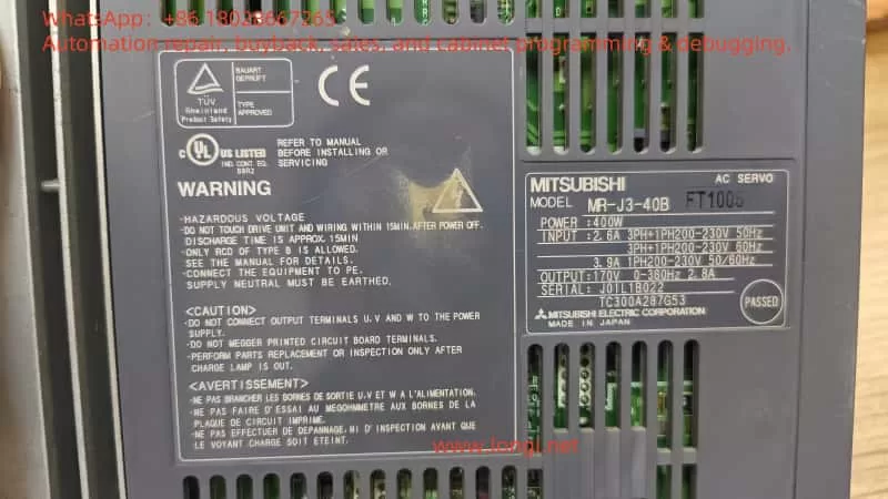
MR-J3-40B

Diagnostic Steps: How to Confirm and Locate the Problem

Diagnosing the “Ab” display requires a systematic approach, combining display observations, software tools, and hardware checks. The following are recommended steps based on Chapter 4 (Startup) and Chapter 8 (Troubleshooting) of the manual:

  1. Observe Display Changes: Record the display sequence after power-on. If it remains fixed at “Ab”, check the controller power supply; if it cycles through “Ab-AC-Ad-Ab”, suspect axis number or communication faults (page 4-6). Use the display navigation buttons to switch to status mode and view motor speed, command pulse frequency, and load rate (page 13-50).
  2. Check Power Supply and Sequencing: Ensure that the servo system controller is powered on first, followed by the amplifier. Verify the input voltage (200-230 V AC, confirmed by the label). Wait 15 minutes for discharge before re-powering (safety precautions, page A-1).
  3. Verify Axis Number Settings: Use the SW1 switch to check the axis number and ensure it matches the controller (page 1-11). In multi-axis systems, verify the SW1 settings for each amplifier individually to avoid duplicates.
  4. SSCNET Cable Diagnosis: Visually inspect the fiber-optic cable for damage, dirt, or excessive bending (minimum bending radius 50 mm, page 3-33). Clean the connector end faces and use noise suppression measures such as ferrite cores (page 8-5). If intermittent errors are suspected, monitor communication at 70 ms intervals (alarm 36).
  5. Software Diagnosis: Connect USB to the CN5 port and use MR Configurator software to read error logs and parameters (page 4-10). The software can simulate JOG operation and positioning tests to confirm encoder signals (page 4-13, set PC05=1 in motorless operation mode).
  6. Environmental and Hardware Checks: Confirm that the ambient temperature (0-55°C), humidity (<90% RH), and vibration (<49 m/s², page A-3) are within specifications. Check grounding, terminal tightness, and regenerative resistor connections (MR-RB series, pages 188-190).

If the diagnosis still shows “Ab”, record the alarm history (parameter PC21, page 13-56) and consult Mitsubishi technical support.

Solutions: Step-by-Step System Restoration

Once the cause is located, resolving the “Ab” display is relatively straightforward. The following are targeted solutions:

  1. Adjust Power Sequencing: Turn on the controller power supply first and wait for stabilization before powering on the amplifier. The manual recommends using the DO forced output function to verify I/O signals (page 4-2).
  2. Correct Axis Numbers: Adjust SW1 to the correct axis number and restart the system. Ensure that axis numbers are unique in multi-axis networks (page 3-61). If interpolation is involved, manually set the PB07 gain to the minimum value (page 6-4).
  3. Repair SSCNET Communication:
    • Replace or clean cables: Disconnect the power supply and replace damaged cables (page 3-33).
    • Noise suppression: Add ferrite filters or isolate noise sources (page 8-6).
    • For alarms 34/36, mark the servo as off, disconnect the power supply, use MR Configurator to identify the cause, and ensure safety before resetting (Chapter 8).
  4. Absolute Position-Related Issues: If accompanied by alarm 25, replace the battery (MR-J3BAT), set the origin, and power cycle (page 8-3).
  5. Test Operation: Perform JOG (speed test) or positioning operations in MR Configurator to confirm motor response (page 4-10). Enable forced stop 2 (EM2) to prevent accidents (page 4-4).
  6. Advanced Reset: Clear the alarm history (PA09=1, restart, page 13-56). If the fault persists, consider replacing the amplifier or controller.

User feedback indicates that these steps can resolve over 90% of “Ab” problems, especially the power sequencing adjustments often mentioned in forums, which provide immediate results.

Preventive Measures: Avoiding Recurrence of “Ab” Display

Prevention is better than cure. The following measures are based on the safety and maintenance sections of the manual (pages A-1 to A-3 and Section 2-5):

  1. Standardize Operating Procedures: Develop a power-on sequencing manual to ensure that the controller is turned on first. Provide regular training for operators.
  2. Regular Maintenance: Inspect SSCNET cables, SW1 settings, and environmental conditions quarterly. Monitor battery voltage (>3.0 V) and replace it every 3 years (page 8-3).
  3. Hardware Optimization: Use the recommended cable length (<50 m) and avoid routing near noise sources. Install regenerative resistors (MR-RB) to prevent overloads (page 188).
  4. Software Monitoring: Integrate MR Configurator into daily inspections to view parameters and logs in real time. Set parameter alarm thresholds (e.g., overload warning E1, page 8-10).
  5. Backup and Updates: Back up parameter settings and regularly update manual revisions (e.g., the July 2007 version corrected the display, page App.-9).

These measures can significantly reduce the incidence of “Ab” and improve system reliability.

Practical Case Analysis

Case 1: In a forum discussion, a user reported that an MR-J2S (similar to J3) displayed “AB” due to the controller power being turned off. Solution: Turn on the controller first and restart the amplifier, and the display returned to “d01”.
Case 2: Another user had multiple faulty units displaying “Ab”, diagnosed as duplicate axis numbers. Adjusting SW1 resolved the issue and prevented system瘫痪 (system shutdown).
Case 3: A video titled “Mitsubishi Quick Tips” demonstrated the “Ab” display along with “b01”, “E6”, etc., emphasizing communication checks. User comments confirmed that cable cleaning was effective.
Case 4: In a troubleshooting PDF, communication errors caused the “Ab” display to cycle, and replacing the SSCNET cable restored normal operation.

These cases prove that rapid diagnosis can save downtime.

Conclusion

The “Ab” display is a common indicator during the initialization process of the MR-J3-B servo amplifier, primarily caused by power sequencing, axis number settings, or SSCNET communication issues. Through the systematic analysis in this guide, you can comprehensively understand its meaning and practical troubleshooting methods, from diagnosis to resolution. It is recommended to always refer to the official manual and use MR Configurator tools for diagnosis. If the problem is complex, contact Mitsubishi support promptly. Proper maintenance can not only resolve “Ab” issues but also enhance overall system performance, ensuring efficient industrial production.

Posted on

Mitsubishi E700 (E740) Inverter E.AIE Fault Code: Analog Input Error Analysis and Solutions

1. Introduction

The Mitsubishi E700 series inverters, including the E740 model, are widely used high-performance devices in industrial automation, renowned for their efficiency, stability, and flexibility. However, during operation, these inverters may encounter faults, with the “E.AIE” fault code (Analog Input Error) being a common issue. This article provides an in-depth analysis of the E.AIE fault’s meaning, potential causes, and systematic troubleshooting steps and solutions to help users quickly identify and resolve the issue. Additionally, preventive measures are discussed to minimize the occurrence of similar faults.

FR-E740

2. Meaning of the E.AIE Fault Code

According to the Mitsubishi E700 Inverter Manual (hereinafter referred to as the manual), the E.AIE fault code indicates an abnormality in the analog input. This fault is typically related to the analog input signals (e.g., 0-10V voltage or 4-20mA current) received through terminals (such as terminals 2 or 4), which are used to set motor operating frequency or other control parameters. When the inverter detects that these signals are out of range, missing, or unstable, it triggers the E.AIE protection function, halting output and displaying the fault code on the operation panel.

Possible Triggering Conditions

  1. Signal Out of Range: Input signal exceeds the inverter’s supported range (e.g., voltage > 10V or current > 20mA).
  2. Signal Transmission Issues: Wiring problems or electromagnetic interference causing signal interruption or distortion.
  3. External Device Failure: Malfunction of devices providing the signal (e.g., potentiometers, sensors, or PLCs).
  4. Parameter Setting Errors: Incorrect settings for parameters related to analog input, such as PR.73 and PR.267.
  5. Internal Inverter Issues: Damage to the analog input circuit.

Understanding the meaning of E.AIE allows for a multi-angle analysis of its causes and the development of troubleshooting strategies.

3. Possible Causes of the E.AIE Fault

The E.AIE fault may stem from external factors or issues within the device itself. The following is a detailed breakdown of potential causes:

3.1 Abnormal Analog Input Signal

The analog input signal is typically provided by an external device to control frequency or parameters. The manual (PAGE 71) notes that the E700 series supports 0-5V, 0-10V voltage inputs, and 4-20mA current inputs. If the signal exceeds these ranges, the inverter triggers protection.

  • Possible Issues:
    • Abnormal output from an external device (e.g., voltage exceeding 10V).
    • Unstable or missing signal.
  • Example: A damaged potentiometer causing voltage fluctuations, or a PLC output module failing, resulting in current exceeding 20mA.

3.2 Wiring Issues

Wiring problems are a common cause of analog input abnormalities. The manual (PAGE 19 and PAGE 23) provides detailed wiring requirements for control circuit terminals.

  • Possible Issues:
    • Loose or Disconnected Wiring: Poor contact at terminals 2 (voltage input), 4 (current/voltage input), or 5 (common terminal).
    • Wiring Errors: Voltage signal mistakenly connected to a current terminal, or the common terminal not properly connected.
    • Electromagnetic Interference: Unshielded signal lines or proximity to power lines causing signal distortion.
  • Example: Signal lines not using shielded cables, affected by electromagnetic interference from nearby motor operation.

3.3 External Device or Sensor Failure

Analog signals are often sourced from external devices such as potentiometers, sensors, or PLCs. If these devices fail, it can lead to signal abnormalities.

  • Possible Issues:
    • Aged potentiometer causing unstable voltage output.
    • Damaged sensor interrupting the 4-20mA current signal.
    • Abnormal power supply to external devices affecting signal output.
  • Example: A 4-20mA pressure sensor outputting abnormal current due to an internal short circuit.

3.4 Parameter Setting Errors

Inverter parameter settings directly affect analog input recognition. The manual (PAGE 49 and PAGE 71) highlights key parameters:

  • PR.73 (Analog Input Selection): Defines the input type for terminal 2 (e.g., 0-10V or 4-20mA).
  • PR.267 (Terminal 4 Input Selection): Defines the input type for terminal 4, supporting 0-5V, 0-10V, or 4-20mA.
  • PR.125/PR.126 (Frequency Setting Gain): Calibrates the relationship between analog signals and frequency.
  • Possible Issues: Mismatched settings for PR.73 or PR.267 with the actual signal type, preventing correct signal recognition.
  • Example: PR.267 set to “0” (4-20mA) while the actual input is a 0-10V signal, leading to a read error.

3.5 Internal Inverter Circuit Failure

If external signals and wiring are normal but the fault persists, it may indicate a hardware issue.

  • Possible Issues:
    • Damage to the analog input circuit (e.g., A/D conversion module).
    • Aging or moisture-related degradation of internal circuits.
  • Example: Long-term operation in a humid environment causing circuit board corrosion.
E.AI E

4. Role of PR.267 in the E.AIE Fault

PR.267 is a critical parameter related to analog input, specifically used to set the input type for terminal 4. According to the manual (PAGE 71), PR.267 options include:

  • 0: 4-20mA current input.
  • 1: 0-5V voltage input.
  • 2: 0-10V voltage input.

The purpose of PR.267 is to inform the inverter how to interpret the analog signal received via terminal 4. For instance, if PR.267 is set to “0,” the inverter expects a 4-20mA current signal; if set to “2,” it expects a 0-10V voltage signal.

Relationship Between PR.267 and E.AIE Fault

When the PR.267 setting does not match the actual input signal type, the inverter may fail to recognize or process the signal correctly, triggering an E.AIE fault.

  • Mismatch Example: If PR.267 is set to “0” (current input) but the input is a voltage signal, the inverter misinterprets the data, leading to an E.AIE error.
  • Signal Out of Expected Range: Even with the correct signal type, if the PR.267 setting causes the inverter to expect a range that differs from the actual input (e.g., voltage input but exceeding 10V), a fault may occur.

Thus, checking the PR.267 setting is essential during E.AIE fault troubleshooting.

5. Steps to Resolve the E.AIE Fault

Based on the above causes, the following are systematic troubleshooting and resolution steps:

5.1 Check the Analog Input Signal

  • Action:
    • Use a multimeter to measure the signal between terminals 2 (voltage input) or 4 (current/voltage input) and terminal 5.
    • Verify the signal is within the normal range (0-5V, 0-10V, or 4-20mA).
  • Solution:
    • If the signal exceeds the range, adjust the external device output.
    • If the signal is missing, check the external device’s operation.

5.2 Inspect Wiring and Shielding

  • Action:
    • Check the integrity of terminals 2, 4, and 5 wiring, referring to the manual (PAGE 15) for the wiring diagram.
    • Ensure signal lines use shielded cables with the shield grounded (PAGE 33).
  • Solution:
    • Tighten loose terminals or replace damaged wiring.
    • Install shielded cables and keep them away from power lines to reduce interference.

5.3 Test External Devices

  • Action:
    • Disconnect the external device and use a signal generator to input a standard signal, observing if the fault disappears.
  • Solution:
    • If the fault resolves with a direct input, inspect and replace the faulty external device.

5.4 Check Parameter Settings (Focus on PR.267)

  • Action:
    • Enter parameter mode to verify PR.73 (terminal 2) and PR.267 (terminal 4) match the input signal types.
    • Specific steps:
      • Check the current value of PR.267.
      • Confirm the actual signal type at terminal 4 (voltage or current).
      • Adjust PR.267 to the matching value (e.g., “2” for 0-10V).
    • Verify PR.125 and PR.126 are correctly calibrated (PAGE 70).
  • Solution:
    • Adjust PR.73 and PR.267 to the correct values.
    • If unsure, reset parameters to factory settings (PAGE 42) and reconfigure.

5.5 Inspect Inverter Hardware

  • Action:
    • Check terminals for signs of burning or damage.
    • If possible, replace the control board for testing.
  • Solution:
    • If hardware failure is confirmed, contact Mitsubishi service or a professional technician (PAGE 113).

5.6 Reset and Test

  • Action:
    • Press the “STOP/RESET” key to reset the fault (PAGE 95).
    • Restart the inverter and conduct a trial run.
  • Solution:
    • If the fault persists, repeat the steps or seek technical support.

6. Preventive Measures

To reduce the occurrence of E.AIE faults, consider the following measures:

  1. Regular Wiring Checks: Inspect terminal integrity and signal line condition monthly.
  2. Use Quality Equipment: Select external devices compatible with the inverter.
  3. Optimize Installation Environment: Follow manual guidelines (PAGE 14) to avoid harsh conditions.
  4. Parameter Backup and Verification: Back up parameters after initial setup and periodically check PR.267 and other key settings.
  5. Regular Maintenance: Clean the inverter annually and inspect internal circuits as recommended (PAGE 113).

7. Case Study

Consider a FR-E740-7.5K-CHT inverter displaying an E.AIE fault:

  • Troubleshooting: Measurement shows a 0-10V voltage input at terminal 4, but PR.267 is set to “0” (4-20mA).
  • Root Cause: PR.267 mismatch with the actual signal type.
  • Solution: Adjust PR.267 to “2” (0-10V), reset the inverter, and the fault is cleared.
  • Prevention: Record PR.267 settings and regularly inspect external devices.

8. Conclusion

The E.AIE fault in Mitsubishi E700 (E740) inverters is typically caused by abnormal analog input signals, wiring issues, external device failures, parameter setting errors (especially PR.267), or internal hardware damage. By inspecting signals, wiring, devices, parameters, and hardware, users can effectively resolve the issue. Notably, correctly setting PR.267 is crucial to avoiding E.AIE faults. Preventive measures, such as regular parameter checks and backups, enhance equipment reliability. If troubleshooting proves challenging, contacting Mitsubishi technical support is recommended to ensure production efficiency and equipment safety.

    Posted on

    Implementation Plan for Automated Control System of Mooncake Production Line

    Based on Longi 900 Series Inverter and Mitsubishi FX3U PLC

    1. Project Background

    Mooncakes are a traditional Chinese delicacy with cultural significance, especially during the Mid-Autumn Festival. With increasing market demand for quality, production capacity, and hygiene standards, traditional manual production methods have become inadequate. Therefore, building an efficient, stable, and intelligent automated mooncake production system is crucial.

    This project proposes an automation control system integrating the Mitsubishi FX3U PLC, Weintek HMI, and Rongji 900 series inverter to manage the entire mooncake manufacturing process—from dough and filling feeding, encrusting, pressing, forming, tray loading, baking, cooling, to final packaging. The system aims to provide a flexible, reliable, and cost-effective solution for small to medium-sized food manufacturers.


    Schematic Diagram of Mooncake Production Line

    2. Detailed Workflow and Production Line Principle

    2.1 Overall Operating Principle

    The mooncake production line consists of a series of interconnected machines controlled by PLC logic, frequency inverters, and HMI interfaces. Key mechanisms include:

    • Synchronization of multiple machines via conveyor belts;
    • Detection of workpiece positions using photoelectric sensors;
    • Speed control of motors via inverters for precise encrusting, molding, and tray feeding;
    • Time-sequenced logic from the PLC ensures no process conflicts;
    • Real-time monitoring and parameter setting via HMI.

    2.2 Detailed Workflow Breakdown

    StageDescription
    1. Raw Material FeedingDough and filling are independently fed via hoppers. Dough is delivered using screw or belt feeders, while filling (e.g., lotus paste, egg yolk) is fed by twin-screw or extrusion pumps.
    2. EncrustingAn automatic encrusting machine proportionally wraps dough around the filling. Three synchronized feeding systems ensure consistent weight and shape of each mooncake ball.
    3. Molding and PressingMooncake balls are first shaped by a vibrating pre-former, then enter the press system. The top-down mold structure creates floral patterns and sets thickness using pneumatic or servo mechanisms.
    4. Conveying & AlignmentMolded mooncakes are neatly aligned by guide rails and pushed into baking trays using mechanical pushers. The process is synchronized to avoid overlaps or gaps.
    5. BakingMulti-zone tunnel ovens provide accurate heat distribution (e.g., upper/lower heat). Temperature sensors and alarms ensure safe operation. Advanced models may include vision-based feedback control.
    6. CoolingAfter baking, mooncakes cool for 5–10 minutes via mesh-belt forced-air systems. Adjustable air speed/direction ensures even cooling, with flipping mechanisms for underside exposure.
    7. InspectionMetal detectors and weight checkers remove defective or foreign-object-containing products.
    8. PackagingQualified mooncakes are guided by robotic arms or channels into packaging machines for automatic wrapping, sealing, coding, and boxing. The system synchronizes with the conveyor line via PLC signals.

    This line typically supports 50,000 to 200,000 pieces/day with a throughput of 60–120 pieces per minute and easily accommodates various flavors and sizes.


    Automatic Mooncake Production Line

    3. System Architecture

    3.1 Mitsubishi FX3U PLC

    • Manages all I/O signals (e.g., sensors, buttons, alarms);
    • Includes main program, interrupt routines, and PID modules for real-time operation;
    • MODBUS-compatible for seamless communication with Rongji inverters;
    • Expandable with high-speed counting modules for precise positioning.

    3.2 Rongji 900 Series Inverter

    • Drives dough feeders, encrusters, mold presses, tray pushers, etc.;
    • Supports VF and SVC modes for high torque at low speeds;
    • Built-in PID for closed-loop control (e.g., pressure in mold presses);
    • Multi-speed (F4) support with 8-step preset frequencies;
    • Rich I/O terminals for flexible integration.

    3.3 Weintek HMI (e.g., TK6071iQ)

    • Communicates with PLC via RS-232 or MODBUS-RTU;
    • Enables menu control, recipe switching, alarms, and statistics;
    • Supports USB recipe import/export and data logging for quality control.

    Mooncake Production Control System

    4. Sample Control Logic

    Encrusting Module

    • DI1: Start signal
    • AI1: Speed reference (from HMI or upper system)
    • DO1: Completion signal to trigger the next stage

    Molding Module

    • PLC monitors position sensor and triggers press motor;
    • Rongji 900 inverter reads pressure sensor input via AI and uses PID to maintain consistent pressing force.

    Tray Loading Module

    • PLC controls solenoid valves and pushers based on production rhythm;
    • Light sensors detect tray availability;
    • System halts and alarms when trays are missing.

    5. Advantages of Longi 900 Series Inverter

    The longi 900G3 inverters demonstrated the following key strengths in this project:

    • Strong Low-Speed Torque: 150% torque at 0.5Hz ensures stable encrusting and precise tray loading;
    • Flexible Control Modes: VF and SVC switching adapts to fast feeding and slow pressing tasks;
    • Built-in PID: Reduces PLC workload and hardware requirements;
    • Compact and Cost-Effective: Ideal for upgrading production lines in small/medium food factories;
    • Simple, Reliable Communication: Easy-to-configure MODBUS registers speed up commissioning.

    6. Conclusion

    This automation system combines Mitsubishi FX3U PLC, Rongji 900 inverters, and Weintek HMI to create a comprehensive, efficient, and stable mooncake production solution. It features flexible parameter settings, smooth operation, high productivity, and easy scalability and maintenance.

    As a key drive component, the Longi inverter stands out for its excellent performance and affordability—making it not only ideal for this project, but also highly recommended for other food processing lines such as pastry, frozen food, and beverage packaging.


    Posted on

    LTI Motion ServoC Servo Drive Application Solution for Ceramic Rolling Forming Equipment (Based on Mitsubishi FX-3U Series PLC)

    1. Overview
    Ceramic rolling forming equipment is a typical multi-axis automatic machine widely used in the initial pressing of electronic, structural, and functional ceramics. The system usually consists of a servo control unit, electrical control system, pneumatic components, and a rolling head. This document introduces in detail how to apply the LTI Motion ServoC series servo drive in combination with the Mitsubishi FX3U series PLC, covering the application strategy, wiring diagram, parameter configuration, and control logic.

    ServoCplus

    2. Application Scenario and System Structure
    This system involves two servo control units:

    • Pressing Axis Servo: Drives the pressing roller vertically to compress ceramic blanks.
    • Rotary Table Servo: Controls intermittent indexing of the rotary table for sequential forming.

    3. Key Functional Requirements

    • Precise positioning of the pressing head for consistent product thickness.
    • Indexing rotation of the rotary table with accurate angular control.
    • Multi-sensor interlock with limit switches and origin sensors.
    • Safety integration with emergency stops, alarms, and feedback loops.

    4. Hardware and Wiring Configuration

    • PLC: Mitsubishi FX3U-48MR/ES-A
    • Servo Drive: ServoC SGS4.0750.0012.0000.0 (LTI Motion)
    • Motor: Matching LTI servo motor (1.5~2.2kW)
    • Power Supply: 3-phase 400VAC

    5. Detailed Servo Wiring
    5.1 Pressing Servo (I/O Mode Control)

    ServoC TerminalFunctionConnect to PLC
    ISD00STR (Forward)Y2
    ISD01STL (Reverse)Y3
    ENPOEnableY4
    DGNDGround0V

    5.2 Rotary Table Servo (Pulse + Direction Mode)

    ServoC TerminalFunctionConnect to PLC
    ME_A+Pulse+Y0
    ME_B+Direction+Y1
    ENPOEnableY4

    5.3 Sensor Inputs

    SensorDescriptionConnect to PLC
    Origin SensorPressing Axis HomeX3
    Bottom SensorPressed PositionX4
    Table SensorIndex CompleteX5
    LTI MOTION SC54

    6. ServoC Parameter Configuration

    • P145 = 4: Position control mode
    • P152 = 1 or 2: Set input mode to pulse+direction or I/O trigger
    • P210 = 2; P211 = 3: Set ISD00 to STR, ISD01 to STL
    • P483 = 2 or 3: Motor direction configuration
    • P759 / P760: Software limit for press upper/lower bounds
    • P803: Position error tolerance

    7. Control Logic Sequence

    1. Power ON → Y4 output to enable servos.
    2. Origin detection via X3 → Set M10 (homed flag).
    3. Start pressing:
      • X0 input triggers Y2 = ON (STR), Y3 = OFF (STL).
      • X4 bottom sensor triggers M20.
    4. Return press head:
      • X1 input triggers Y3 = ON (STL), Y2 = OFF.
    5. Rotate table:
      • X2 input + M20 triggers 2000 pulses via Y0 and DIR = Y1.
      • X5 confirms rotation complete (M31).

    8. Ladder Diagram (Simplified)

    LD M8013
    OUT Y4 ; Servo Enable
    
    LD X3
    OUT M10 ; Homed flag
    
    LD X0 AND M10
    OUT Y2
    RST Y3
    
    LD X1 AND M10
    OUT Y3
    RST Y2
    
    LD X4
    OUT M20
    
    LD X2 AND M20
    RST M20
    SET Y1
    PLS Y0 K2000
    
    LD X5
    OUT M31
    RST M30
    

    9. Diagrams and Application Notes

      ServoC_FX_ConnectionDiagram

      10. Conclusion and Recommendations
      This solution demonstrates the application of ServoC servo drives in high-precision ceramic roller forming machines using Mitsubishi FX3U PLCs.

      Best Practices:

      • Set software travel limits.
      • Implement emergency stops and feedback alarms.
      • Always home the servo before operation.
      • Use opto-isolated I/O to reduce interference.

      Future Extensions:

      • Integrate HMI for parameter recipes and alarms.
      • Add pressure sensors and linear encoders for quality control.
      • Expand to multi-station synchronization with communication protocols.
      Posted on

      Mitsubishi FR-A700 Inverter E.ou2 Fault: Analysis and Solutions for Overvoltage During Constant Speed Operation

      Abstract

      This article provides a detailed analysis of the E.ou2 fault (overvoltage during constant speed operation) in the Mitsubishi FR-A700 series inverter. By integrating manual content with real-world application scenarios, it explores the causes, troubleshooting steps, and solutions to help users quickly diagnose and resolve the issue, ensuring stable equipment operation.

      Keywords

      Mitsubishi FR-A700, E.ou2 fault, overvoltage during constant speed, inverter, regenerative energy

      1. Introduction

      The Mitsubishi FR-A700 series inverters are widely recognized for their excellent performance in industrial motor control, particularly in applications like injection molding machines. However, during operation, inverters may trigger fault codes such as the user-reported “E.ou2.” According to the manual and the screenshot provided by the user, E.ou2 indicates an “overvoltage during constant speed operation,” meaning the main circuit DC voltage exceeds a safe threshold during fixed-speed operation, activating the protection mechanism. This article delves into this fault and offers practical solutions.

      E.OU2

      2. Definition and Causes of the E.ou2 Fault

      The E.ou2 fault is a protective error code in the Mitsubishi FR-A700 inverter, specifically denoting “overvoltage during constant speed operation.” When the inverter detects that the main circuit DC voltage surpasses the specified limit (typically related to the power supply voltage and device configuration, e.g., a threshold in a 400V system), it automatically stops output to safeguard the equipment. The primary causes of this fault include:

      • Excessive Regenerative Energy: During constant speed operation, the motor may generate significant regenerative energy due to load characteristics or mechanical inertia, feeding back into the inverter’s DC bus and raising the voltage.
      • Improper Parameter Configuration: For instance, if Pr.22 (stall prevention operation level) is set too low, it may fail to effectively suppress voltage fluctuations.
      • Abnormal Power or Load: Unstable power supply voltage or sudden load changes (e.g., process adjustments in an injection molding machine) may exacerbate regenerative energy production.

      3. Fault Manifestations and Real-World Case

      Based on the user-provided image, the inverter display clearly shows the “E.ou2” error code with the “RUN” light off, indicating that the device has stopped. This issue may occur in the following scenarios:

      • Time Pattern: The user noted that the equipment runs normally in the morning but frequently faults at noon, possibly due to rising environmental temperatures or changes in production load.
      • Industrial Environment: The image reveals dust accumulation on the inverter’s surface, suggesting prolonged operation in a harsh environment, which may impair heat dissipation and worsen the fault.

      4. Troubleshooting and Solutions

      To effectively address the E.ou2 fault, users are advised to follow these step-by-step troubleshooting and improvement measures:

      4.1 Parameter Check and Adjustment
      • Pr.22 (Stall Prevention Operation Level): Verify that this parameter is not lower than the motor’s no-load current. If it is, adjust it to a value higher than the no-load current to prevent erroneous protection triggers.
      • Pr.882 ~ Pr.886 (Regenerative Feedback Function): Enable and optimize these parameters to manage regenerative energy effectively. Refer to page 365 of the manual for specific settings.
      4.2 External Equipment Optimization
      • Braking Unit: If regenerative energy is significant, installing a braking unit to dissipate excess energy through resistors is recommended.
      • Common DC Bus Converter (FR-CV): For frequent overvoltage issues, using an FR-CV can efficiently absorb regenerative energy.
      • Power Supply Inspection: Use a multimeter or oscilloscope to check the input power stability, ensuring voltage fluctuations stay within the inverter’s allowable range.
      4.3 Environmental Improvements
      • Heat Dissipation Management: Ensure proper ventilation for the inverter, adding fans or air conditioning, especially during high-temperature periods (e.g., noon).
      • Cleaning Maintenance: Regularly remove dust from the inverter’s surface to prevent poor heat dissipation from causing cascading issues.
      4.4 Data Logging and Analysis
      • Operation Log: Record data such as load, speed, and environmental temperature at the time of the fault to identify potential patterns.
      • Fault History: Use the inverter’s MON mode to review historical fault records for diagnostic support.
      FR-A700

      5. Case Analysis and Recommendations

      Based on the user’s feedback and image data, the frequent occurrence of the E.ou2 fault at noon may be linked to the following factors:

      • Temperature Impact: Rising environmental temperatures at noon reduce heat dissipation efficiency, making DC bus voltage more likely to exceed limits.
      • Load Fluctuations: Production process adjustments may lighten the load, increasing regenerative energy.
        For this scenario, the following recommendations are suggested:
      1. Enhance heat dissipation measures during high-temperature periods, such as temporarily adding fans.
      2. Investigate load characteristics during noon hours and adjust operating parameters or processes as needed.
      3. Implement regular maintenance to ensure long-term equipment stability.

      6. Conclusion

      The E.ou2 fault is a common overvoltage issue in Mitsubishi FR-A700 inverters during constant speed operation. By optimizing parameter settings, installing external equipment, improving heat dissipation, and conducting regular maintenance, users can significantly reduce fault occurrence and enhance equipment reliability. The troubleshooting steps and solutions provided in this article are universally applicable to similar scenarios.

      7. References

      • Mitsubishi FR-A700 Series Inverter User Manual

      Posted on

      User Guide for Mitsubishi FR-A500 (A540 and A520) Series Inverter


      The Mitsubishi FR-A500 series inverter, including models A540 and A520, is a widely used device in the field of industrial control. Its user manual serves as an essential guide for operating and maintaining the inverter. This article provides a detailed introduction to the operation panel functions, parameter settings, password management, external control, and fault handling of this series of inverters based on the user manual.

      FR-A540

      I. Introduction to Operation Panel Functions

      The operation panel (FR-DU04) of the Mitsubishi FR-A500 series inverter is the primary interface for users to interact with the inverter, offering a range of display and operation capabilities:

      • Display Functions: The operation panel can display real-time key parameters of the inverter, such as operating frequency, output current, output voltage, and alarm information, facilitating user monitoring of the inverter’s status.
      • Key Functions:
        • MODE Key: Used to switch between different operation modes, such as monitor mode, frequency setting mode, and parameter setting mode.
        • SET Key: Used to confirm set values or enter the parameter setting interface.
        •  and  Keys: Used to increase or decrease set values, adjusting parameters or frequencies.
        • FWD and REV Keys: Used to issue forward and reverse commands, respectively, controlling the motor’s rotation direction.
        • STOP RESET Key: Used to stop the inverter or reset faults.

      II. Parameter Initialization Settings

      During the use of the inverter, it may be necessary to restore parameters to their factory settings. Users can perform parameter initialization through the following steps:

      • Clear All Parameters: Set parameter Pr.77 to 1, then press and hold the SET key for more than 1.5 seconds to restore all parameters (except Pr.77Pr.79Pr.80, and Pr.81) to their factory settings.
      • Clear User Parameter Groups: To clear user-defined parameter groups, use parameters Pr.174 and Pr.176 to clear the first and second user parameter groups, respectively.

      III. Password Setting, Removal, and Parameter Access Restrictions

      To protect the inverter’s parameters from being modified arbitrarily, users can set parameter access restrictions through the following methods:

      • Parameter Write Protection Selection (Pr.77):
        • When set to 1, parameters can only be written when the inverter is stopped.
        • When set to 2, writing to all parameters is prohibited (factory setting).
        • When set to 0, parameter writing is allowed during operation (note: safety considerations apply).
      • Password Function: Although the FR-A500 series inverter does not directly provide a password setting function, parameter write protection through Pr.77 can indirectly achieve a certain level of access control.

      IV. External Control Functions

      The Mitsubishi FR-A500 series inverter supports external terminal control, allowing users to configure it flexibly according to actual needs.

      • External Terminal Forward/Reverse Control:
        • Use terminals STF (forward start) and STR (reverse start) for forward/reverse control. When the STF signal is activated, the inverter operates in the forward direction; when the STR signal is activated, it operates in reverse.
        • Parameter Settings: Ensure that Pr.79 (operation mode selection) is set to external operation mode or combined operation mode to enable external terminal control.
      • External Potentiometer for Frequency Setting and Speed Control:
        • Frequency Setting Terminals: Use terminals 245, and 10 (or AU terminal, depending on parameter settings) for analog frequency setting. Typically, a potentiometer is connected between terminals 10 (or AU) and 5, and the input voltage is adjusted by rotating the potentiometer to set the operating frequency.
        • Parameter Settings: Set Pr.73 to select the voltage input range (e.g., 0-5V0-10V, etc.); ensure that parameters such as Pr.125 (analog input filter time constant) are set appropriately to ensure the stability of frequency setting.
      FR-A540

      V. Fault Codes and Handling Methods

      The inverter may encounter various faults during operation, and the user manual provides detailed fault codes and handling methods. Below are some common fault codes and brief handling steps:

      • E.OC1 (Overcurrent Trip During Acceleration): Check if the load is too heavy, if the acceleration time is too short, and if the motor and cable insulation are in good condition.
      • E.OV1 (Regenerative Overvoltage Trip During Acceleration): Check if the power supply voltage is too high, if the deceleration time is too short, and if the braking resistor is damaged.
      • E.THM (Motor Overload Trip): Check if the motor load is too heavy, if the motor cooling is adequate, and if necessary, reduce the load or improve the cooling conditions.
      • E.UVT (Undervoltage Protection): Check if the power supply voltage is too low and if the power lines are properly connected.
      • E.FIN (Heat Sink Overheat): Check if the inverter’s heat sink is excessively dusty, if ventilation is adequate, and if necessary, clean the heat sink or improve ventilation conditions.

      When the inverter stops due to a fault, the operation panel displays the corresponding fault code. Users should refer to the user manual based on the fault code and take appropriate handling measures. After handling, press the STOP RESET key to reset the inverter and restart operation.

      VI. Conclusion

      The Mitsubishi FR-A500 (A540 and A520) series user manual is an essential guide for operating and maintaining the inverter. Through this article, users should be able to master the operation skills of the operation panel functions, parameter initialization settings, password management, external control, and fault handling. In practical applications, users should configure the inverter parameters reasonably according to specific needs to ensure stable and efficient operation of the inverter. Additionally, regularly consulting the user manual to stay informed about the latest features and technical advancements of the inverter is also an important way to enhance equipment management capabilities.