
Introduction
The Baigela Servo SG-30A series drive is a high-performance servo drive device widely used in various automation equipment and precision control systems. This document aims to provide users with a comprehensive and practical operation guide by thoroughly interpreting the SG-30A series user manual, helping them quickly get started and fully leverage the various functions of the drive. This guide will delve into aspects such as the operation panel function introduction, jog and manual testing procedures, and forward/reverse control in position and speed modes.
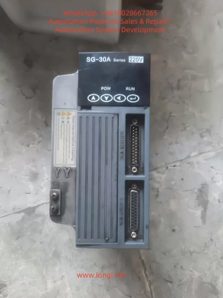
Operation Panel Function Introduction
Operation Panel Overview
The operation panel of the SG-30A series drive consists of a 6-digit LED display and 4 buttons (↑, ↓, ←, Enter). It is used to display system status, set parameters, and perform various operations. The panel features a simple and intuitive design, with a hierarchical operation mode that makes parameter setting and system monitoring more convenient.
Display Functions
- System Status Display: The operation panel can display various system status information, including motor speed, current position, accumulated command pulses, position deviation, motor torque, motor current, linear speed, rotor absolute position, command pulse frequency, operating status, and input/output terminal signals.
- Alarm Information Display: When a system fault or abnormality occurs, the operation panel will display corresponding alarm codes to help users quickly locate the problem. For example, alarm codes Err-15 and Err-30 correspond to faults such as photoelectric encoder connection errors and encoder Z-pulse loss, respectively.
Button Settings
- ↑ and ↓ Buttons: Used to increase or decrease numerical values or select different menu items. In parameter setting mode, long-pressing allows for rapid increment or decrement.
- ← Button: Represents hierarchical backtracking or cancellation of operations. During parameter setting, pressing the ← button returns to the previous menu level or cancels the current modification.
- Enter Button: Represents entering, confirming, or advancing operations. In menu selection mode, pressing the Enter button enters the selected submenu; in parameter setting mode, pressing the Enter button confirms the modification and saves it.
Jog and Manual Testing Procedures
Jog Operation (JOG Running)
Jog operation allows users to control the motor’s short-term operation through buttons, commonly used for equipment debugging and manual positioning.
Wiring
- Ensure that the main circuit terminals (R, S, T) are connected to a three-phase AC220V power supply.
- Connect the control voltage terminals (r, t) to a single-phase AC220V power supply.
- Connect the encoder signal connector CN2 to the servo motor.
- Connect the control signal connector CN1 as shown in the diagram, ensuring that at least the servo enable (SON) signal is connected.
Operation Procedure
- Pre-power Check: Confirm that all wiring is correct, the motor is unloaded, and securely fastened.
- Power On: Turn on the control circuit power and main circuit power; the POWER indicator lights up.
- Parameter Setting:
- Press the Enter button to enter the first-level menu and select “Jr-” (JOG operation mode).
- Press the Enter button again to enter the JOG operation parameter setting interface and set the JOG operation speed (parameter PA21).
- JOG Operation:
- After confirming there are no alarms, turn the servo enable (SON) ON; the RUN indicator lights up.
- Press and hold the ↑ button to run the motor forward at the JOG speed; release the button to stop the motor.
- Press and hold the ↓ button to run the motor in reverse at the JOG speed; release the button to stop the motor.
Manual Speed Adjustment Operation
Manual speed adjustment operation allows users to adjust the motor’s operating speed through buttons, commonly used for speed debugging and performance testing.
Wiring
The wiring is the same as that for jog operation.
Operation Procedure
- Pre-power Check: The same as for jog operation.
- Power On: Turn on the control circuit power and main circuit power; the POWER indicator lights up.
- Parameter Setting:
- Press the Enter button to enter the first-level menu and select “Sr-” (speed test run mode).
- Press the Enter button again to enter the speed test run parameter setting interface. No additional speed command setting is required as the speed will be adjusted in real-time through the buttons.
- Manual Speed Adjustment:
- After confirming there are no alarms, turn the servo enable (SON) ON; the RUN indicator lights up.
- Press the ↑ button to increase the speed command, and the motor speed increases; press the ↓ button to decrease the speed command, and the motor speed decreases.
Forward/Reverse Control in Position and Speed Modes
Forward/Reverse Control in Position Mode
Position mode controls the motor’s position by receiving external pulse commands, suitable for applications requiring precise positioning.
Wiring
- Main Circuit Terminals: Connect a three-phase AC220V to the R, S, T terminals.
- Control Voltage Terminals: Connect r and t to a single-phase AC220V power supply.
- Encoder Signal: Connect CN2 to the servo motor.
- Control Signals:
- Connect PULS+ and PULS- of CN1 to the positive and negative poles of the position command pulse, respectively.
- Connect SIGN+ and SIGN- to the positive and negative poles of the direction command signal, respectively.
- Connect SON to the servo enable signal.
- If necessary, connect signals such as ALRS (alarm clear), RSTP (CW drive inhibit), and FSTP (CCW drive inhibit).
Parameter Setting
- Control Mode Selection (PA4): Set to 0 (position control mode).
- Electronic Gear Setting (PA12, PA13): Set an appropriate electronic gear ratio according to the transmission ratio and encoder resolution to achieve precise position control.
- Position Command Smoothing Filter (PA19): Set according to actual needs to reduce the impact of sudden changes in command pulses on the system.
Forward/Reverse Control
- Forward Rotation: Send a forward pulse command (PULS+ is positive, PULS- is negative) and a forward direction signal (SIGN+ is high, SIGN- is low) through an external controller.
- Reverse Rotation: Send a reverse pulse command (PULS+ is negative, PULS- is positive) and a reverse direction signal (SIGN+ is low, SIGN- is high) through an external controller.
Forward/Reverse Control in Speed Mode
Speed mode controls the motor’s speed and direction by receiving external analog speed commands or internal speed commands, suitable for applications requiring continuous speed adjustment.
Wiring
- Main Circuit Terminals: The same as in position mode.
- Control Voltage Terminals: The same as in position mode.
- Encoder Signal: The same as in position mode.
- Control Signals:
- If using an external analog speed command, connect VIN+ and VIN- to the analog speed command source.
- Connect SON to the servo enable signal.
- If necessary, connect signals such as ALRS, RSTP, and FSTP.
- If using an internal speed command, select the internal speed through parameter setting.
Parameter Setting
- Control Mode Selection (PA4): Set to 1 (speed control mode).
- Internal/External Speed Command Selection (PA22): Set to 0 (internal speed) or 1 (external analog speed command).
- Analog Speed Command Gain (PA43): Set an appropriate gain value according to the analog command voltage range.
- Analog Speed Command Direction Inversion (PA44): Set according to actual needs to determine whether to invert the speed command direction.
Forward/Reverse Control
- Forward Rotation:
- If using an internal speed command, select a forward internal speed through parameter setting (e.g., SC1=0, SC2=0 selects internal speed 1, and internal speed 1 is set to a forward speed).
- If using an external analog speed command, send a positive voltage signal to VIN+ and VIN-; the voltage value determines the motor speed, and the direction is determined by the PA44 parameter (usually, a positive voltage corresponds to forward rotation).
- Reverse Rotation:
- If using an internal speed command, select a reverse internal speed through parameter setting (e.g., SC1=1, SC2=0 selects internal speed 2, and internal speed 2 is set to a reverse speed).
- If using an external analog speed command, send a negative voltage signal to VIN+ and VIN- (or send a positive voltage according to the PA44 setting to achieve reverse rotation); the voltage value determines the motor speed.
Conclusion
Through the detailed explanations in this document, users should have mastered the function introduction of the operation panel, jog and manual testing procedures, and forward/reverse control methods in position and speed modes for the Baigela Servo SG-30A series drive. In practical applications, users should set parameters and perform wiring reasonably according to specific needs to fully leverage the performance advantages of the drive. Additionally, it is recommended that users regularly consult the user manual for the latest information and technical support to ensure stable system operation and efficient production.