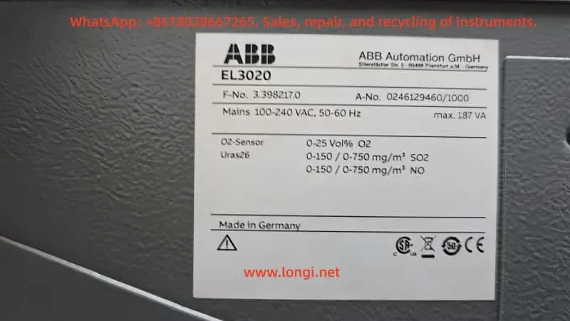
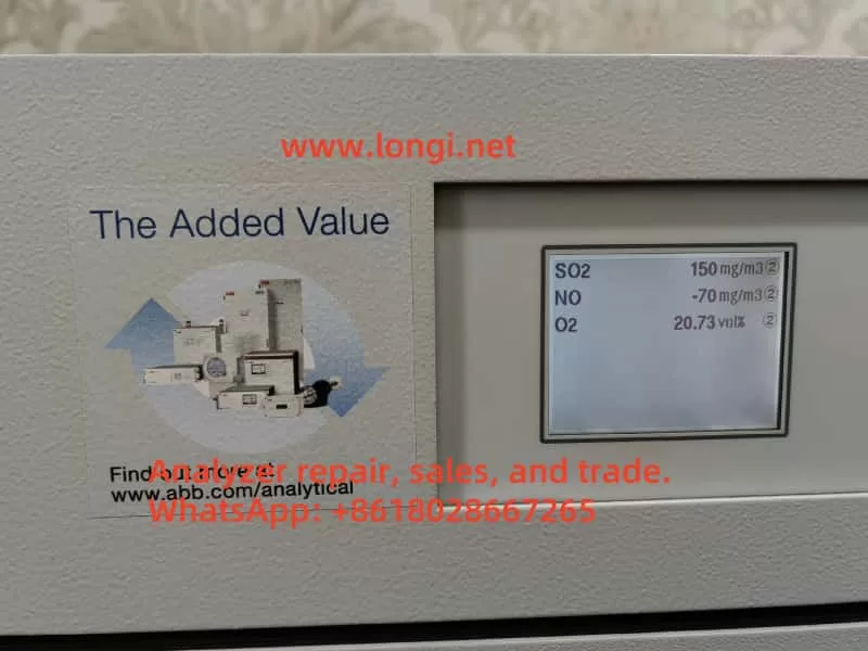
In industrial flue gas monitoring, process gas analysis, environmental emission control, and chemical process measurement, the ABB EL3000 / EL3010-C gas analyzer is a widely used online analytical instrument. When configured with a Uras26 infrared analyzer module, it can measure infrared-active gases such as SO₂, CO₂, CO, NO, CH₄, and other process components. Because this type of analyzer involves optical detection, sample cells, temperature compensation, pressure compensation, EEPROM data sets, internal calibration cells, and external span gas calibration logic, a calibration failure should never be judged from one parameter alone.
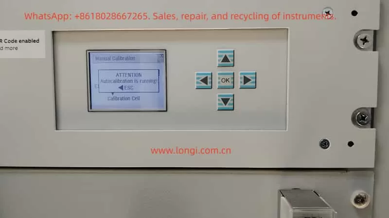
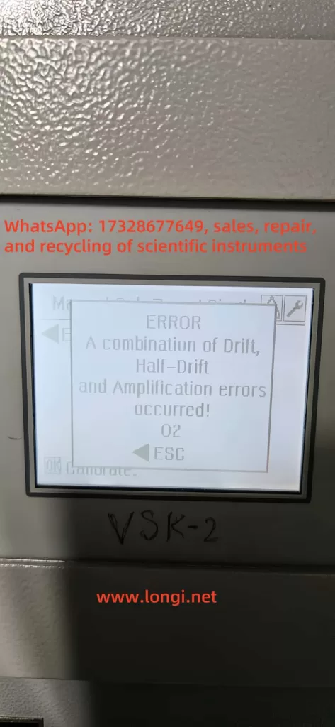
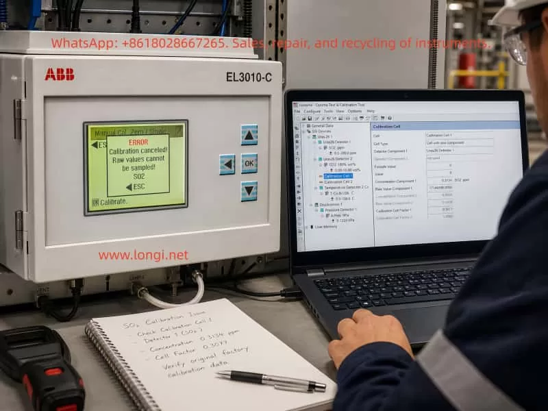
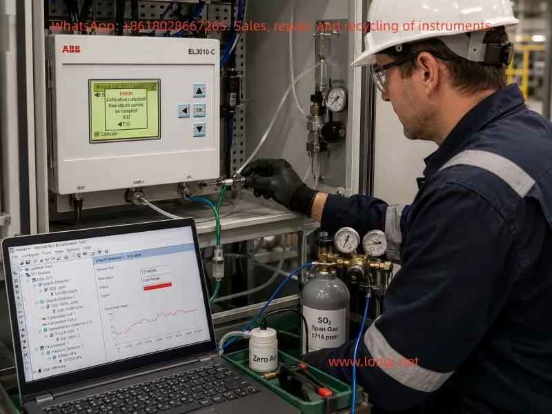
A typical case involves an ABB EL3010-C gas analyzer that failed during SO₂ calibration. Two phenomena appeared at the same time. First, in ABB Optima TCT software, the Calibration Cell 1 parameter showed an apparently abnormal SO₂ concentration component, approximately 0.3134 ppm. Second, when manual zero calibration was performed from the analyzer front panel, the analyzer displayed the following error:
ERROR
Calibration canceled!
Raw values cannot be sampled!
SO2
Many technicians may see the first symptom and immediately conclude that the SO₂ calibration cell concentration is wrong, or that the EEPROM data is corrupted. However, from a troubleshooting perspective, the second message is more important. It means the analyzer cannot acquire a valid raw signal from the SO₂ channel during calibration. Therefore, this problem should not be treated simply as a wrong concentration value in the TCT configuration. The correct diagnostic sequence should be: verify whether the raw signal is valid, check detector status, confirm gas flow and calibration conditions, verify pressure and temperature compensation, and only then investigate whether the configuration data or EEPROM data set is corrupted.
1. Basic Working Logic of ABB EL3010-C and the Uras26 Module
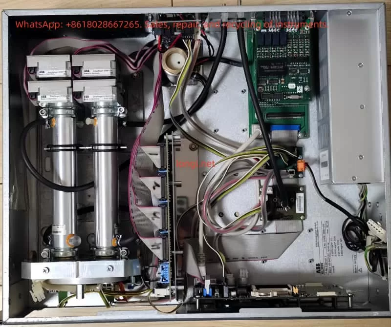
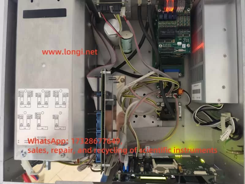
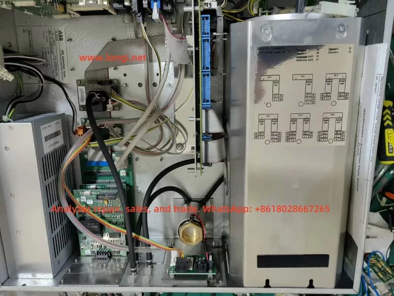
The ABB EL3010-C belongs to the ABB EL3000 / Advance Optima family of gas analyzers. Depending on configuration, the system may include a Uras26 infrared analyzer module, pressure sensor, temperature compensation unit, sample gas handling components, I/O modules, and a system controller.
The Uras26 is a nondispersive infrared gas analyzer module. Its basic principle is that infrared light passes through a sample gas cell. Different gas molecules absorb infrared energy at specific wavelengths. The detector receives the remaining light intensity, and this detector signal changes according to gas concentration. The analyzer then applies linearization, temperature compensation, pressure compensation, cross-sensitivity correction, and other algorithms to convert the raw detector signal into a displayed concentration value.
For service work, three types of data must be clearly distinguished.
The first type is the raw value, meaning the original detector signal or internal raw count. It is not ppm, not vol%, and not the final gas concentration. It is the basic signal used by the analyzer for calculation.
The second type is the measured value, meaning the calculated gas concentration after internal processing, such as SO₂ ppm or CO₂ vol%.
The third type is configuration and calibration data, including detector configuration, gas component settings, measurement ranges, calibration cell parameters, calibration factors, compensation parameters, and linearization data. These values are usually stored in the module EEPROM or related memory.
When the analyzer reports “Raw values cannot be sampled,” the message directly points to the first type of data. The SO₂ channel cannot provide a valid raw value for the calibration algorithm. At this stage, even if a calibration cell concentration value looks suspicious in TCT, it should not immediately be treated as the root cause.
2. The Role of Optima TCT: Not a Simple Routine Calibration Tool
ABB Optima TCT stands for Test & Calibration Tool. It connects to ABB Advance Optima analyzer modules and can read data sets from the module EEPROM. It can also save, archive, configure, test, and write data sets back to the module. In the TCT tree structure, a technician may see items such as General Data, Uras26 Detector, SO₂ component, measurement range, temperature detector, pressure detector, and Calibration Cell.
In field service, TCT is useful mainly for the following tasks:
- Reading and saving the original EEPROM configuration data;
- Checking the relationship between detectors, components, ranges, and calibration cells;
- Checking raw values, component values, and status codes;
- Checking pressure and temperature compensation values;
- Testing pumps, valves, module communication, and detector status;
- Restoring or correcting configuration data after confirming the correct data source;
- Comparing data set changes before and after calibration.
However, TCT should not be understood as the tool that must be used for daily zero and span calibration. In normal maintenance, routine zero calibration and span calibration are usually performed from the analyzer front panel, through the automatic calibration sequence, or through a plant control system. TCT is more suitable for engineering configuration, deeper diagnostics, data backup, and data recovery.
Therefore, when a customer asks, “How do you configure such gas analyzers?” the accurate answer is:
Routine zero and span calibration should normally be performed from the analyzer menu. TCT is mainly used to read, back up, inspect, and restore configuration data. When calibration from the analyzer menu fails, when parameters appear corrupted, or when module configuration is suspicious, TCT is then used to analyze EEPROM data sets and module status.
3. Calibration Cell Concentration Is Not the Same as External Span Gas Concentration
In this case, the TCT screen showed Calibration Cell 1 configured approximately as follows:
- Cell Type: Cell with one component;
- Detector Component 1: Uras26 Detector 1;
- Component: SO₂ ppm;
- Concentration Component 1: approximately 0.3134 SO₂ ppm;
- Raw Value Component 1: approximately 1714596;
- Calibration Cell Factor 1: approximately 0.3077.
Since the SO₂ measuring range was 0–200 ppm, many technicians would consider 0.3134 ppm unreasonable. From practical experience, this value does look suspicious for a 0–200 ppm SO₂ range. However, one point must be emphasized: the Calibration Cell concentration component is not the same as the external SO₂ span gas concentration, and it is not the live SO₂ reading.
An internal calibration cell is usually an internal optical reference, such as a reference gas cell or an equivalent absorption element inserted into the infrared optical path. It simulates a known absorption effect so that the analyzer can check or correct drift. Its parameters must match the exact analyzer, exact detector, exact calibration cell certificate, and original factory data. A technician should never simply replace this value with 50 ppm, 100 ppm, or any other span gas concentration just because the value looks wrong.
If the goal is to calibrate SO₂ using an external standard gas cylinder, the correct target is the analyzer’s zero/span calibration menu, not manual modification of the Calibration Cell concentration in TCT.
Therefore, the 0.3134 ppm value in Calibration Cell 1 should be treated as a suspicious parameter, but not as a confirmed fault by itself. The technician must first confirm:
- Whether this analyzer physically has an internal calibration cell installed;
- Whether Calibration Cell 1 really belongs to SO₂;
- Whether Calibration Cell 2 belongs to another detector or component;
- What the original factory equivalent concentration of the cell should be;
- Whether the calibration cell factor was modified;
- Whether the current data set truly belongs to this analyzer;
- Whether someone previously wrote another analyzer’s data set into this module.
Without this information, EEPROM data should not be modified.
4. “Raw Values Cannot Be Sampled” Is the Core Diagnostic Clue
The analyzer front panel displayed:
Calibration canceled!
Raw values cannot be sampled!
SO2
This message is more diagnostically important than the concentration component shown in TCT. It means that during SO₂ calibration, the analyzer attempted to acquire the SO₂ raw signal, but the sampling failed or the sampled value was invalid. As a result, the calibration was canceled.
This type of error usually comes from several main categories.
4.1 Sample Gas Flow Problems
During calibration, zero gas or span gas must actually enter the analyzer sample cell. If the gas does not enter the analyzer, or if the flow is unstable, the analyzer cannot acquire a stable raw value.
Common causes include:
- Zero gas not opened;
- Abnormal outlet pressure from the gas cylinder regulator;
- Too low gas flow;
- Inlet pressure too high or too low;
- Blocked sample filter;
- Blocked exhaust outlet;
- Internal sample pump not working;
- Solenoid valve not switching to the correct gas path;
- Tubing connected incorrectly;
- Condensate inside the sample cell;
- Sample gas path blocked by sulfate deposits, dust, or corrosion products.
Online SO₂ analyzers are especially vulnerable to acidic condensate and dust contamination. If the sample conditioning system fails, moisture, acid mist, sulfur compounds, and particles may enter the sample cell. Mild contamination may cause drift, while severe contamination may attenuate the optical path or block the gas path.
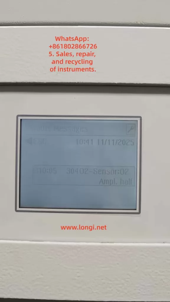
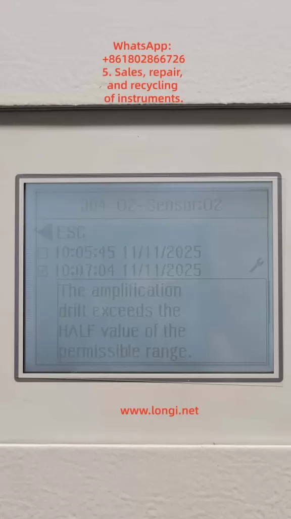
4.2 Abnormal Raw Signal from Uras26 Detector 1
If SO₂ is assigned to Uras26 Detector 1, failure to sample raw values may indicate a problem in the detector signal chain.
Typical symptoms include:
- Raw value is zero or extremely low;
- Raw value remains frozen;
- Raw value exceeds the ADC range;
- Raw value fluctuates violently;
- Detector status code is abnormal;
- Analyzer shows overrange, underrange, invalid value, or alarm indication;
- Calibration cannot reach a stable condition.
Possible causes include infrared source aging, infrared source failure, chopper malfunction, detector aging, preamplifier failure, ADC acquisition fault, loose signal connection, module power problem, or severe contamination of the sample cell.
4.3 Optical System Contamination or Attenuation
The Uras26 measurement depends on a stable infrared optical path. If the source, mirror, window, sample cell, or detector optical path is contaminated, the detector signal will be reduced or distorted. In SO₂ applications, optical contamination is relatively common, especially when sample conditioning is poor. Moisture, acid mist, dust, and reaction products can deposit on optical windows.
If optical attenuation becomes severe, the analyzer may still display some value in measurement mode, but during calibration it may fail to satisfy the required stability, intensity range, or algorithm conditions. The result can be “Raw values cannot be sampled.”
4.4 Temperature or Pressure Compensation Problems
Infrared gas absorption is affected by temperature and pressure. In an EL3010-C / Uras26 configuration, temperature and pressure compensation are often present. In the TCT tree, this may appear as items such as T-Con U26 C and A.Pres hPa. If temperature or pressure measurements are invalid, the final SO₂ calculation may also become invalid, and calibration may be blocked.
The following points should be checked:
- Whether the pressure value is reasonable, such as close to atmospheric pressure or within the expected process range;
- Whether the temperature value is reasonable;
- Whether the pressure sensor has an alarm;
- Whether the temperature compensation status is normal;
- Whether the compensation items are configured correctly;
- Whether the pressure or temperature value is used in the current SO₂ range calculation.
If the pressure sensor is open-circuit, short-circuit, out of range, or incorrectly configured, the analyzer may be unable to calculate a valid SO₂ value.
4.5 Configuration Data or EEPROM Data Set Problems
If hardware and gas flow are normal, but TCT shows logical inconsistencies between detector, component, measurement range, and calibration cell configuration, the EEPROM data set may have been modified incorrectly or corrupted.
Common situations include:
- A technician wrote another analyzer’s data set into this module;
- A CPU board or memory device was replaced but the correct data set was not restored;
- Calibration cell settings were modified incorrectly in the full version of TCT;
- Detector 1 / Detector 2 assignment does not match SO₂ / CO₂ component assignment;
- Measurement range is missing;
- Correction function points to a non-existent component;
- Calibration cell points to the wrong detector;
- Data set is incompatible with the actual module type;
- EEPROM memory is unstable.
However, EEPROM failure should not be the first assumption. It should be investigated only after gas flow, detector raw value, pressure, temperature, and optical condition have been checked.
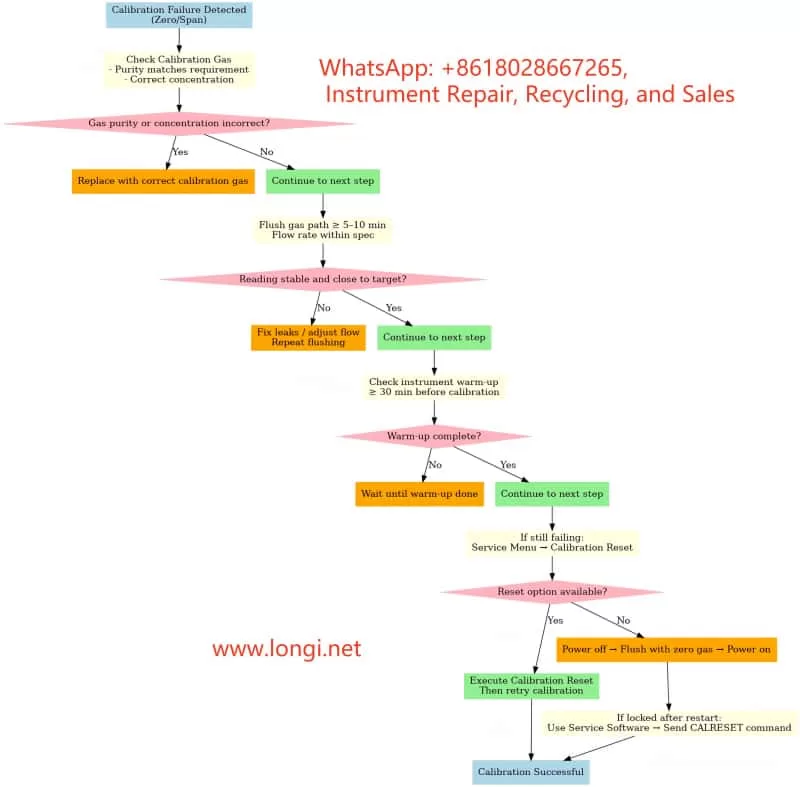
5. Correct Troubleshooting Sequence: Do Not Modify Parameters First
The worst response to this type of problem is to directly modify the concentration component in TCT and write it back to EEPROM. This may destroy recoverable original data and turn a calibration problem into a serious configuration problem.
A safer diagnostic process is as follows.
Step 1: Fully Back Up the Current Data Set
After connecting TCT, read the module data and save it immediately. The saved file extension depends on the module type. Analyzer module files are commonly saved as a format such as .d04. The automatic backup copy generated by TCT should also be preserved.
At minimum, save two files:
- Original file before testing;
- File after zero calibration or after the error occurs.
If it is necessary to determine whether a parameter “changed by itself,” the conclusion must be based on a comparison of before-and-after data files, not memory or screenshots alone.
Step 2: Do Not Write to EEPROM
Before the fault is confirmed, do not execute Send Module Data and do not write any modified data back to the analyzer module. This is especially important for Calibration Cell, Detector, Component, Range, and Correction Function settings.
Step 3: Use Module Test View to Check Real Status
The Module Test View in TCT is the most important diagnostic screen in this case. The following values should be checked:
- Uras26 Detector 1 raw value;
- Uras26 Detector 1 status;
- SO₂ component measured value;
- SO₂ percentage of range;
- SO₂ status code;
- Active correction functions;
- Pressure value;
- Temperature value;
- Pump and valve test status.
If the SO₂ raw value is missing, frozen, overrange, or has an abnormal status, the problem already exists before calibration. In that case, there is no point focusing only on calibration cell concentration.
Step 4: Confirm Zero Gas and Flow
Before performing zero calibration, confirm that the zero gas source is correct. SO₂ zero calibration is usually performed with high-purity nitrogen or suitable zero gas. Clean air may be acceptable in some applications, but only if it meets the analyzer and process requirements.
The following field checks are necessary:
- Whether zero gas is connected to the correct inlet;
- Whether flow rate meets analyzer requirements;
- Whether the outlet is open;
- Whether the internal pump is operating;
- Whether solenoid valves are switching correctly;
- Whether the sample conditioning system is dry and clean;
- Whether there is condensate or blockage.
If the gas path is not open, the analyzer cannot sample a stable raw value.
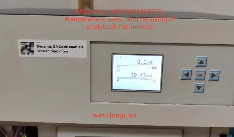
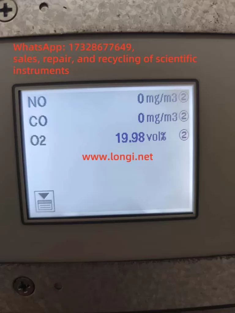
Step 5: Observe Whether SO₂ Is Valid in Measurement Mode
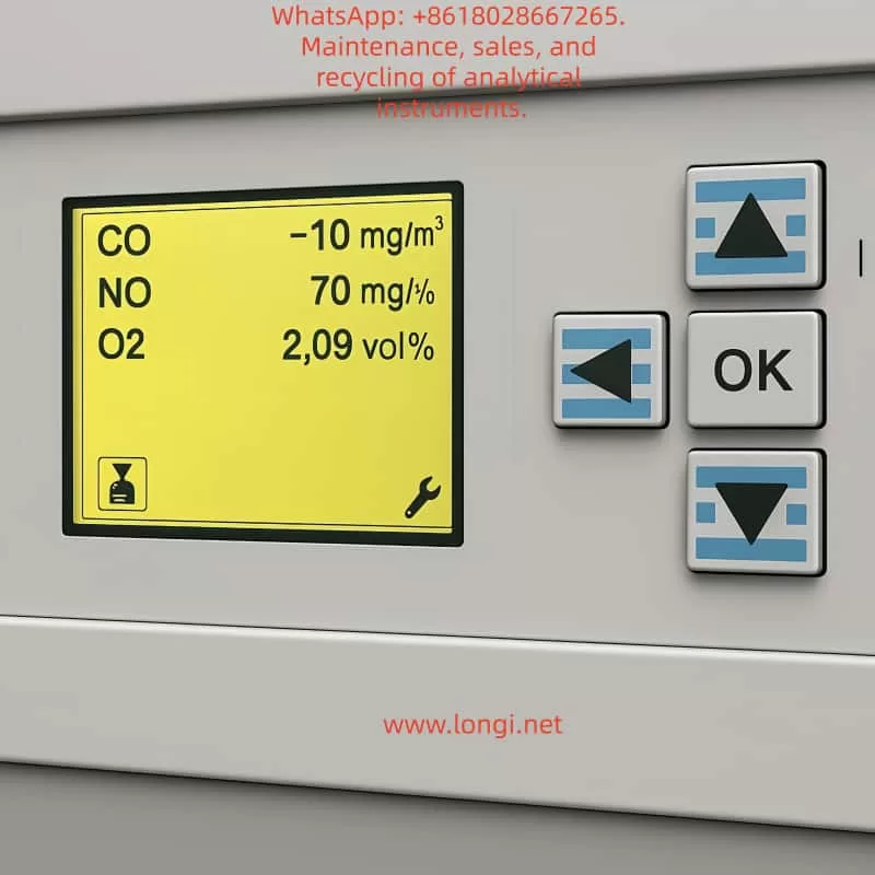
Before repeating calibration, check whether SO₂ is displayed normally in measurement mode. If SO₂ is already invalid, unstable, overrange, or constantly negative in measurement mode, the problem is not the calibration operation itself. The detection chain already has an issue.
The symptoms can be interpreted as follows:
- SO₂ value is stable in measurement mode, but calibration fails: likely calibration condition, stability judgment, or configuration problem;
- SO₂ value is unstable: likely gas flow fluctuation, optical source problem, or detector issue;
- SO₂ value is overrange: possible wrong gas concentration, optical contamination, configuration error, or real contamination;
- SO₂ value is invalid: prioritize raw value, ADC, pressure, and temperature compensation checks;
- SO₂ value remains frozen: possible signal chain freeze or data update failure.
Step 6: Check Pressure and Temperature Compensation
Verify whether pressure and temperature values are within reasonable ranges. If pressure or temperature is abnormal, correct the compensation signal first. Otherwise, even a healthy SO₂ detector may produce invalid calculated concentration.
Step 7: Only Then Investigate Calibration Cell Configuration
Only after raw value, gas flow, pressure, temperature, and SO₂ measurement stability are confirmed should Calibration Cell 1 and Calibration Cell 2 be investigated.
At that point, check:
- Whether Calibration Cell 1 should be assigned to SO₂;
- Whether Calibration Cell 2 should be assigned to CO₂;
- Whether Cell Type is correct;
- Whether Detector Component 1 / 2 are correct;
- Whether Concentration Component matches original factory data;
- Whether Calibration Cell Factor is reasonable;
- Whether an original backup data set is available for recovery.
Without an original certificate or backup, calibration cell parameters should not be reconstructed by guesswork.
6. How to Judge Whether EEPROM or Memory Is Faulty
When a parameter appears to change unexpectedly, technicians often suspect EEPROM failure. This is possible, but evidence is required.
A real EEPROM or memory data problem usually shows symptoms such as:
- Parameters are lost after power cycling;
- The same data reads differently each time;
- Serial number, module type, detector configuration, or range configuration becomes abnormal;
- Different screens show contradictory component, range, or detector logic;
- TCT reports errors such as data not compatible, unknown index, invalid subindex, or module data incorrect;
- Before-and-after file comparison shows irregular changes in non-calibration configuration fields;
- Write verification fails;
- The analyzer randomly reports configuration errors or module identification errors.
If only zero correction, drift, raw reference, or offset-related values change after zero calibration, that may be part of the normal calibration process and does not prove EEPROM failure.
The correct method is data comparison:
- Read the module data with TCT and save it as
before_zero; - Take screenshots of Calibration Cell 1, Calibration Cell 2, SO₂ component, range, and Module Test View;
- Perform zero calibration from the analyzer front panel;
- Re-read the module data from the module, instead of opening the old file;
- Save it as
after_zero; - Compare the two files and screenshots.
If changes are mainly limited to zero, drift, calibration result, or correction values, they may be normal or calibration-related. If nominal Calibration Cell concentration, Detector assignment, Range definition, Component name, or similar configuration fields change without reason, then corrupted data or memory instability becomes much more likely.
7. Relationship Between External Gas Calibration and Internal Calibration Cell
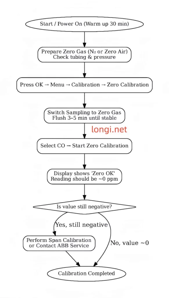
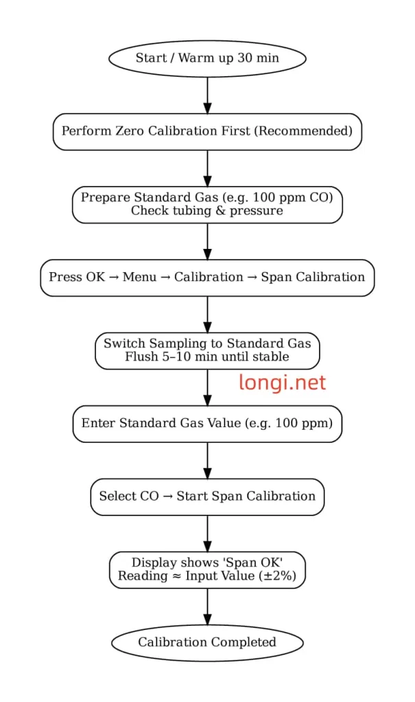
For a 0–200 ppm SO₂ measuring range, reliable calibration is usually based on external standard gas. A typical procedure is:
- Introduce zero gas;
- Wait until SO₂ measured value and raw value are stable;
- Perform zero calibration;
- Introduce certified SO₂ span gas;
- Wait until the reading is stable;
- Perform span calibration or end-point calibration;
- Recheck zero gas;
- Recheck span gas;
- Record calibration deviations before and after adjustment.
The span gas concentration should be selected according to the range. For a 0–200 ppm range, a span gas around 50% to 90% of full scale is commonly used, such as 100 ppm, 150 ppm, or 160 ppm, depending on site rules, analyzer instructions, and metrology requirements.
The internal calibration cell is usually used for drift checking, internal verification, or certain automatic calibration functions. It should not be treated as a complete substitute for external standard gas, especially after repair, optical contamination, detector replacement, suspected data corruption, or long-term drift.
8. Reasonable Fault Chain in This Case
Based on the observed symptoms, the more reasonable fault chain is:
The SO₂ channel cannot provide a valid raw value during calibration
→ The front-panel zero calibration is canceled
→ Calibration Cell 1 or related values in TCT appear abnormal
→ The field technician assumes the Calibration Cell 1 concentration is wrong
→ The actual root cause may be SO₂ raw signal acquisition, gas flow, optical condition, pressure/temperature compensation, or data set consistency.
Therefore, the most important next step is not to modify the 0.3134 ppm value. The priority is to obtain the SO₂ raw value and status code from Module Test View. Without this information, it is impossible to determine whether the root cause is gas path failure, detector failure, optical contamination, pressure/temperature compensation failure, or EEPROM data corruption.
9. Service Conclusion and Recommended Handling
When an ABB EL3010-C / Uras26 gas analyzer reports “Calibration canceled! Raw values cannot be sampled! SO2,” the following principles should be followed.
First, back up data before making any change.
The data set read by TCT is the basis for recovery and comparison. Any write-back action must be performed only after confirming that the data is correct.
Second, check raw value before checking concentration.
The SO₂ displayed concentration is a calculated result. The raw value is the foundation of whether calibration can proceed.
Third, check gas flow before suspecting the circuit board.
Whether zero gas actually enters the analyzer, whether flow is stable, whether the sample cell is blocked, and whether valves and pumps are working are often overlooked but critical.
Fourth, check pressure and temperature compensation before judging the SO₂ algorithm.
Abnormal pressure and temperature values can directly affect gas concentration calculation and calibration validity.
Fifth, do not modify Calibration Cell parameters casually.
The internal calibration cell concentration is not the external span gas concentration. It must be confirmed using the original certificate, backup file, or factory data.
Sixth, EEPROM failure must be proven.
Memory or EEPROM should be strongly suspected only when parameters read inconsistently, configuration fields change without reason, data is lost after power cycling, incompatible data messages appear, or module identification becomes abnormal.
10. Summary
For an ABB EL3010-C / Uras26 gas analyzer, calibration problems should not be judged only by one concentration value or one TCT parameter. An abnormal SO₂ concentration component under Calibration Cell 1 is worth investigating, but the front-panel message “Raw values cannot be sampled! SO2” is the more direct and important diagnostic clue. It means the SO₂ channel cannot provide a valid original signal during calibration, so the calibration algorithm cannot continue.
The correct troubleshooting strategy is to examine SO₂ raw value, detector status, gas flow, optical condition, pressure and temperature compensation, and configuration data consistency step by step. TCT should be used as a diagnostic and backup tool, not as an entry point for blind parameter modification. Only after hardware, gas path, raw signal, and compensation values are confirmed should Calibration Cell configuration be corrected, and only with reliable original data.
For high-precision gas analyzers, the most dangerous service action is not a temporary calibration failure. The real danger is writing new EEPROM data without backup or evidence. The proper method is to save the original data first, then use Module Test View to identify why the SO₂ raw value cannot be sampled. This approach prevents a diagnosable calibration fault from becoming a much more complicated configuration corruption problem.