Posted on

From F2044 to F2042: Offline Diagnosis, Communication Identification, and Safe Bench Testing of a Bosch Rexroth IndraDrive C Dual-Encoder Servo System

In paper machinery, winding equipment, printing lines, coating machines, textile machinery, metal processing lines, and continuous feeding systems, a high-power servo drive often does much more than simply rotate a motor. It may also participate in speed synchronization, tension control, line-speed measurement, measuring-roll feedback, position compensation, and machine interlocking.

Therefore, when a Bosch Rexroth IndraDrive C system is removed from a customer’s machine and brought to a repair workshop, it usually cannot be tested like an ordinary inverter. Supplying three-phase power, 24 V control power, and connecting the motor is often not enough to make the drive run. The real difficulty is not only determining whether the power module is damaged, but also understanding the original control architecture, encoder topology, external I/O supply, serial communication control, and parameter logic.

This is especially true for an IndraDrive C system equipped with a configurable control section, X15 parallel I/O interface, X2 serial communication, and an external measuring-roll encoder. During startup, the drive checks several conditions in sequence. After one fault is removed, the next deeper-level fault may appear. For example, when F2044 is cleared and F2042 appears afterward, this does not necessarily mean a new fault has been created. It often means the drive has passed the previous external I/O power check and has now started checking the encoder feedback chain.

This article uses a typical HCS03.1 high-power IndraDrive C system with a CSB01.1C control section, external measuring encoder, and PLC serial control architecture as an example. It explains how to diagnose the drive offline, identify the real function of each interface, understand F2044 and F2042, connect IndraWorks Ds through X2, avoid unsafe parameter changes, and establish a safe temporary bench-test method.
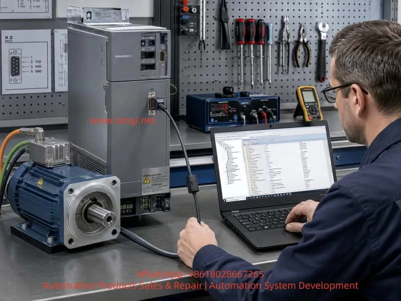

Bosch Rexroth IndraDrive C servo drive and industrial motor connected on a repair bench, with a technician using a laptop for parameter diagnostics through the X2 serial interface.

1. IndraDrive C Is Not an Ordinary VFD

A Bosch Rexroth IndraDrive C drive consists of a power section and a control section. The power section handles three-phase rectification, DC bus energy, inverter output, braking chopper operation, thermal management, and motor power output. The control section handles motion control, encoder evaluation, digital I/O, communication, diagnostics, parameter management, and interaction with PLC or CNC systems.

For example, the drive model:

HCS03.1E-W0150-A-05-NNBV

belongs to the high-power compact IndraDrive C series. It is typically used for large main drives, winding rollers, drawing rollers, tension-control systems, and other high-torque servo applications. This type of drive must not be treated like a small servo amplifier or a basic frequency inverter during bench testing.

A key point is that the same HCS03 power section can be fitted with different control sections. The control section determines which interfaces and functions are available: serial communication, Profibus, SERCOS, analog input, parallel I/O, encoder options, positioning mode, spindle mode, or speed synchronization.

Therefore, before testing the drive, the technician must identify three things:

Power section model
Control section model
Firmware and parameter set

Looking only at the power section model is not enough. The real control logic is determined by the control section, firmware, and application parameters.


2. Correctly Identifying X2, X4, X8, and X15

In this case, the control section model is:

CSB01.1C-PL-ENS-EN2-...

The important parts are:

CSB01.1C = configurable single-axis control section
PL       = parallel interface option
ENS      = standard encoder interface
EN2      = second encoder / optional encoder interface

This means the drive is not a simple fixed-I/O unit. It is a configurable drive that can be controlled through communication, mapped I/O, and encoder functions.

The important connectors are:

X2   = RS232 serial interface
X15  = parallel I/O interface
X4   = optional encoder / measuring encoder interface
X8   = motor encoder or standard feedback interface

In the customer’s electrical drawing, the system uses two encoders:

X8 → motor encoder
X4 → measuring-roll encoder

This means the motor encoder and measuring encoder are both part of the original system. The motor encoder is used for motor feedback, speed control, and commutation. The measuring-roll encoder is likely used for actual material speed, length measurement, synchronization, or tension-related control.

If only the motor and drive are brought to the workshop while the measuring-roll encoder remains on the machine, the drive may report an encoder-related fault because the original parameter set still expects Encoder 2 to exist.
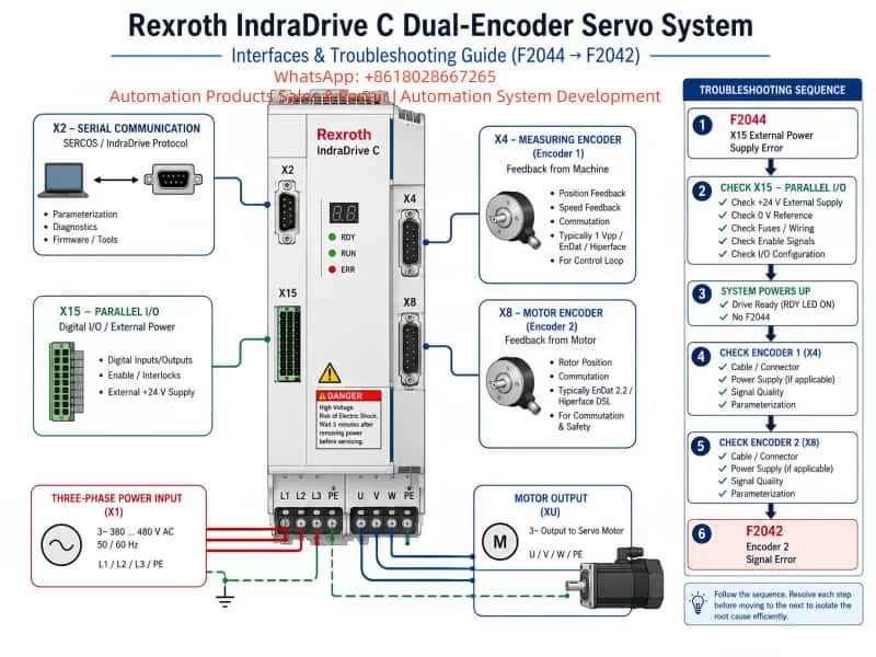

Technical diagram of a Rexroth IndraDrive C dual-encoder servo system showing X2 serial communication, X15 parallel I/O power supply, X4 measuring encoder, X8 motor encoder, three-phase input, motor output, and F2044 to F2042 troubleshooting sequence.

3. F2044 and F2042 Must Be Understood as Sequential Diagnostics

When the drive is powered on without the required X15 external I/O supply, it may display:

F2044
External power supply X15 error

This means the X15 external I/O power supply is missing, incorrect, or not detected. For a control section with a parallel interface, X15 is not just an optional connector. It may be used for inputs, outputs, enable chains, interlocks, status signals, and machine logic.

After the X15 external 24 V supply is connected correctly, F2044 may disappear. Then the drive continues checking the next required conditions. If the next displayed fault is:

F2042
Encoder 2: encoder signals incorrect

this usually means the drive has now detected a problem with the second encoder channel. In this case, the second encoder corresponds to the external measuring-roll encoder that is missing from the bench setup.

This sequence is normal:

X15 not powered → F2044
X15 powered correctly → F2044 cleared
Missing Encoder 2 → F2042

Therefore, F2042 after F2044 does not automatically mean the drive or motor has been damaged. It means the diagnosis has moved to the next dependency.
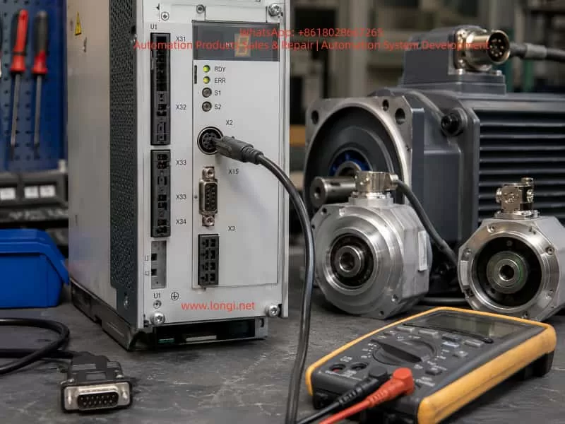

Close-up of an industrial servo drive test setup with Bosch Rexroth IndraDrive interfaces, connected encoder cables, servo motors, D-sub connector, and digital multimeter on a maintenance workbench.

4. Supplying X15 with 24 V Does Not Mean the Drive Can Run from I/O

Many technicians assume that once X15 has 24 V, the motor can be started by applying 24 V to a few digital inputs. This is not always true.

On a configurable IndraDrive control section, the physical X15 pins are only hardware inputs and outputs. Their actual function is defined by parameters. One input may be mapped as Drive ON in one project, but as a limit switch, mode selector, reset, external interlock, or PLC handshake signal in another project.

Possible functions include:

Drive ON
Drive Halt
Fault Reset
Jog +
Jog -
Forward
Reverse
External enable
Mode selection
Limit switch
PLC interlock
Status feedback

Therefore, knowing the physical pin number is not enough. The current parameter mapping must also be known.

In this case, the customer’s electrical drawing shows a PLC serial communication path:

PLC serial module
↓
RS485
↓
HAS05.1-005 RS232/RS485 converter
↓
Drive X2

This strongly suggests that the original machine does not use X15 as the main command source. Instead, the PLC probably sends the control word, speed command, enable sequence, reset, and operating mode through X2 communication.

So X15 power is required to clear F2044, but X15 may not have authority to start the motor unless the control source and I/O mapping are changed.


5. X2 Is the Key Diagnostic Interface

The X2 connector on this IndraDrive is an 8-pin Mini-DIN RS232 serial interface. It is used for:

Parameter reading
Parameter writing
Diagnostics
Fault history
DriveTop / IndraWorks communication
Serial master control
Connection to RS232/RS485 converter

The correct X2 pin assignment is:

1 = RTS
2 = CTS
3 = TxD
4 = GND
5 = RxD
6 = Vcc
7 = n.c.
8 = n.c.

For connection to a PC through RS232, the basic wiring is:

Drive X2-3 TxD → PC DB9-2 RxD
Drive X2-5 RxD → PC DB9-3 TxD
Drive X2-4 GND → PC DB9-5 GND

X2-6 is Vcc and should not be connected to the PC serial port. X2 is RS232, not TTL and not RS485. A USB-TTL adapter must not be connected directly to X2. If the computer has no real serial port, a proper USB-RS232 adapter should be used.

The original machine may use a HAS05.1-005 converter. This converter allows the PLC RS485 side to communicate with the drive’s RS232 X2 port. Therefore, the field system may look like RS485 from the PLC side, but the drive X2 itself remains RS232.


6. The Standard Four-Key Panel Cannot Replace IndraWorks Ds

The small four-key panel on the drive usually has:

Esc
Up
Down
Enter

It can be used for basic status display, fault display, simple command confirmation, and limited menu operations. However, it is not suitable for full parameter work.

It cannot reliably perform these tasks:

Export complete parameter set
View all P-0 parameters
View all S-0 parameters
Edit encoder configuration safely
Compare original and modified parameters
Change control source mapping safely
Check live X15 input status
Check serial communication status
Save and restore complete parameter files

For this case, the correct tool is:

IndraWorks Ds
or IndraWorks Engineering with drive commissioning functions

A comfort control panel may allow more parameter editing than the standard four-key panel, but for a repair workshop, software is much safer because it allows parameter backup, comparison, online diagnostics, and easier restoration.

Before changing anything, the technician should connect through X2, read the drive online, and save the original parameters.


7. Easy Startup Is a Temporary Test Method, Not a Permanent Machine Solution

IndraDrive provides an Easy Startup function for commissioning and temporary testing. When activated, it can temporarily bypass the original master communication and allow simplified local test operation.

The key point is that Easy Startup is not intended to permanently replace the original PLC or CNC logic. It is useful for bench testing because it can help verify:

Drive power section
Motor feedback
Motor rotation
Basic speed control
Low-speed operation
Fault response

However, Easy Startup cannot replace the original measuring-roll synchronization, tension control, PLC logic, line-speed control, or production process control.

For a repair bench, Easy Startup is useful only after the basic faults have been cleared:

X15 external power OK
Encoder faults resolved or temporarily configured
Motor feedback correct
Main power safe
Emergency stop available
Motor mechanically fixed

It should not be used as a permanent operating mode for the customer’s machine.


8. Encoder 2 Should Not Be Permanently Disabled Without Understanding the Machine Function

When F2042 appears, one possible temporary test method is to disable Encoder 2 in the parameter set. However, this must be treated as a temporary bench-test action only.

The external measuring encoder may be used for:

Actual material speed
Line speed measurement
Length counting
Tension control
Slip detection
Roll diameter compensation
Synchronization
Feed ratio calculation

If it is permanently disabled, the motor may run, but the machine process may become invalid or unsafe.

Possible consequences include:

Incorrect line speed
Incorrect length measurement
Unstable tension
Roll synchronization error
Material breakage
Slip not detected
Wrong feed ratio
Unexpected speed correction

A safer temporary method is to connect a compatible test encoder to X4. If the original measuring encoder used 8 wires:

+5V
0V
A / A-
B / B-
Z / Z-

then the temporary encoder must be a 5 V TTL differential or RS422 line-driver type. It must not be a 24 V encoder, NPN encoder, PNP encoder, or open-collector single-ended encoder.

Even if the electrical signals are compatible, the pulse count may be different from the original encoder. This may clear F2042 but still make the machine measurement wrong. That is acceptable only for bench testing, not for final machine operation.


9. A Correct Offline Diagnosis Sequence

For a complex IndraDrive C system, the correct sequence is more important than speed.

Step 1: Identify all hardware

Record:

Power section model
Control section model
Firmware version
Motor model
Motor encoder type
External encoder type
PLC model
Communication module
HAS05 converter model
Brake resistor
Original cable connections

Step 2: Preserve original information

Before removing or changing wires, take photos of:

X15 wiring
X2 communication cable
X4 encoder cable
X8 motor encoder cable
Motor power cable
Brake resistor cable
Main power cable
24 V wiring
Grounding
PLC terminal numbers

Step 3: Clear basic power-related faults

If F2044 is present, solve the X15 external 24 V power issue first. Do not attempt to start the drive while F2044 is active.

Step 4: Resolve encoder faults

If F2042 appears after F2044 is cleared, check whether Encoder 2 is missing, incorrectly wired, or expected by the parameter set.

Step 5: Confirm the real control source

Determine whether the drive is controlled by:

X2 serial communication
Profibus
SERCOS
Analog input
X15 parallel I/O
Easy Startup
Local software test mode

Do not assume X15 can start the drive unless the parameter mapping confirms it.

Step 6: Back up parameters before modification

Before disabling Encoder 2 or switching to local I/O control, save the full parameter set. Never perform Load Defaults or firmware updates without a backup.

Step 7: Perform only low-speed bench testing

The motor must be mechanically fixed. Use low speed, low torque, short test duration, and a real emergency stop. A high-power 30 kW motor with high torque must never be allowed to run freely on a bench.


10. Parameter Modification Principles

Any parameter change must follow four principles:

Backup first
Change as little as possible
Record original values
Restore after testing

Do not perform:

Load Defaults
Factory reset
MMC parameter loading
Firmware upgrade
Random I/O remapping
Permanent encoder disabling
Permanent control source change

Without a parameter backup, even a simple change can make the drive incompatible with the customer’s PLC program or mechanical system.

Important parameter groups include:

Encoder 1 configuration
Encoder 2 configuration
Optional encoder assignment
Control word source
Speed command source
Communication settings
I/O mapping
Operating mode selection
Drive Halt / Drive ON logic

The exact parameter names and values may vary by firmware version. Therefore, the correct procedure is to go online with IndraWorks Ds, read the current values, save the parameter file, and only then make temporary modifications.


11. “Motor Can Rotate” Does Not Mean “Machine Is Repaired”

For a high-power servo system, testing should be divided into levels.

Level 1: Drive powers up correctly

Confirm:

Display works
No fatal hardware fault
No F2044
Control section identified
Parameters readable
Software can connect

Level 2: Feedback and interlocks are valid

Confirm:

Motor encoder OK
External encoder OK or temporarily handled
Temperature feedback OK
Drive Halt status correct
Emergency stop available
Grounding correct
Main contactor logic safe

Level 3: Low-speed motor operation

Confirm:

Motor turns in the correct direction
No abnormal noise
Current is stable
Feedback is stable
No encoder jumping
No DC bus abnormality
Stop behavior normal

Level 4: Machine process operation

Confirm:

PLC communication normal
Measuring-roll feedback normal
Line-speed calculation correct
Tension stable
Synchronization correct
Original machine logic restored

Only Level 4 proves the customer’s machine is truly restored. A successful bench spin only proves that the drive and motor can run under simplified conditions.


Conclusion

The diagnosis of a Bosch Rexroth IndraDrive C high-power servo system cannot be reduced to simply applying power and forcing an enable input. A system with HCS03.1 power section, CSB01.1C control section, X15 parallel I/O, X2 serial communication, motor encoder, and external measuring encoder must be treated as a complete motion-control system.

F2044 indicates that the X15 external I/O power supply is missing or incorrect. Once it is corrected, F2042 may appear because the drive now checks Encoder 2. If the original machine uses a measuring-roll encoder on X4 and this encoder is not present during bench testing, F2042 is expected.

The proper repair method is:

Identify hardware
Preserve wiring information
Clear X15 power faults
Confirm encoder topology
Connect IndraWorks Ds through X2
Back up parameters
Temporarily configure a safe bench-test mode
Run only low-speed tests
Restore all original parameters
Verify the complete machine at the customer site

Only by understanding the relationship between power section, control section, PLC communication, X15 I/O, X2 serial interface, X4/X8 encoder structure, and the original parameter set can a technician diagnose and repair this type of IndraDrive C system safely and reliably.
Posted on

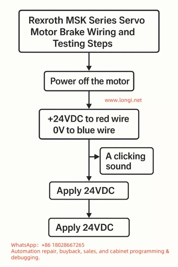
🛠 Wiring and Testing Steps for Rexroth MSK Series Servo Motor Brakes

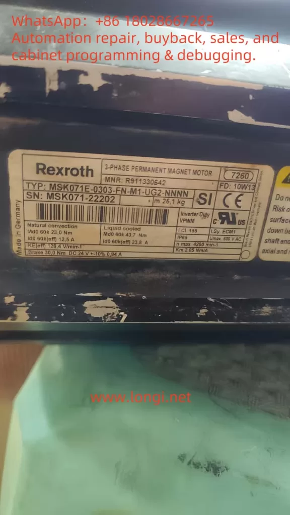
1. Confirm Motor Model and Brake Parameters

  • Model: MSK071E-0303-FN-M1-UG2-NNNN
  • Nameplate Parameters: Brake 30Ω, DC 24V ±10%, 0.94A
    👉 Indicates that this motor is equipped with a DC brake, rated for a working voltage of 24VDC, which releases the brake when powered and locks it when de-energized.

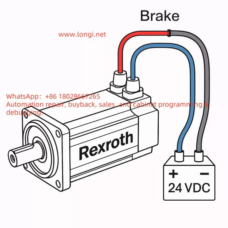
2. Wiring Identification

  • Red Wire → +24VDC
  • Blue Wire → 0V (Negative)
  • (Gray Wire Pair) = Temperature Sensor, not involved in brake testing.

3. Power Supply Preparation

  • Use a regulated 24VDC power supply with a rated current of ≥2A (reserve a margin, although normal operation requires approximately 1A).
  • The power supply should have overcurrent protection to prevent damage from short circuits.
  • If possible, it is best to use a power supply with soft start or current limiting functions.

4. Testing Steps

  1. Disconnect the motor and confirm that the motor’s main power supply is not connected.
  2. Connect the positive terminal of the power supply to the red wire and the negative terminal to the blue wire.
  3. Apply 24VDC power:
    • You should hear a “click” sound, indicating that the brake has been released.
    • Gently rotate the motor shaft by hand; it should rotate freely.
  4. Disconnect the 24VDC power supply:
    • Attempt to rotate the motor shaft again; it should be locked by the mechanical brake.

5. Precautions

  • Never operate the motor shaft for extended periods with the brake continuously powered without control from a motor driver, as excessive inertia from shaft rotation may damage the brake pads.
  • In practical applications with a driver, the brake signal is usually controlled by the driver’s Brake Output; do not continuously apply direct power.
  • If the brake fails to release, check the following:
    • Whether the power supply voltage is within 24V ±10%.
    • Whether the power supply current is sufficient.
    • Whether the red/blue wires are reversed (reversing them will prevent release).

✅ Summary:

  • Red → +24VDC, Blue → 0V
  • Power on to release, power off to lock.
  • Testing method: Listen for sound, rotate shaft.
Posted on

User Manual Guide for Bosch Rexroth VFC3610/VFC5610 Series Frequency Converters

The Bosch Rexroth VFC3610/VFC5610 series frequency converters are high-performance devices widely used in industrial automation, mechanical processing, pump and fan control, and other fields. This article provides a detailed guide on using the user manual for these frequency converters, including operating panel functions, parameter settings, and troubleshooting.

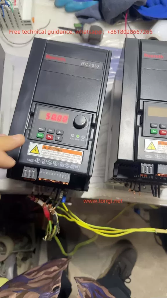
VFC3610VFC5610 physical picture

I. Operating Panel Function Introduction

1.1 Operating Panel Functions

The operating panel of the Bosch Rexroth VFC3610/VFC5610 series offers a range of functions for parameter settings, monitoring, and diagnostics. The main components include an LED display, navigation knob, function button, stop button, and run button.

  • LED Display: Shows the operating status, parameter values, and fault codes.
  • Navigation Knob: Used to select parameter groups/parameters and set parameter values.
  • Function Button (Func): Enters the parameter group screen and returns to the previous screen.
  • Stop Button (Stop): Stops the frequency converter.
  • Run Button (Run): Starts the frequency converter.

1.2 Parameter Copying

Users can copy parameter settings from one frequency converter to another using the parameter copy function:

  1. Back up parameters to the operating panel: Set parameter [b0.11] = ‘1: Backup parameters to the operating panel’.
  2. Install the operating panel on the target frequency converter.
  3. Set parameter [b0.11] = ‘2: Copy parameters from the operating panel’ to complete the parameter copying process.

1.3 Password Setting and Removal

To protect parameter settings, users can set a password. The steps for setting and removing the password are as follows:

  • Set Password: Set parameter [b0.20] to the desired user password (range: 0…65,535).
  • Remove Password: Set parameter [b0.20] to 0.

1.4 Parameter Access Restriction

To prevent unauthorized access to parameter settings, the frequency converter offers access restriction features. Users can set parameter [b0.00] to limit access rights:

  • 0: Basic parameters
  • 1: Standard parameters
  • 2: Advanced parameters
  • 3: Startup parameters
  • 4: Modified parameters

1.5 Parameter Initialization

In some cases, users may need to initialize the frequency converter parameters to their default settings. The steps are as follows:

  1. Set parameter [b0.10] = ‘1: Restore default settings’.
  2. The frequency converter will automatically revert to the factory default settings.
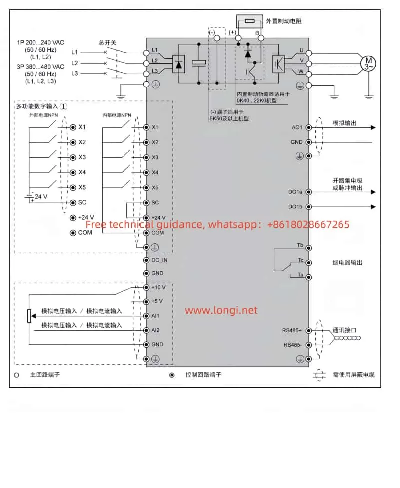
VFC3610_VFC5610 Standard Wiring Diagram

II. External Terminal Control and Speed Adjustment

2.1 External Terminal Forward and Reverse Control

Users can control the forward and reverse operations of the frequency converter through external terminals. The steps are as follows:

  1. Set parameter [E0.17] = ‘0: Forward / Reverse’.
  2. Connect the terminals:
  • X1: Multifunctional digital input for forward control.
  • X2: Multifunctional digital input for reverse control.

2.2 External Potentiometer Speed Adjustment

Users can adjust the speed of the frequency converter using an external potentiometer. The steps are as follows:

  1. Set parameter [E0.00] = ‘2: Al1 Analog Input’.
  2. Connect the terminals:
  • Al1: Analog voltage input for frequency setting.
  • GND: Common ground for analog input.

III. Fault Codes and Handling

3.1 Fault Codes

The Bosch Rexroth VFC3610/VFC5610 series provides detailed fault codes to help users quickly identify and resolve issues. Some common fault codes and their meanings are as follows:

  • 0: No fault
  • 1: OC-1, Overcurrent during constant speed
  • 2: OC-2, Overcurrent during acceleration
  • 3: OC-3, Overcurrent during deceleration
  • 4: OE-1, Overvoltage during constant speed
  • 5: OE-2, Overvoltage during acceleration
  • 6: OE-3, Overvoltage during deceleration
  • 7: OE-4, Overvoltage during stop
  • 8: UE-1, Undervoltage during operation
  • 9: SC, Current surge or short circuit
  • 10: IPH.L, Input phase loss
  • 11: OPH.L, Output phase loss
  • 12: ESS-, Soft start fault
  • 20: OL-1, Overload
  • 21: OH, Overheating
  • 23: FF, Fan failure
  • 24: Pdr, No-load protection
  • 25: Col:, Command value loss

3.2 Fault Handling

When a fault occurs, users should take appropriate actions based on the fault code’s meaning. For example:

  • Overcurrent Faults (1, 2, 3): Check if the motor and load are functioning correctly. Ensure proper cable connections and adjust parameter settings if necessary.
  • Overvoltage Faults (4, 5, 6, 7): Check if the power supply voltage is stable. Ensure proper cable connections and adjust parameter settings if necessary.
  • Undervoltage Fault (8): Check if the power supply voltage is normal. Ensure proper cable connections.
  • Short Circuit Fault (9): Check cable and terminal connections for short circuits.
  • Phase Loss Faults (10, 11): Check cable and terminal connections for phase loss.
  • Overload Fault (20): Check if the motor and load are functioning correctly. Ensure proper cable connections and adjust parameter settings if necessary.
  • Overheating Fault (21): Check the cooling conditions of the frequency converter. Ensure the fan is working properly and clean the heat sink if necessary.
  • Fan Failure (23): Check if the fan is working properly. Replace the fan if necessary.
  • No-load Protection (24): Check if the motor is running correctly and ensure the load is normal.
  • Command Value Loss (25): Check communication cables and terminals for proper connections. Ensure communication is functioning correctly.

Conclusion

The Bosch Rexroth VFC3610/VFC5610 series frequency converters are powerful and user-friendly devices suitable for various industrial control applications. This guide provides a comprehensive overview of the operating panel functions, parameter settings, and fault handling for these frequency converters. By following this guide, users can effectively operate and maintain these devices, enhancing productivity and reliability.

Posted on

CONVO Variable Frequency Drive G3/P3 Series User Manual Guide

The CONVO Variable Frequency Drive G3/P3 Series is a high-performance variable speed control device widely used in industrial automation, fans, pumps, and other fields. This article provides a detailed guide on the operation panel functions, parameter initialization, parameter copying, password setting and removal, parameter access restrictions, external terminal control, fault codes, and troubleshooting for the CONVO Variable Frequency Drive G3/P3 Series.

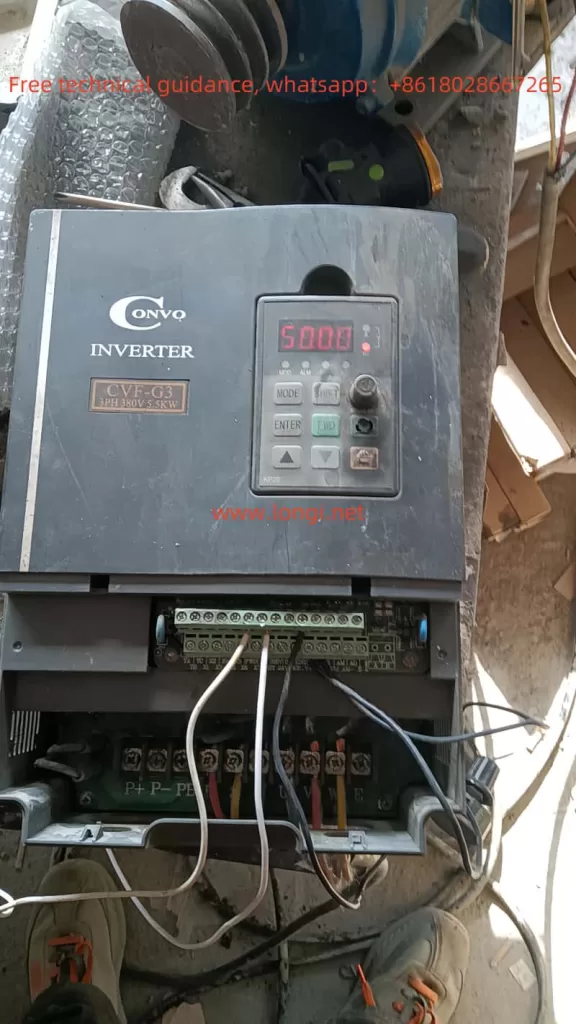
CVF-G3 physical working diagram

I. Introduction to Operation Panel Functions

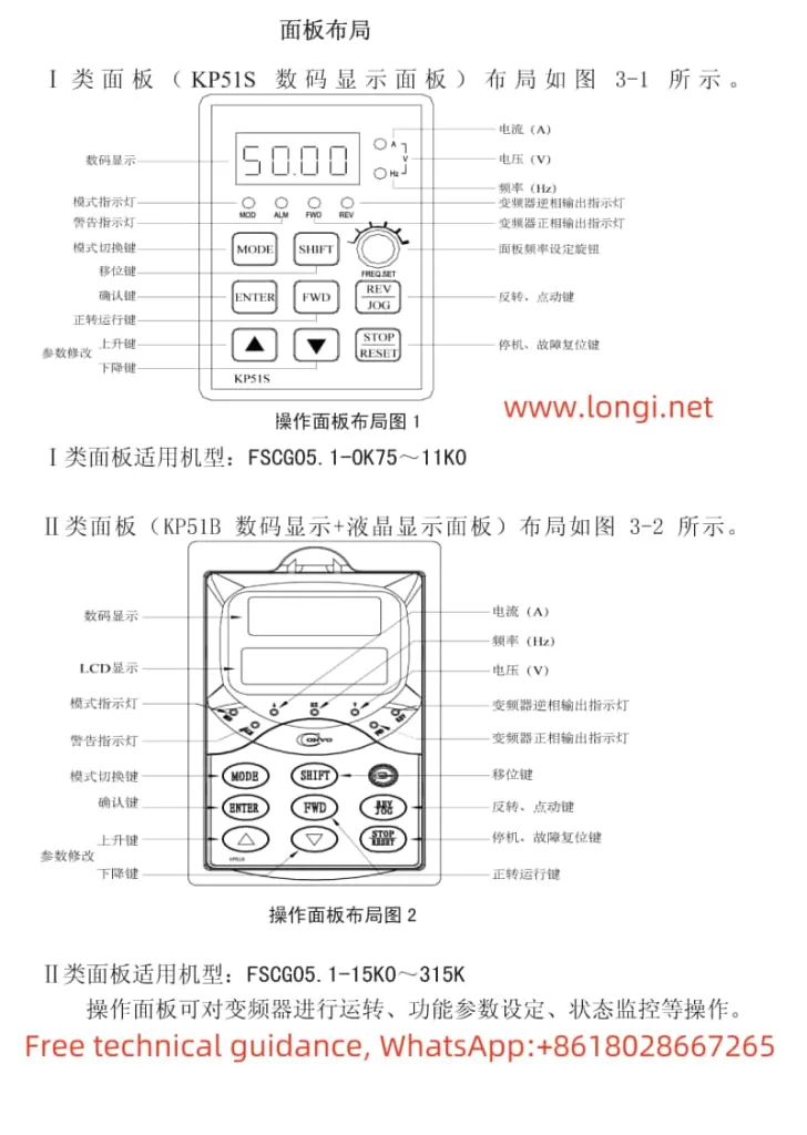
The operation panel of the CONVO Variable Frequency Drive G3/P3 Series integrates multiple functions, including operation control, parameter settings, and status monitoring. The main function keys and their uses are as follows:

  1. RUN (Run): Starts the frequency drive.
  2. LOCAL/REMOT (Local/Remote): Switches between local control and remote control modes.
  3. FWD/REV (Forward/Reverse): Sets the running direction of the motor.
  4. TUNE/TC (Tune/Speed Adjustment): Enters the tuning or speed adjustment mode.
  5. PRG (Program): Enters the program setting mode.
  6. QUICK (Quick): Quickly sets the frequency.
  7. MF.K (Multifunction Key): Multifunction button used for operations in different modes.
  8. STOP/RST (Stop/Reset): Stops the frequency drive operation or resets the system.
  9. ENTER (Confirm): Confirms the current operation.
  10. ↑ (Up) and ↓ (Down): Adjusts parameter values or frequency.

Through these buttons, users can easily control the operation status of the frequency drive, set parameters, and monitor the system status.

II. Parameter Initialization (Restore Factory Settings)

Parameter initialization refers to restoring all parameters of the frequency drive to their factory settings. The specific operation steps are as follows:

  1. Enter the parameter setting mode: Press the PRG key to enter the parameter setting mode.
  2. Select parameter initialization: Use the or keys to select the parameter H-73 (Parameter Initialization).
  3. Set the initialization value: Set the value of H-73 to 1 (Restore factory settings by machine type) or 2 (Clear fault records).
  4. Confirm the operation: Press the ENTER key to confirm, and the frequency drive will automatically restore to the factory settings.

III. Using the Operation Panel to Copy Parameters to Another Frequency Drive of the Same Model

The parameter copying function allows users to copy the parameter settings from one frequency drive to another frequency drive of the same model. The specific operation steps are as follows:

  1. Prepare two frequency drives of the same model and ensure they are in the same initial state.
  2. On the source frequency drive, enter the parameter setting mode, select the parameter H-73, and set it to 3 (Parameter Copy).
  3. Use a communication cable to connect the RS485 interfaces of the two frequency drives.
  4. On the target frequency drive, enter the parameter setting mode, select the parameter H-73, and set it to 4 (Receive Parameters).
  5. Press the ENTER key, and the source frequency drive will transmit all parameters to the target frequency drive.
  6. After completion, disconnect the communication cable, and the parameter settings of the two frequency drives will be consistent.
G3-P3 series standard wiring diagram

IV. Setting and Removing Passwords

The CONVO Variable Frequency Drive G3/P3 Series supports setting passwords to protect parameter settings. The specific operation steps are as follows:

Setting a Password

  1. Enter the parameter setting mode: Press the PRG key to enter the parameter setting mode.
  2. Select password setting: Use the or keys to select the parameter H-79 (Password Setting).
  3. Enter the password: Press the ENTER key, enter a 4-digit numeric password, and then press the ENTER key to confirm.

Removing a Password

  1. Enter the parameter setting mode: Press the PRG key to enter the parameter setting mode.
  2. Select password setting: Use the or keys to select the parameter H-79 (Password Setting).
  3. Enter the current password: Press the ENTER key, enter the current password, and then press the ENTER key to confirm.
  4. Clear the password: Set the password to 0000, and then press the ENTER key to confirm.

V. Setting Parameter Access Restrictions

To prevent parameters from being accidentally modified, the CONVO Variable Frequency Drive G3/P3 Series provides a parameter access restriction function. The specific operation steps are as follows:

  1. Enter the parameter setting mode: Press the PRG key to enter the parameter setting mode.
  2. Select parameter access restriction: Use the or keys to select the parameter L-72 (Parameter Write Protection).
  3. Set access restriction: Set the value of L-72 to 1 (Prohibit modifying other parameters except for the digital set frequency and this parameter) or 2 (Prohibit modifying all parameters except for this parameter).
  4. Confirm the operation: Press the ENTER key to confirm.

VI. External Terminal Forward/Reverse Start/Stop and External Potentiometer Speed Control

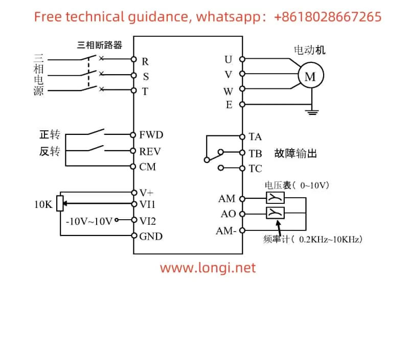
The CONVO Variable Frequency Drive G3/P3 Series supports external terminal control for forward/reverse start/stop and external potentiometer speed control. The specific wiring and parameter settings are as follows:

External Terminal Forward/Reverse Start/Stop

  1. Wiring:
  • FWD (Forward): Connect to the external forward control terminal.
  • REV (Reverse): Connect to the external reverse control terminal.
  • CM (Common): Connect to the common terminal of the external control terminal.
  1. Parameter Settings:
  • b-3 (Run Command Channel Selection): Set to 1 (External Terminal Control).
  • b-4 (Direction Control): Set to 0 (Consistent with Set Direction) or 1 (Opposite to Set Direction).

External Potentiometer Speed Control

  1. Wiring:
  • VI1 (External Voltage Input 1): Connect to the output terminal of the external potentiometer.
  1. Parameter Settings:
  • b-1 (Frequency Input Channel Selection): Set to 2 (External Voltage Signal 1).
  • L-34 (VI1 Input Lower Limit Voltage): Set to the minimum output voltage of the external potentiometer.
  • L-35 (VI1 Input Upper Limit Voltage): Set to the maximum output voltage of the external potentiometer.
  • L-36 (VI1 Input Adjustment Coefficient): Set to an appropriate adjustment coefficient to match the output range of the potentiometer.

VII. Fault Codes and Troubleshooting

The CONVO Variable Frequency Drive G3/P3 Series provides detailed fault codes to help users quickly identify and resolve issues. The following are common fault codes and their troubleshooting methods:

  1. E01: Overcurrent Fault
  • Meaning: The output current of the frequency drive exceeds the set value.
  • Troubleshooting: Check if the load is too large, and ensure that the rated current of the frequency drive matches the load.
  1. E02: Overvoltage Fault
  • Meaning: The input voltage of the frequency drive exceeds the set value.
  • Troubleshooting: Check if the input voltage is stable, and ensure that the power supply voltage is within the allowed range of the frequency drive.
  1. E03: Undervoltage Fault
  • Meaning: The input voltage of the frequency drive is below the set value.
  • Troubleshooting: Check if the power supply voltage is stable, and ensure that the power supply voltage is within the allowed range of the frequency drive.
  1. E04: Overheating Fault
  • Meaning: The internal temperature of the frequency drive exceeds the set value.
  • Troubleshooting: Check the heat dissipation conditions, and ensure that there is sufficient airflow around the frequency drive.
  1. E05: Overload Fault
  • Meaning: The output current of the frequency drive exceeds the set value for a long time.
  • Troubleshooting: Check if the load is too large, and ensure that the rated current of the frequency drive matches the load.
  1. E06: Motor Overload
  • Meaning: The motor overload protection is activated.
  • Troubleshooting: Check if the motor is overloaded, and ensure that the rated current of the motor matches the frequency drive.
  1. E07: Motor Overheating
  • Meaning: The motor temperature exceeds the set value.
  • Troubleshooting: Check the heat dissipation conditions of the motor, and ensure that there is sufficient airflow around the motor.
  1. E08: Motor Stall
  • Meaning: The motor stall protection is activated.
  • Troubleshooting: Check if the motor is stalled, and ensure that the operating environment of the motor is normal.
  1. E09: Motor Phase Loss
  • Meaning: The motor phase loss protection is activated.
  • Troubleshooting: Check if the motor wiring is correct, and ensure that the three-phase power supply of the motor is normal.
  1. E10: Motor Phase Sequence Error
    • Meaning: The motor phase sequence error protection is activated.
    • Troubleshooting: Check if the motor wiring is correct, and ensure that the phase sequence of the motor is correct.

Conclusion

The CONVO Variable Frequency Drive G3/P3 Series is a powerful and easy-to-operate variable speed control device. Through this detailed introduction, users can master the operation panel functions, parameter initialization, parameter copying, password setting and removal, parameter access restrictions, external terminal control, fault codes, and troubleshooting methods of the frequency drive. It is hoped that this article will help users better utilize the CONVO Variable Frequency Drive G3/P3 Series, improving work efficiency and the reliability of the equipment.

Posted on

User Manual Guide for Convo Inverter FSCG05 Series

I. Introduction to Operating Panel Functions and Initialization Settings

1. Operating Panel Function Introduction

The Convo FSCG05 series inverters come equipped with an intuitive operating panel that offers extensive functionalities for parameter setting, monitoring, and control.

2. Factory Default Initialization Settings
Function diagram of CONVO inverter CVF-G5 panel

To restore the inverter to its factory default settings, you need to modify specific parameters. The key parameter to be set is b-11 (Parameter Initialization). Here’s how to do it:

  • Parameter and Settingb-11 = 1
  • Procedure:
    1. Access the advanced parameter mode by setting b-0 = 2.
    2. Navigate to b-11 and set its value to 1.
    3. Save the setting and restart the inverter to apply the factory defaults.
3. Copying and Downloading Parameters via Operating Panel

Copying Parameters:

  • Procedure for KP51B Keypad:
    1. Set the source inverter to parameter copy mode by pressing EnterStopDownEnter sequentially.
    2. Remove the keypad from the source inverter and insert it into the target inverter.
    3. Initiate the parameter download to the target inverter by pressing EnterStopDownDown sequentially.
  • Procedure for KP51S Keypad (due to limited memory, parameters need to be copied in two batches):
    • For copying B and L parameters: Press EnterStopDownDownEnter.
    • For copying H and E parameters: Press EnterStopDownStopDown.
    • To copy all B, L, H, and E parameters, follow the above steps for each batch.

Downloading Parameters:

  • Simply reverse the above steps to download parameters from the keypad to an inverter.

II. Terminal Control for Forward/Reverse Rotation and Potentiometer Speed Regulation

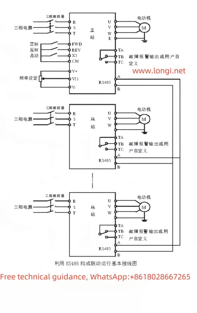
CONVO frequency converter SCG05 multi machine RS485 communication synchronization function diagram
Setting Parameters for Terminal Control
  • Forward/Reverse Rotation Control:
    • Set b-3 to select the control mode (e.g., 1 for external terminal control with keyboard stop disabled).
    • Configure the function of terminals X1, X2, FWD, and REV via parameters like L-47 to L-53 based on your control requirements.
  • Potentiometer Speed Regulation:
    • Set b-1 to 0 to use the potentiometer on the operating panel for speed control.
    • No additional parameter settings are required if using the panel potentiometer exclusively.

CONVO is a brand under Bosch Rexroth,By following these steps and adjusting the specified parameters, you can effectively control the operation of your Convo FSCG05 series inverter, whether through the operating panel, external terminals, or by restoring factory settings. This user manual guide aims to provide a comprehensive reference for smooth and efficient inverter operation.