Abstract
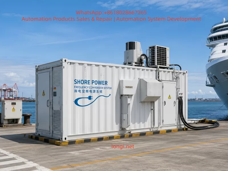
Shore power frequency conversion systems are used to convert utility power supplied by a port into stable electrical power that meets the voltage, frequency, grounding, and power-quality requirements of a vessel. Because shore-side and shipboard electrical systems may operate at different voltage and frequency standards, large shore power installations commonly adopt a combination of input transformer, static frequency converter, output transformer, switching equipment, and supervisory control.
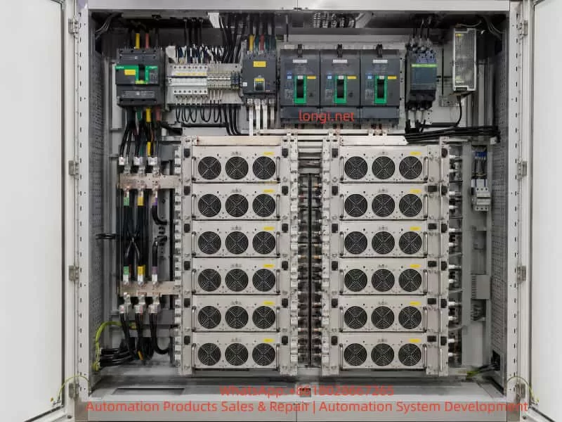
This article examines a 630 kVA shore power frequency conversion system rated for 380 V, 50 Hz input and 440 V, 60 Hz output. The system contains two parallel 400 kVA converter units, each built from eight parallel power modules. During startup, all inverter modules simultaneously reported:
- 05E-07: Abnormal DC component in inverter voltage
- 05A-02: Inverter self-test error
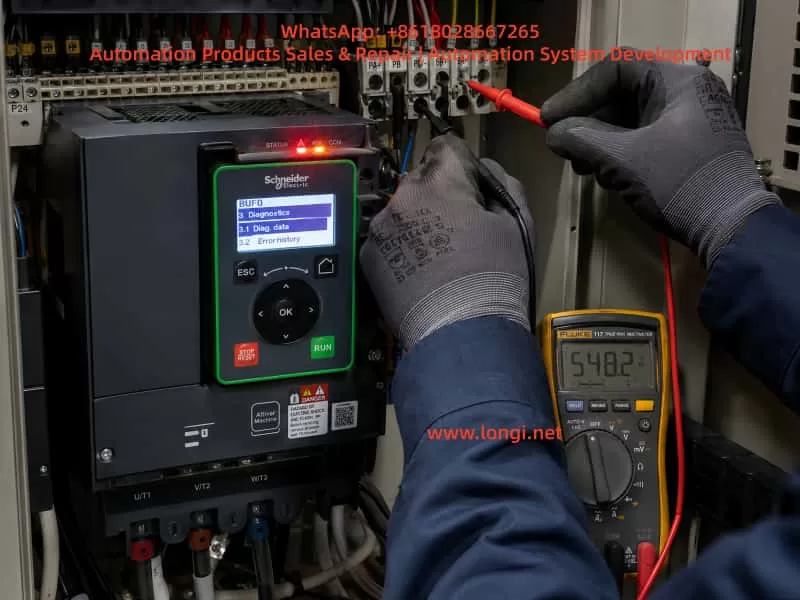
The inverter output remained at approximately 164 V and 31.9 Hz during the no-load self-test stage. A handheld multimeter also indicated approximately 90 VDC between each output phase and neutral, leading initially to suspicion of a PFC, DC-bus, voltage-sensing, or common control fault.
Further investigation showed that the real cause was much more specific. Inside one power module, a high-voltage conductor had damaged insulation and was touching or leaking through the fan frame and protective-earth path. The resistance between the conductor and ground was only about 300 Ω, whereas the corresponding point in a healthy module was effectively open circuit. The fault pulled a normally higher-voltage node down from approximately 250 V to slightly above 100 V and contaminated an isolated auxiliary supply of about 14 V with a common-mode voltage of several hundred volts.
Because corresponding auxiliary and control circuits were interconnected across the eight parallel modules, the abnormal common-mode potential affected the inverter gate-drive and voltage-detection references of the entire converter. This caused all modules to report the same inverter DC-component fault. After the damaged conductor was insulated and mechanically repositioned, the module and complete converter returned to normal operation.
The case demonstrates that a system-level inverter failure does not necessarily originate from failed IGBTs, a defective PFC stage, or a faulty master controller. High-voltage wiring, fan assemblies, auxiliary power supplies, grounding paths, mechanical abrasion, and common-mode coupling can produce the same alarm pattern and must be included in the diagnostic process.
Keywords: shore power converter, modular UPS, PFC boost stage, three-level inverter, inverter DC offset, auxiliary power supply, insulation failure, earth leakage, parallel power module, high-voltage wiring
1. Why a Shore Power System Cannot Be Treated as an Ordinary Variable-Frequency Drive
The basic purpose of shore power is to supply a vessel from the port electrical grid while the vessel is berthed. This allows onboard diesel generators to be shut down or operated at reduced output, decreasing fuel consumption, exhaust emissions, noise, and vibration.
However, shore power is not simply a matter of connecting a three-phase cable from the port to the vessel. Shore-side and shipboard distribution systems may differ in several important ways.
A port electrical network may provide:
- 380 V, 50 Hz;
- 400 V, 50 Hz;
- three-phase four-wire power;
- a neutral directly associated with the shore grounding system.
A vessel may require:
- 440 V, 60 Hz;
- 450 V, 60 Hz;
- 460 V, 60 Hz;
- 480 V, 60 Hz;
- three-phase three-wire power;
- a different grounding or neutral arrangement.
The vessel may also contain a large number of motors, pumps, compressors, air-conditioning systems, galley loads, navigation equipment, control systems, and nonlinear rectifier loads. These loads may require tighter limits on voltage, frequency, harmonic distortion, grounding, and electrical isolation than ordinary industrial loads.
A transformer can change voltage but cannot change frequency. If the shore supply is 50 Hz and the vessel requires 60 Hz, a transformer alone is insufficient. The system must use either a rotating motor-generator set or a static semiconductor frequency converter.
The equipment examined in this case had the following nameplate data:
- System capacity: 630 kVA
- Input: AC 380 V, 50 Hz, 3P+N+PE
- Output: AC 440 V, 60 Hz, 3P+PE
- Input transformer cabinet included
- Output transformer cabinet included
- Two converter sections identified as frequency converter No. 1 and No. 2
The installation was therefore not a conventional motor-drive VFD. It was a complete shore power frequency conversion system consisting of transformers, parallel static converters, switching devices, output distribution, and monitoring equipment.
Its power-conversion hardware was based on a high-power online UPS platform, but in this application it primarily functioned as a static frequency converter rather than as a conventional battery-backed data-center UPS.
2. Overall Power-Conversion Path of the System
Based on the field nameplates, single-line diagrams, switchgear layout, and internal module construction, the system can be represented as follows:
Port utility supply
Three-phase 380 V, 50 Hz
          │
          ▼
Input switchgear and input transformer
          │
          ▼
Two parallel 400 kVA converter units
          │
          ▼
Three-phase active rectifier / PFC stage
          │
          ▼
High-voltage split DC bus
          │
          ▼
Three-phase PWM inverter
          │
          ▼
Output LC filtering
          │
          ▼
Parallel output bus and isolation switches
          │
          ▼
Output transformer
          │
          ▼
Shipboard supply
Three-phase 440 V, 60 Hz
This is an AC-to-DC-to-AC double-conversion system.
The front-end converter rectifies the input and controls the DC bus. The rear inverter reconstructs an output waveform whose voltage and frequency are independent of the input frequency.
This structure provides several advantages:
- 50 Hz input can be converted to 60 Hz output.
- Output voltage can be regulated independently of the utility voltage.
- Input voltage disturbances do not pass directly to the vessel.
- Input power factor can be controlled.
- Input current harmonics can be reduced.
- Multiple modules can operate in parallel.
- Redundancy can be implemented.
- A battery can be connected if backup operation is required.
- A bypass path can be incorporated for maintenance or emergency operation.
In this project, no external battery bank was installed. The “Battery+,” “Battery N,” and “Battery−” terminals remained part of the power-module architecture because the converter hardware was derived from an online UPS platform. The absence of a battery did not prevent normal AC-to-AC operation because the PFC stage established the DC bus directly from the utility input.
3. The Power Module Is a Complete Double-Conversion Converter, Not Merely an Inverter Board
Markings visible on the removed module included designations such as:
YDC3300 MOD5.PCB
The internal construction confirmed that each module contained far more than a single inverter bridge. It was a complete modular power-conversion unit incorporating:
- input protection;
- EMI filtering;
- three-phase PFC;
- high-voltage DC energy storage;
- inverter switching;
- output filtering;
- isolated auxiliary power;
- gate-drive circuitry;
- voltage and current sensing;
- digital control and communication.
A simplified module structure is:
Three-phase AC input
        │
        ▼
Input fuses and EMI filter
        │
        ▼
Three-phase boost inductors
        │
        ▼
Active rectifier / PFC bridge
        │
        ▼
Split DC bus
DC+ — N — DC-
        │
        ▼
Three-phase three-level inverter
        │
        ▼
LC output filter
        │
        ▼
Three-phase AC output
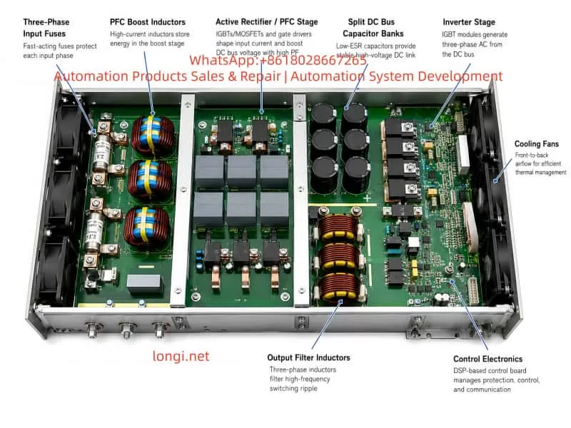
The major physical sections can be identified directly from the photographs.
4. Major Internal Sections of the Module
4.1 Three-Phase Input Fuses
Three large cylindrical fuses were installed in the input section, corresponding to the three input phases.
Their functions include:
- isolating an internal module short circuit;
- protecting the PFC switching devices;
- preventing a failed module from damaging the common input bus;
- limiting fault energy during semiconductor failure;
- allowing each power module to be serviced independently.
In a parallel modular system, individual input protection is essential. Without it, a short circuit inside one module could collapse the input supply for all remaining modules.
4.2 PFC Boost Inductors
The module contained several large copper-wound magnetic components. The three inductors closest to the input section were consistent with three-phase PFC boost inductors.
These components were not line-frequency transformers. They functioned as energy-storage inductors in a high-frequency switched power stage.
Their roles included:
- storing energy during each switching cycle;
- supporting DC-bus voltage boost;
- shaping the input current;
- reducing current ripple;
- helping maintain a high input power factor;
- limiting current change during transient conditions.
A high-power three-phase PFC may use a Vienna rectifier, a three-level active rectifier, or another boost-type PWM rectifier topology. Regardless of the exact topology, the control system monitors input voltage, input current, and DC-bus voltage, then adjusts switching duty cycles to regulate both the DC bus and the shape of the input current.
4.3 Split DC-Bus Capacitor Banks
Large numbers of high-voltage electrolytic capacitors were arranged around the power section.
The external terminals were marked:
Battery+
Battery N
Battery-
This strongly indicated a split DC-bus structure:
DC+
 │
Upper DC-bus capacitor bank
 │
DC midpoint N
 │
Lower DC-bus capacitor bank
 │
DC-
When a battery system is installed, the positive terminal, midpoint, and negative terminal of the battery bank can be connected to these bus points.
When no battery is installed, the active rectifier still charges and regulates the upper and lower DC-bus capacitor banks.
A split DC bus is especially suitable for three-level rectifier and inverter circuits. Instead of switching only between DC+ and DC−, the inverter can also use the midpoint potential. This reduces voltage stress on individual power semiconductors and decreases the voltage step applied to the output filter.
4.4 PFC Power Semiconductors
Under the large aluminum heatsinks were likely combinations of:
- IGBTs;
- power MOSFETs;
- fast-recovery diodes;
- silicon-carbide diodes;
- clamping devices;
- current-sensing elements;
- snubber components.
The PFC controller uses measured three-phase voltage and current signals to generate switching commands. The purpose is not merely to rectify the input, but also to regulate the positive and negative DC buses and keep their midpoint balanced.
4.5 Three-Phase Inverter Bridge
The power devices closer to the output section formed the inverter stage.
The module architecture and three-terminal DC bus were consistent with a three-level inverter. A three-level circuit offers several advantages over a basic two-level inverter:
- lower voltage stress per switching device;
- smaller output voltage steps;
- reduced high-frequency harmonic content;
- potentially lower switching loss;
- easier output filtering;
- better suitability for large modular UPS and static frequency-converter applications.
Each phase leg switches among the positive bus, midpoint, and negative bus. The three phases are modulated 120 electrical degrees apart to synthesize a balanced three-phase output.
4.6 Output Inductors and Filter Capacitors
The inverter bridge does not directly produce a clean sine wave. Its raw output is a high-frequency PWM waveform.
The module therefore contains output magnetic components and capacitors forming a filter network. These may include:
- differential-mode inductors;
- common-mode inductors;
- phase filter capacitors;
- neutral-point capacitors;
- damping resistors or damping networks.
The filter attenuates the high-frequency switching component while preserving the required 50 Hz or 60 Hz fundamental.
4.7 Isolated Auxiliary Supplies and Gate Drivers
A large power converter contains many isolated auxiliary supplies.
Typical rails may include:
- +15 V;
- −5 V for negative gate turn-off;
- +12 V or +14 V;
- +5 V;
- +3.3 V;
- 24 V control supply.
The high-side, low-side, and midpoint switching devices operate at different high-voltage potentials. Each gate-driver circuit must therefore be powered by an isolated supply referenced to the local emitter or source of its corresponding switching device.
This detail became central to the fault.
An isolated 14 V supply can be perfectly normal when measured between its local positive and local negative terminals, while the entire isolated circuit may float hundreds of volts above protective earth.
The correct interpretation depends entirely on the measurement reference.
5. How a 380 V Input Can Produce a 440 V Output
A common question is:
If the input is only 380 V and there is no large step-up transformer inside each power module, how can the system produce 440 V?
The answer involves three separate stages:
- PFC raises and regulates the DC-bus voltage.
- The inverter reconstructs controlled AC from the elevated DC bus.
- The system output transformer performs final voltage matching and isolation.
5.1 Natural DC Voltage from Three-Phase Rectification
For a three-phase 380 V line-to-line input, the line-voltage peak is:
[
V_{\text{peak}}=380\sqrt{2}\approx537\text{ V}
]
The average DC voltage from a conventional six-pulse diode bridge is approximately:
[
V_{DC}\approx1.35V_{LL}
]
Therefore:
[
V_{DC}\approx1.35\times380\approx513\text{ V}
]
Without active boosting, the DC bus would normally remain in the range of approximately 510 to 540 V, depending on load, line voltage, and rectifier configuration.
5.2 Why a 500 V DC Bus May Not Be Sufficient
The maximum AC voltage that an inverter can synthesize is limited by its DC-bus voltage.
For a three-phase inverter using space-vector modulation, the theoretical maximum line-to-line RMS voltage is approximately:
[
V_{LL,\max}\approx\frac{V_{DC}}{\sqrt{2}}
]
To produce 440 V line-to-line directly, the theoretical minimum DC bus is therefore approximately:
[
V_{DC}\approx440\sqrt{2}\approx622\text{ V}
]
This figure does not include practical design margin.
A real system must also compensate for:
- semiconductor voltage drop;
- DC-bus ripple;
- output-filter voltage drop;
- input-voltage variation;
- load transients;
- modulation margin;
- overload requirements;
- harmonic-performance requirements.
Consequently, if the inverter itself must directly generate 440 V, the DC bus will normally be regulated above the theoretical minimum, potentially in the range of approximately 650 to 800 V depending on the exact circuit.
5.3 How the PFC Inductor Produces Voltage Boost
The PFC stage uses the same fundamental principle as a boost converter.
When a switching device turns on, current increases through the input inductor and energy is stored in its magnetic field:
[
E=\frac{1}{2}LI^2
]
When the switch turns off, the inductor current cannot stop instantly. The inductor generates a voltage that maintains current flow. This induced voltage adds to the rectified input voltage and transfers energy into the DC-bus capacitors.
The process can be represented as:
Switch ON
Input source → inductor stores energy

Switch OFF
Input source + inductor discharge voltage
                     ↓
          charges the DC-bus capacitors
For an ideal boost converter:
[
V_{out}=\frac{V_{in}}{1-D}
]
where (D) is the switching duty ratio.
As duty ratio increases, the theoretical output voltage rises. However, this equation is only an idealized model. A real industrial converter cannot increase voltage indefinitely.
The maximum usable DC-bus voltage is limited by:
- IGBT or MOSFET voltage rating;
- diode reverse-voltage rating;
- capacitor voltage rating;
- busbar insulation;
- PCB creepage and clearance;
- gate-drive isolation;
- voltage-sensor range;
- software overvoltage threshold;
- inductor saturation;
- switching loss;
- thermal performance;
- transient voltage overshoot.
For this type of 380/400 V three-phase modular converter, an engineering estimate for the normal total split-bus voltage is approximately 650 to 800 V, with each half bus approximately 325 to 400 V relative to the midpoint.
The actual target must be confirmed from the service manual, internal measurement menu, or comparison with the healthy No. 2 converter.
5.4 The Role of the Output Transformer
The field nameplate and system diagrams confirmed that an output transformer cabinet was part of the installation.
Therefore, the power modules did not necessarily have to generate the final 440 V directly.
A likely arrangement was:
Converter output
Approximately 380 or 400 V, 60 Hz
             │
             ▼
Output isolation transformer
             │
             ▼
Shipboard output
440 V, 60 Hz
If the inverter common bus produced 400 V, the required transformer ratio would be:
[
\frac{440}{400}=1.10
]
If the inverter produced 380 V, the ratio would be:
[
\frac{440}{380}\approx1.158
]
The output transformer could also perform several additional functions:
- shore-to-ship galvanic isolation;
- grounding-system conversion;
- three-phase four-wire to three-phase three-wire conversion;
- common-mode current limitation;
- switching-noise suppression;
- fault-protection coordination.
The system nameplate stated:
- Input: 3P+N+PE
- Output: 3P+PE
The absence of an output neutral supports the conclusion that the output transformer was also used to create the required three-wire shipboard system.
6. Fault Symptoms Observed in the Field
The system contained two parallel converter units. Converter No. 2 operated normally. Converter No. 1 failed during inverter startup.
Each converter contained eight parallel power modules.
The faulty converter reported:
- 05E-07: Abnormal DC component in inverter voltage
- 05A-02: Inverter self-test error
The alarms were associated with:
- INV01
- INV02
- INV03
- INV04
- INV05
- INV06
- INV07
- INV08
All eight modules reported almost the same fault within approximately one or two seconds.
The input readings were normal:
- line voltage approximately 396 to 402 V;
- frequency 50 Hz;
- balanced three-phase voltage;
- only several amperes of standby or self-test current.
During the failed no-load inverter self-test, the display showed:
- output line voltage approximately 163 to 165 V;
- output phase voltage approximately 94 to 95 V;
- frequency 31.9 Hz;
- output current 0 A;
- output power 0 kW.
The relationship between phase voltage and line voltage was correct:
[
95\sqrt{3}\approx164.5\text{ V}
]
This indicated that the inverter had already begun generating a balanced low-voltage, low-frequency three-phase waveform. It failed before reaching rated voltage and frequency.
7. Why the Fault Was Initially Suspected to Be Related to PFC, the DC Bus, or Voltage Sensing
When eight modules report the same inverter fault simultaneously, it is reasonable to suspect a shared condition.
Initial candidates included:
- PFC stage;
- DC-bus imbalance;
- common output-voltage sensing;
- neutral reference;
- master inverter controller;
- PWM synchronization;
- shared auxiliary supply;
- shared communication or current-sharing signals.
This diagnostic direction was logical, even though the final root cause was different.
7.1 The Input Side Appeared Normal
The input voltage and frequency were stable, and the system event log indicated:
- rectifier supplied by input source;
- PFC active.
There were no clear alarms for:
- rectifier failure;
- DC-bus overvoltage;
- DC-bus undervoltage;
- input phase loss;
- severe input imbalance;
- failure to establish the DC bus.
This made a major PFC-stage failure less likely.
7.2 The Three-Phase Output RMS Values Were Balanced
A severe failure of one inverter phase would commonly produce:
- one phase significantly low or high;
- major voltage imbalance;
- overcurrent;
- fuse operation;
- a phase-leg or driver fault specific to one module.
Instead, the three output RMS values were closely matched.
7.3 All Eight Modules Reported the Same Alarm
The probability that all eight power modules independently developed the same semiconductor failure at the same time was extremely low.
A more plausible explanation was:
- one common signal affected every module;
- one defective module contaminated a shared circuit;
- a shared auxiliary supply became unstable;
- a common reference was shifted;
- a high-voltage fault propagated through the parallel architecture.
The final diagnosis confirmed that a single module had contaminated an interconnected auxiliary/control reference.
8. Why a 90 VDC Reading on a Multimeter Did Not Directly Prove a 90 V DC Offset
A handheld digital multimeter in DC mode indicated approximately 90 V between each output phase and neutral.
Similar readings were present even before the inverter had fully started.
This result was important but could not be treated as direct proof of a true 90 V average DC component.
8.1 The Output Was Not an Ideal Sine-Wave Source
A PWM inverter output may contain:
- the low-frequency AC fundamental;
- high-frequency switching residue;
- common-mode voltage;
- parasitic capacitive current;
- EMI-filter charging current;
- a floating neutral potential;
- switching spikes.
A general-purpose multimeter has limited bandwidth and uses an internal measurement algorithm that may not accurately separate true DC average value from high-frequency common-mode content.
8.2 High-Impedance Meters Read Ghost Voltage
Digital multimeters commonly have input impedances of several megohms.
A very small leakage path through:
- Y capacitors;
- snubber capacitors;
- voltage-sensing resistor networks;
- EMI filters;
- parasitic capacitance;
can therefore produce a reading of tens or hundreds of volts without having meaningful current-delivery capability.
8.3 Input and Output Shared the Neutral
The site confirmed that input and output used a common neutral connection.
Because the power modules contained many capacitive and sensing paths to the midpoint, PE, and DC bus, the phase-to-neutral DC-mode reading could be influenced by several internal networks simultaneously.
8.4 Correct Measurement of Real DC Offset
A true inverter-output DC offset should be evaluated using:
- a power-quality analyzer with known low-pass characteristics;
- an isolated high-voltage differential probe;
- oscilloscope averaging over multiple cycles;
- a suitable external low-pass filter;
- the converter’s internal DSP DC-offset value;
- comparison with the healthy converter under identical conditions.
A conventional grounded oscilloscope probe must never be connected directly to a high-power inverter output unless the measurement arrangement is specifically designed for that voltage and isolation requirement.
The 90 V multimeter reading was therefore a diagnostic clue, not a standalone conclusion.
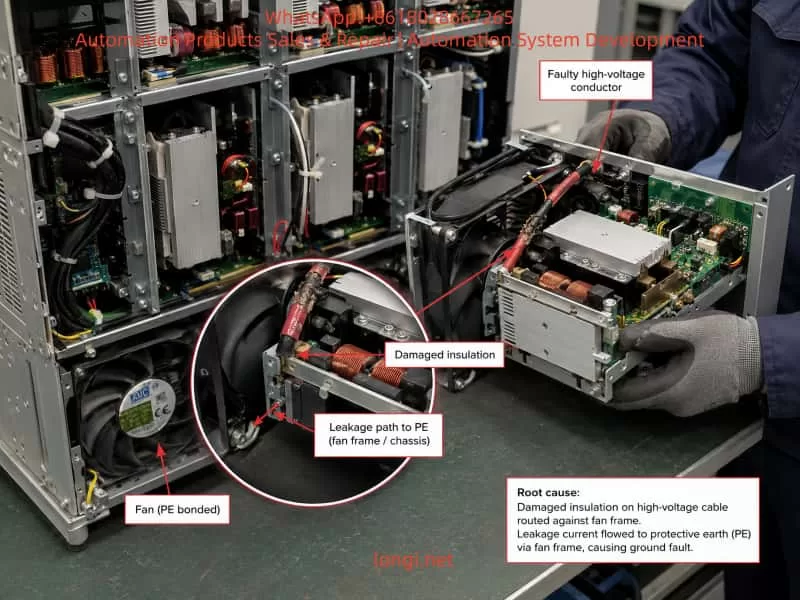
9. The Actual Root Cause: High-Voltage Wire Insulation Failure and Leakage to the Fan Grounding Structure
The faulty module was removed and inspected.
A high-voltage conductor had damaged insulation and was in contact with, or leaking through, the metal fan structure and protective-earth path.
The observations were:
- the corresponding high-voltage node was normally around 250 V;
- during the fault, it measured only slightly above 100 V;
- resistance between the conductor and the fan/ground path was approximately 300 Ω;
- the corresponding point in a healthy module measured open circuit or effectively infinite resistance;
- the insulation showed evidence of mechanical damage, abrasion, compression, or deterioration.
This was not a harmless ghost-voltage effect. It was a real conductive leakage path.
For a simplified 250 V source and 300 Ω leakage resistance:
[
I=\frac{V}{R}
]
[
I=\frac{250}{300}\approx0.83\text{ A}
]
The actual current depended on the surrounding circuit, semiconductor state, inductance, and switching condition, but 300 Ω was clearly low enough to disturb a high-voltage power stage.
10. How the High-Voltage Leakage Contaminated the 14 V Auxiliary Supply
The investigation also found that a supply normally around 14 V appeared to be at more than 350 V relative to a particular reference.
This required careful interpretation.
10.1 Differential Overvoltage Versus Common-Mode Elevation
There are two very different possibilities.
Case A: 350 V Between the 14 V Positive and Negative Terminals
If the actual voltage across the low-voltage supply were 350 V, the gate-driver ICs, optocouplers, regulators, logic circuits, and associated components would normally be destroyed.
Case B: The Supply Remained 14 V Differentially but Floated at 350 V Relative to PE
This was much more consistent with the field observations.
For example:
14 V+ to 14 V− ≈ 14 V

14 V− to PE ≈ 336 V

14 V+ to PE ≈ 350 V
The supply itself still delivered 14 V to its local circuit, but the entire isolated supply and driver reference had been lifted to a common-mode potential of several hundred volts relative to protective earth.
Floating gate-driver supplies are normal in inverter design. A high-side driver must move with the emitter potential of the corresponding switching device.
However, this floating condition must occur through intentionally designed isolation. In this fault, the common-mode voltage entered through damaged insulation and an unintended ground-leakage path.
The consequences could include:
- uncontrolled common-mode shift of the gate-driver supply;
- excessive stress on driver isolation;
- gate turn-on and turn-off reference errors;
- DESAT protection malfunction;
- output-voltage sensing offset;
- DSP analog-input interference;
- current through communication grounds;
- contamination of parallel auxiliary-power connections;
- false or real inverter DC-offset detection.
11. Why One Defective Module Caused All Eight Modules to Alarm
Parallel modular systems are not eight completely independent converters.
The modules may share or interconnect:
- input busbars;
- output busbars;
- output neutral;
- battery positive, midpoint, and negative buses;
- enable and emergency-stop signals;
- phase synchronization;
- current-sharing signals;
- communication buses;
- portions of auxiliary power;
- control references;
- cable shields.
A fault contained entirely within one isolated module may cause that module alone to shut down.
In this case, the high-voltage leakage affected an auxiliary or control reference that was connected to corresponding circuits in the other modules.
The fault propagation can be represented as:
High-voltage wire insulation failure
                │
                ▼
Leakage through fan frame and PE
                │
                ▼
Isolated auxiliary-supply reference shifted
                │
                ▼
Shared or paralleled 14 V control supply contaminated
                │
                ▼
Gate-drive and voltage-sensing references disturbed
                │
                ▼
Inverter PWM symmetry or detection offset affected
                │
                ▼
Abnormal DC-component alarm in every module
                │
                ▼
System-wide inverter self-test failure
The faulty module did not necessarily apply 350 V differentially across all low-voltage circuits. It more likely introduced an abnormal common-mode potential and leakage current that destabilized the shared reference system.
This explained the complete set of field observations:
- PFC could still activate.
- Input voltage remained normal.
- The inverter could generate a balanced low-voltage waveform.
- The self-test stopped at approximately 31.9 Hz.
- All eight modules reported the same alarm.
- Removal and repair of one module restored the full converter.
12. Why the 250 V Node Was Pulled Down to Slightly Above 100 V
The damaged high-voltage node normally measured around 250 V but fell to slightly above 100 V during the fault.
This behavior is consistent with a leakage-loaded high-impedance node.
A simplified equivalent circuit is:
High-voltage source
        │
Internal source impedance
        │
Measured node
        │
Damaged insulation resistance
        │
Protective earth
Before insulation failure, the node was effectively isolated from PE.
After the approximately 300 Ω leakage path appeared, the node voltage was determined by a divider formed by:
- the internal source impedance;
- switching-device state;
- inductor resistance;
- precharge and balancing resistors;
- capacitor charge;
- paths through other connected modules.
The voltage being pulled from 250 V to approximately 100 V did not indicate that the PFC had lost its ability to boost the DC bus. It showed that the local node was being loaded by an abnormal connection to earth.
13. Correct Repair Method
The repair involved restoring insulation and preventing the conductor from contacting the fan frame, grounding wire, or metal chassis.
A durable repair should address both electrical insulation and mechanical routing.
13.1 Inspect the Damaged Conductor
The following should be checked:
- discoloration of copper;
- corrosion;
- broken strands;
- carbonized insulation;
- arc marks;
- hardened insulation from overheating;
- loose crimp terminals;
- damaged lugs;
- evidence of repeated vibration.
If the conductor or insulation has been significantly damaged, the entire cable section should be replaced rather than simply covered.
13.2 Use Suitable High-Voltage Insulation
Appropriate materials may include:
- high-temperature heat-shrink tubing;
- silicone-coated fiberglass sleeving;
- polyimide insulation;
- flame-retardant electrical barrier sheets;
- cable rated for the actual working and transient voltage;
- mechanically abrasion-resistant protective sleeves.
The insulation must withstand:
- continuous operating voltage;
- switching transient voltage;
- temperature;
- vibration;
- flame-retardancy requirements;
- long-term mechanical friction.
Ordinary low-grade electrical tape alone is not an adequate permanent repair for a high-power converter.
13.3 Improve Mechanical Restraint
The conductor should not be left free to move across a fan frame, heatsink edge, or sheet-metal surface.
The repair should include:
- insulated cable clamps;
- fixed cable supports;
- edge-protection grommets;
- improved tie-wrap positions;
- additional strain relief;
- correct bending radius;
- sufficient distance from moving or vibrating components.
13.4 Restore Clearance and Creepage
The repaired conductor must remain safely separated from grounded metal under:
- vibration;
- transport shock;
- thermal expansion;
- fan operation;
- maintenance handling.
13.5 Inspect All Seven Remaining Modules
Modules of the same design and production batch usually use identical cable lengths and routing.
If one module developed insulation wear, the same point in the other modules may also be at risk.
Each corresponding location should be checked for:
- abrasion marks;
- compression damage;
- cable sag;
- contact with the fan frame;
- displaced sleeving;
- excessively tight cable ties;
- sharp metal edges.
14. Verification Required After Repair
14.1 Insulation Check
The module must be fully isolated and all DC capacitors discharged before testing.
A disconnected cable can be checked against PE with an insulation-resistance tester at an appropriate test voltage.
However, a high-voltage insulation tester should not be applied indiscriminately to a complete PCB containing IGBTs, DSP circuitry, sensing circuits, and gate drivers. Semiconductor components may be damaged by an inappropriate megohmmeter test.
14.2 Auxiliary-Supply Measurements
Compare the repaired module with a healthy module.
Measure:
- 14 V+ to 14 V−;
- 14 V+ to PE;
- 14 V− to PE;
- +15 V driver supply;
- negative gate supply, if used;
- +5 V logic supply;
- +3.3 V DSP supply;
- 24 V control supply.
The measurement record must clearly distinguish:
- differential voltage;
- common-mode voltage;
- local reference;
- protective-earth reference.
14.3 Controlled Module Energization
Where service procedures permit, energize the repaired module under controlled conditions.
Monitor:
- input current;
- DC-bus voltage;
- auxiliary supplies;
- gate-drive operation;
- fan operation;
- abnormal heating;
- leakage to PE.
14.4 No-Load System Self-Test
After reinstalling the module, verify:
- successful PFC activation;
- balanced positive and negative DC buses;
- continued frequency ramp beyond 31.9 Hz;
- output voltage ramp to the target value;
- absence of 05E-07;
- absence of 05A-02;
- correct module status indications;
- correct current sharing.
14.5 Gradual Load Test
The system should not be returned directly to full load.
A staged test is preferable:
- no load;
- light load;
- 25% load;
- 50% load;
- 75% load;
- rated operating load.
At each stage, record:
- input voltage;
- input current;
- DC-bus voltage;
- output voltage;
- output frequency;
- output current;
- module loading;
- temperature;
- fan status;
- event log.
14.6 Thermal Inspection
An infrared scan should include:
- repaired cable;
- cable lugs;
- fuses;
- busbar joints;
- PFC inductors;
- output inductors;
- semiconductor heatsinks;
- fan wiring;
- transformer terminals;
- output switching devices.
15. How to Determine Whether the PFC Is Actually Faulty
The final fault in this case was not a primary PFC failure. Nevertheless, the PFC remains an important diagnostic area in similar systems.
A healthy PFC normally shows:
- normal three-phase input voltage;
- reasonably balanced input current;
- successful DC-bus establishment;
- balanced positive and negative half buses;
- stable DC-bus voltage after activation;
- no rectifier overcurrent;
- no DC-bus overvoltage or undervoltage;
- the ability of the inverter to begin generating output.
A defective PFC may show:
- inability to raise the DC bus;
- severe DC-bus oscillation;
- one half bus high and the other low;
- abnormal current in one input phase;
- blown input fuse;
- noisy or overheating boost inductor;
- rectifier or PFC alarm;
- inverter unable to start because of bus undervoltage.
In this case, the PFC became active and the inverter generated approximately 164 V at 31.9 Hz. This indicated that the DC bus had already been established to a useful level.
The fault occurred later through high-voltage leakage and auxiliary-reference contamination.
16. How High Can a PFC Raise the Voltage from a 380 V Input?
The answer must distinguish between theoretical boost ratio and permitted equipment voltage.
16.1 Theoretical Boost Capability
For an ideal boost converter:
[
V_{out}=\frac{V_{in}}{1-D}
]
As (D) approaches 1, the mathematical result becomes very large.
This is not a usable engineering limit.
16.2 Practical Voltage Range
For a three-phase 380 V input:
- natural rectified DC is approximately 513 V;
- direct synthesis of 440 V AC theoretically requires more than approximately 622 VDC;
- practical design margin may raise the target total bus to approximately 650 to 800 V;
- a split bus may therefore be approximately ±325 to ±400 V relative to the midpoint.
If the output transformer performs part of the voltage step-up, the inverter may only need to generate 380 or 400 V, giving the system additional modulation margin.
16.3 Hardware Limits
The bus cannot be increased simply because the power semiconductors have a high nominal voltage rating.
The real limit also depends on:
- switching overshoot;
- busbar stray inductance;
- capacitor voltage sharing;
- IGBT turn-off transients;
- insulation design;
- PCB creepage;
- sensor range;
- software protection settings;
- midpoint control in the three-level topology.
The rated output of this shore power installation was 440 V, 60 Hz. Any unused DC-bus margin existed for regulation and transient control, not for converting the equipment into a 600 V or 690 V supply.
17. Engineering Lessons from the Failure
17.1 A System-Level Fault May Be Caused by a Small Physical Defect
The alarm involved eight inverter modules, yet the root cause was a single damaged conductor.
High-power converters can be disabled by seemingly minor defects such as:
- cable abrasion;
- incorrect shield grounding;
- fan-frame contact;
- displaced insulation;
- loose mechanical supports;
- auxiliary-reference leakage.
17.2 One Module Can Contaminate the Entire Parallel System
Parallel modules share more than output current.
They may share:
- reference potentials;
- communication;
- auxiliary supplies;
- synchronization;
- current-sharing circuits;
- protective-earth paths.
A single module can therefore inject an abnormal common-mode voltage into the entire system.
17.3 A Healthy Identical Unit Is the Best Diagnostic Reference
The normal No. 2 converter made it possible to compare:
- battery-terminal voltage to PE;
- auxiliary-supply common-mode voltage;
- insulation resistance;
- self-test sequence;
- module indicator states;
- cable routing;
- internal node voltages.
Direct comparison with an identical healthy system often provides more useful evidence than theoretical assumptions alone.
17.4 Every Voltage Measurement Requires a Defined Reference
In high-voltage power electronics, “the voltage is 14 V” is incomplete.
The technician must specify:
- between which two points;
- AC or DC measurement;
- relative to PE or local circuit common;
- relative to the DC midpoint;
- operating or de-energized condition;
- meter bandwidth and input impedance.
A 14 V isolated driver supply may be 14 V between its own terminals and simultaneously 350 V above PE. Both readings may be correct.
17.5 Electrical Insulation Failure Usually Has a Mechanical Cause
A lasting repair requires identifying why the insulation failed.
Possible causes include:
- assembly damage;
- fan vibration;
- transport shock;
- cable too short;
- cable tie too tight;
- missing edge protection;
- high-temperature aging;
- conductor movement during maintenance.
Restoring insulation without eliminating mechanical contact risks recurrence.
18. Conclusion
This case was a representative example of a local insulation defect causing a complete parallel inverter system to fail its self-test.
The shore power system accepted three-phase 380 V, 50 Hz input. Its input transformer and active PFC stage established a regulated high-voltage split DC bus. A three-level inverter generated controlled 60 Hz AC, which passed through output filtering and an output transformer to provide the vessel with three-phase 440 V, 60 Hz power.
During the fault, all eight inverter modules reported:
- 05E-07, abnormal DC component in inverter voltage;
- 05A-02, inverter self-test error.
The input side remained normal, and the inverter reached approximately 164 V and 31.9 Hz during the no-load self-test. A handheld multimeter indicated approximately 90 VDC from phase to neutral, but this reading alone could not distinguish true DC offset from PWM common-mode and leakage effects.
The actual fault was found inside one power module. A high-voltage conductor had damaged insulation and developed an approximately 300 Ω path to the fan grounding structure. This leakage pulled down the high-voltage node and elevated the common-mode potential of an isolated 14 V auxiliary supply. Through the parallel module interconnections, the abnormal reference contaminated the gate-drive and sensing circuits of all eight modules.
After the conductor was properly insulated and mechanically secured, the module and complete converter returned to normal operation.
The most important diagnostic lesson is that repeated inverter DC-component alarms across multiple parallel modules should not lead only to replacement of the PFC board, inverter bridge, or master controller.
The investigation should also include:
- high-voltage wire-to-PE insulation;
- fan-frame and chassis contact;
- auxiliary-supply common-mode voltage;
- shared low-voltage power rails;
- cable routing;
- mechanical abrasion;
- identical-point comparison with a healthy module.
A practical diagnostic sequence for similar equipment is:
Confirm the complete system topology
                │
                ▼
Analyze alarm sequence and affected modules
                │
                ▼
Separate input, DC-bus, inverter, and output causes
                │
                ▼
Compare with a healthy identical system
                │
                ▼
Distinguish differential voltage from common-mode voltage
                │
                ▼
Isolate individual power modules
                │
                ▼
Inspect auxiliary supplies and insulation to PE
                │
                ▼
Identify the mechanical cause behind the electrical fault
                │
                ▼
Repair and verify under staged load
This method is applicable not only to shore power frequency converters, but also to modular UPS systems, energy-storage PCS equipment, photovoltaic inverters, high-power battery chargers, and other parallel power-electronic systems.