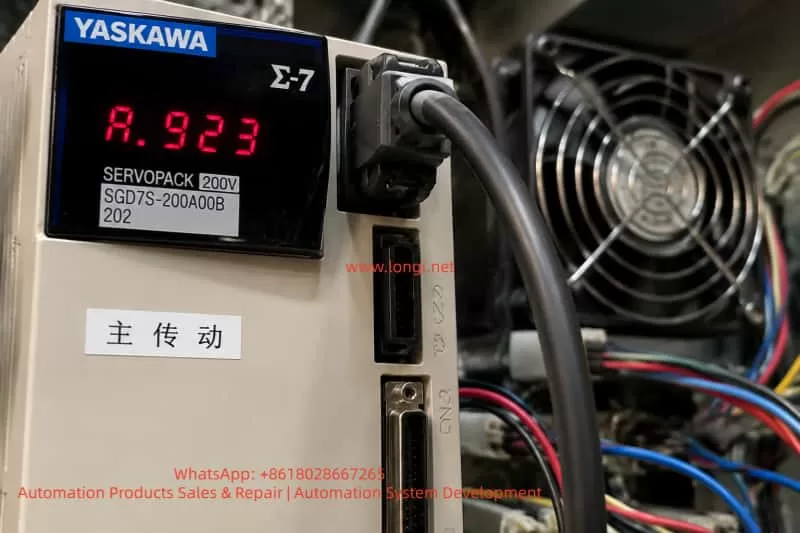
During operation of Yaskawa SERVOPACK servo drives, operators may encounter the A.923 code displayed on the drive panel. This fault is commonly observed in the Sigma series, particularly when the device is running continuously, the control cabinet temperature is high, dust accumulation is significant, or the drive has been in service for an extended period.
The core meaning of A.923 is: the built-in cooling fan in the SERVOPACK has stopped or is operating abnormally. It is a fan-stop warning, not a motor, encoder, overcurrent, or main power circuit failure. Essentially, the servo drive has detected that the internal fan is not operating according to its specifications and is alerting the operator.
Although A.923 does not indicate an immediate catastrophic failure, it should not be ignored. The internal components of the servo drive—including rectifiers, DC bus capacitors, IGBT modules, braking units, power supplies, driver circuits, and control boards—generate heat during operation. If the fan stops, internal temperatures rise, potentially causing overheat alarms, sudden shutdowns, capacitor aging, IGBT module damage, and, in extreme cases, complete power section failure.
Thus, when A.923 occurs, the root cause should be investigated from multiple angles: fan condition, fan power supply, fan signal feedback, duct and cabinet environment, control board detection circuits, and overall cooling conditions.
2. Technical Meaning of A.923
The primary function of the internal fan is to force airflow to dissipate heat from power devices. Medium- and high-power SERVOPACK drives cannot rely solely on natural convection, and the fan ensures effective heat removal from heatsinks, power modules, and the drive enclosure.
A.923 indicates the drive has detected abnormal fan operation. Scenarios include:
Fan completely stopped: On power-up, the fan does not rotate or stops mid-operation.
Fan speed too low: Bearing wear, dust, or blade resistance causes reduced rotation speed. The drive may detect this as abnormal.
Intermittent fan stoppage: Loose connections, broken wiring, or internal fan sensor issues cause the fan to stop sporadically.
Fan rotating but detection signal abnormal: Fan power is fine, but rotation feedback (e.g., FG signal) is missing or incorrect.
Control board detection circuit failure: Even with a working fan, a damaged detection circuit may falsely trigger A.923.
3. Impact on Equipment Operation
A.923 primarily affects the drive’s cooling. Many operators assume that as long as the drive runs, the alarm can be ignored; this is risky.
IGBT modules and DC bus capacitors generate significant heat, especially during frequent acceleration/deceleration. Without fan cooling, heat accumulates, potentially triggering overheat alarms, power module failure, or DC bus capacitor degradation.
Extended operation under A.923 may shorten capacitor life, reduce ripple tolerance, and destabilize power supplies. In production lines, a drive shutdown can halt the entire process, damage materials, or cause mechanical jamming. Therefore, A.923 is a reliability warning that requires timely attention.
4. Common Causes of A.923
4.1 Fan Failure
Bearings wear over time, lubrication declines, and blades experience resistance. Dusty, oily, or high-temperature environments accelerate deterioration.
4.2 Fan Obstruction
Dust, debris, wire ends, or foreign objects can block the fan blade or heatsink, increasing load or stopping rotation.
4.3 Loose Connectors or Wiring
Vibration or maintenance can loosen fan plugs or wires, causing intermittent operation.
4.4 Fan Power Supply Issue
Fans require DC12V or DC24V. Supply failure prevents operation.
4.5 Feedback Signal Abnormal
Fans with FG signals may rotate correctly but fail to provide feedback, causing the drive to detect a fault.
4.6 Control Board Detection Circuit Fault
Damaged board circuits may misinterpret signals or fail to detect fan rotation.
4.7 Poor Cabinet Cooling
Clogged filters, poor ventilation, insufficient spacing, or crowded drives can reduce cooling efficiency and indirectly trigger A.923.
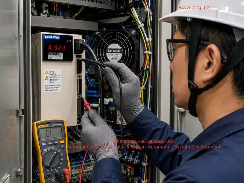
5. On-Site Troubleshooting Procedure
Confirm the alarm code: Ensure the display shows A.923.
Observe fan operation: Safely power up and check if the fan rotates.
Power off and discharge: Wait for DC bus voltage to drop.
Inspect mechanical condition: Check blade smoothness, wear, and obstruction.
Check fan power supply: Measure voltage per fan specifications.
Replace with a compatible fan: Match voltage, feedback type, wiring, and airflow direction.
Check detection signals: Ensure FG or other feedback lines function.
Clear the alarm and test: Verify fan operation and drive temperature under load.
6. Repair Recommendations
For most maintenance personnel:
Clean dust and debris.
Check connectors and wiring.
Replace the fan with the correct specification.
If the alarm persists, inspect fan power supply and control board circuits.
Do not ignore A.923. Continuing operation increases the risk of overheat, shutdown, and component failure.
7. Common Misdiagnoses
Confusing A.923 with motor or encoder failure.
Assuming a visibly spinning fan is always normal.
Using a physically similar but electrically incompatible fan.
Only replacing the fan without cleaning the duct or enclosure.
Continuing operation without intervention.
8. Preventive Maintenance
Periodically clean filters and enclosures.
Inspect fan noise and speed.
Replace aged fans proactively.
Ensure sufficient cabinet ventilation and spacing.
Protect against moisture, oil, and conductive dust.
9. Customer Guidance
Inform customers:
A.923 indicates the internal cooling fan has stopped or has abnormal feedback. It is not a motor or encoder fault. Immediate action is recommended to inspect the fan, clean the duct, and replace the fan if necessary. Persistent alarms may indicate internal drive circuits need repair.
This approach clarifies the issue while avoiding unnecessary concern about motor or drive failure.
10. Conclusion
A.923 is a preventive warning about the cooling system in a Yaskawa SERVOPACK. Proper diagnosis includes verifying fan operation, power supply, feedback, and detection circuits. Most cases involve fan wear, obstruction, loose wiring, or power supply issues. Ignoring A.923 risks overheating, shutdown, and power module damage. Timely intervention ensures stable drive operation and long-term reliability.
Yaskawa SERVOPACK servo drives are widely used in industrial automation equipment. Older Yaskawa series such as SGDM, SGDH, and SGDV are commonly found in CNC machines, printing machines, packaging equipment, semiconductor machinery, handling systems, robotics-related mechanisms, dedicated production lines, and high-precision positioning systems. Because these machines often operate for many years in demanding industrial environments, servo systems may develop alarms, failure to enable, unstable operation, unexpected stopping, or complete axis failure.
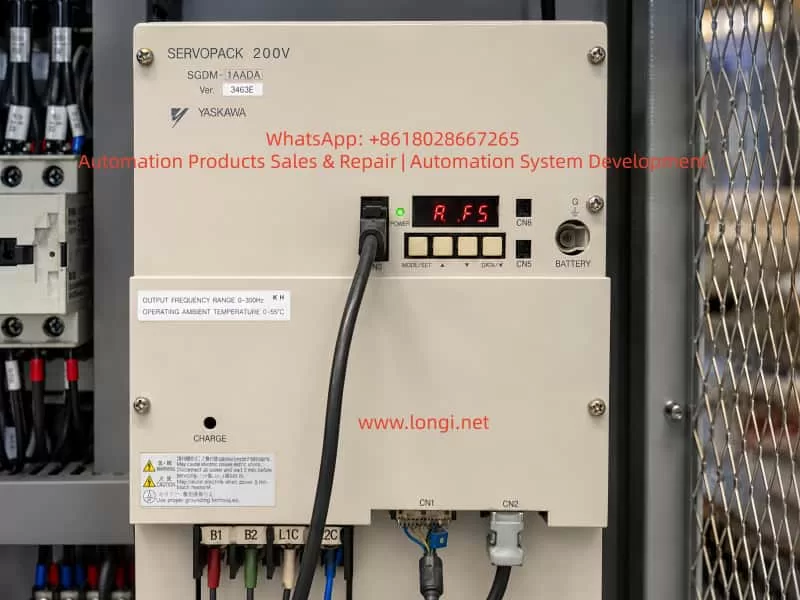
One common fault on the Yaskawa SGDM series is the A.F5 alarm. In many field cases, technicians may see “A.F5” on the display and simply interpret it as “AF5.” Some may immediately assume that the servo drive itself is defective. However, this alarm does not always mean that the SERVOPACK is damaged. In many cases, it points to an abnormal motor power circuit, especially a disconnection or poor contact in the U, V, W motor power lines between the servo drive and the servo motor. It may also be caused by an open motor winding, loose terminal, faulty connector, damaged cable, or an internal output detection or current detection fault inside the servo drive.
From a repair and troubleshooting perspective, the A.F5 alarm should be handled according to the principle of checking the external motor circuit first and the internal drive circuit second. It is not correct to dismantle the drive immediately after seeing A.F5, nor is it correct to only check parameters or control signals. The first priority should be to inspect the motor power cable, motor winding, intermediate terminals, connectors, contactors, drag-chain cables, and the U/V/W output path. Only after the external circuit has been confirmed normal should the internal power output stage and detection circuit of the SERVOPACK be considered.
2. Basic Meaning of the A.F5 Alarm
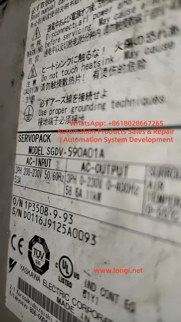
On the Yaskawa SGDM servo drive, A.F5 generally indicates a Servomotor Disconnection Alarm.
It can be understood as:
Servo motor power line disconnection alarm, servo motor connection abnormality alarm, or output circuit abnormality alarm.
The core meaning is that when the drive attempts to control the servo motor, it detects that the motor power circuit is not forming a normal current path, or that the output-side condition does not match the expected state of a normally connected motor. As a result, the drive determines that the motor may not be connected correctly, the power cable may be open, one output phase may be missing, or the internal detection circuit may be abnormal.
It is important to note that A.F5 is not primarily an encoder alarm and is not a general parameter error. A complete servo system includes several parts:
Servo drive main power circuit;
Servo drive control board;
Servo motor;
Motor power cable;
Encoder feedback cable;
Control signal wiring;
Servo ON, limit, emergency stop, and safety circuits;
Mechanical load.
The A.F5 alarm mainly concerns the power output relationship between the servo drive and the servo motor. The key inspection targets are the U, V, and W motor phases and the related output detection circuit.
3. Common Timing of the A.F5 Alarm
Before judging the fault location, it is necessary to confirm when the A.F5 alarm appears. Different alarm timing often indicates different fault directions.
3.1 A.F5 Appears Immediately After Control Power Is Turned On
If the servo drive displays A.F5 immediately after the control power is applied, before the Servo ON signal is given, the fault is more likely related to the internal detection circuit of the drive.
Possible causes include:
Abnormal internal output detection circuit;
Abnormal current detection circuit;
Faulty connection between the power board and control board;
Aging electronic components inside the drive;
Abnormal main circuit detection signal;
Previous output short circuit, explosion, water ingress, moisture damage, or severe overload.
External motor wiring problems cannot be completely ruled out, especially if the motor cable is severely shorted or connected incorrectly. However, if the alarm appears before servo enable, the SERVOPACK itself deserves more attention.
3.2 Power-On Is Normal, but A.F5 Appears After Servo ON
If there is no alarm after power-on, but A.F5 appears when the servo is enabled, when the machine is started, or when the axis is about to run, the external motor power circuit is more suspicious.
This is a very common field situation. Typical causes include:
One phase of U/V/W motor cable is open;
Motor power connector is loose;
Motor terminal box wiring is loose;
Intermediate terminal block has poor contact;
Internal conductor of a drag-chain cable is broken;
Output-side contactor contact is burnt or unreliable;
Servo motor winding is open;
Incorrect wiring after repair, relocation, or modification;
Loose screws on the drive output terminals.
In this case, the correct inspection direction is from the drive output terminals to the motor end, section by section.
3.3 A.F5 Appears Occasionally During Operation
If the equipment can run but occasionally stops with A.F5 after a period of operation, the fault is often intermittent.
Common causes include:
Drag-chain cable conductor is half-broken due to repeated bending;
Motor connector loses contact under vibration;
Terminal block oxidation or looseness;
Motor cable insulation or conductor damage;
Motor winding internal break changes with temperature;
Internal solder joint or connector problem inside the drive;
Poor thermal stability of the current detection circuit.
Intermittent faults are more difficult to locate than fixed faults. Static measurement may appear normal, but the problem may occur only during movement, vibration, or heating. In such cases, cable bending tests, hot-state testing, operation monitoring, and substitution testing are necessary.
4. Difference Between A.F5 Alarm and Encoder Fault
In field maintenance, some technicians tend to classify all servo alarms as “encoder problems.” This is inaccurate. In a Yaskawa servo system, encoder-related alarms usually involve encoder communication, feedback abnormality, encoder disconnection, encoder data error, or battery alarm. The core of A.F5 is not the feedback signal but the motor power output circuit.
The difference can be summarized as follows:
Item
A.F5 Alarm
Encoder-Related Alarm
Main target
Motor power cable U/V/W
Encoder feedback cable
Circuit involved
Main power output, current detection, motor winding
Encoder power, communication, feedback signal
Typical symptom
Alarm after Servo ON, motor does not run
Feedback abnormality, homing error, encoder communication alarm
Therefore, when A.F5 occurs, the inspection should not focus only on the encoder cable, nor should the encoder be replaced blindly. The correct focus should be the motor three-phase power cable and the drive output circuit.
5. Main Causes of the A.F5 Alarm
5.1 Servo Motor Power Cable Disconnection
This is the most direct and common cause. The servo motor power cable normally includes U, V, W phases and PE ground. The drive outputs three-phase PWM voltage through U, V, and W to control the servo motor. If any phase is disconnected, the drive cannot establish normal output current and may trigger A.F5.
The disconnection may occur at:
Drive output terminals;
Cabinet terminal block;
Aviation connector;
Servo motor connector;
Drag-chain cable;
Cable bending point;
Motor terminal box;
Rewired location after repair, relocation, or modification.
This is especially common in machines with moving axes, robotic arms, gantry systems, and drag-chain applications. The cable may look intact externally, but the copper conductor inside may already be half-broken or completely open.
5.2 Loose Terminal or Poor Contact
Loose terminals are common in industrial equipment. Servo drive U/V/W outputs carry fast-changing current. If the terminal is not tight, heating, oxidation, arcing, increased contact resistance, or intermittent disconnection may occur.
Typical signs include:
Blackened terminal;
Discolored cable lug;
Loose terminal screw;
Yellowed or deformed insulation sleeve;
Burnt smell near the terminal;
Alarm becomes more frequent during vibration.
Machines with strong vibration, such as punching feeders, packaging machines, printing machines, woodworking machines, and CNC machine tools, are more likely to develop loose terminals.
5.3 Open Servo Motor Winding
If the motor winding is internally open, the drive will also fail to detect a normal motor load. After power-off, the three-phase motor winding resistance can be measured to make a preliminary judgment.
Measurements should be taken between:
U-V;
V-W;
W-U.
The three resistance values should be close to each other. If one pair shows infinite resistance, the winding or internal lead wire may be open. If the three values are obviously unbalanced, the motor may also have an internal fault.
For large servo motors, the winding resistance can be very low, and ordinary multimeters may not give highly accurate readings. Therefore, the relative balance of the three readings is usually more important than the absolute value.
5.4 Intermediate Contactor or Terminal Block Fault
Some machines use an intermediate contactor, terminal block, plug connector, or safety disconnect device between the servo drive and the motor. In general, it is not recommended to casually install a contactor on the U/V/W output side of a servo drive, because the servo output is a high-frequency PWM waveform and improper switching may cause impact or detection errors.
If the original machine design does include an output-side contactor, the following points should be checked carefully:
Whether the contactor contacts are burnt;
Whether all three phases close reliably and simultaneously;
Whether the contactor coil is energized properly;
Whether terminal blocks are loose;
Whether one phase has high contact resistance;
Whether a safety circuit is incorrectly interrupting the output side.
A contactor may appear conductive during static measurement, but under load its voltage drop may increase, causing the drive to report A.F5.
5.5 Servo Motor Model Mismatch or Incorrect Wiring
Yaskawa servo drives require correct motor matching. If the motor, drive, or cable has been replaced, there may be motor mismatch, wrong phase sequence, or incorrect connector pin definition.
Common wiring mistakes include:
Connecting a motor from a different series to an incompatible drive;
Incorrect U/V/W phase sequence;
Motor power cable connected to wrong terminals;
Input power and motor output mistakenly reversed;
Motor cable connected to braking resistor terminals;
Incorrect pin assignment when using a non-original cable.
Reversing the input power and motor output is especially dangerous and may directly damage the power module. During repair, L1/L2/L3 input terminals and U/V/W output terminals must be clearly distinguished. Wire color alone should not be used as the only basis.
5.6 Internal Power Module Fault
If the external motor, cable, connector, and terminal block are confirmed normal but A.F5 remains, an internal drive fault must be considered.
The SGDM series is an older Yaskawa servo drive family. Many units have been operating for more than ten or even twenty years. Aging components, damaged power modules, cracked solder joints, and current detection drift are all possible.
Common internal problems include:
Damaged IGBT module;
One output phase open internally;
Aging gate driver optocoupler;
Abnormal gate drive circuit;
Current detection circuit fault;
Hall current sensor or shunt resistor fault;
Poor connection between power board and control board;
DC bus voltage detection abnormality;
Output detection comparator circuit fault.
If the drive previously experienced output short circuit, motor cable short circuit, water ingress, heavy dust contamination, capacitor failure, or power module explosion, the probability of internal damage is higher.
5.7 Control Board or Detection Circuit Fault
The A.F5 alarm depends on the internal detection logic of the drive. If the detection circuit itself is faulty, the drive may falsely report motor disconnection even when the external motor cable is normal.
Examples include:
Current sampling signal not reaching the control board;
Damaged operational amplifier;
Abnormal isolated feedback signal;
Comparator output error;
Changed value of analog sampling resistor;
Damaged control board input channel;
Poor contact in board-to-board ribbon cable or connector.
This type of fault usually requires professional bench repair, circuit measurement, signal tracing, substitution testing, and oscilloscope analysis.
6. Correct Field Troubleshooting Procedure
Step 1: Record the Alarm Condition
Before troubleshooting, record the following information:
Servo drive model;
Servo motor model;
Alarm code;
Whether the alarm appears at power-on or after Servo ON;
Whether the alarm occurs intermittently during operation;
Whether the motor, cable, or drive was repaired or replaced before;
Whether the machine was relocated, rewired, flooded, shorted, or overloaded;
Whether abnormal noise, smell, breaker trip, or mechanical jamming occurred before the alarm.
These details help narrow down the fault quickly.
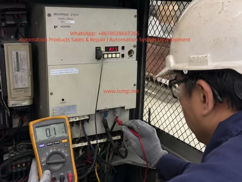
Step 2: Power Off and Confirm DC Bus Discharge
There is a high-voltage DC bus inside the servo drive. Even after power is turned off, the capacitors may retain dangerous voltage. Before checking U/V/W terminals or opening the drive, the main power must be disconnected and the DC bus voltage must be confirmed safe.
Safety requirements include:
Turn off the machine main power;
Wait until the CHARGE indicator goes out;
Use a multimeter to confirm that the DC bus voltage has dropped to a safe level;
Do not touch main circuit terminals directly;
Do not plug or unplug motor or encoder cables while powered;
Do not disconnect U/V/W wiring while the drive is enabled.
The servo output side carries high-frequency PWM voltage. Live operation can cause electric shock, short circuit, or secondary damage.
Step 3: Inspect the U/V/W Output Terminals
Check the motor output terminals at the bottom of the drive:
U;
V;
W;
PE ground.
Inspection items include:
Whether terminal screws are loose;
Whether cable lugs are tightly pressed;
Whether terminals are burnt or blackened;
Whether cables are detached;
Whether wiring is incorrect;
Whether wire numbers match the drawing;
Whether copper strands are exposed and causing short circuit;
Whether oil, dust, or metal chips are present.
If loose terminals are found, re-crimp the cable lug, clean oxidation, and tighten the terminal. If cable lugs or terminal blocks are already burnt, they should be replaced rather than simply tightened.
Step 4: Measure Motor Winding Resistance
Disconnect the U/V/W motor cable from the drive and measure the motor-side three-phase winding resistance.
Measurement
Judgment
U-V
Should show low resistance
V-W
Should show low resistance
W-U
Should show low resistance
Comparison of three values
Should be basically balanced
One pair reads infinite
Possible winding open circuit or cable break
One pair obviously higher
Possible poor contact or winding abnormality
If the measurement is taken at the drive end, the result includes both the cable and motor. If abnormal, continue measuring at the motor connector or motor terminal box to distinguish cable fault from motor fault.
Step 5: Measure Insulation to Ground
Although A.F5 mainly indicates a disconnection alarm, insulation should also be checked. Damaged cable insulation or motor winding leakage may cause other alarms or indirectly affect the drive detection.
Use a megohmmeter to measure:
U to PE;
V to PE;
W to PE;
Motor winding to motor housing.
For a servo motor and cable, insulation should be high. If insulation is low, the motor, cable, or connector may be damp, damaged, contaminated, or aged.
Important: the servo drive must be disconnected before using a megohmmeter. Never apply megger voltage directly to the drive electronics, as this may damage the drive.
Step 6: Inspect Motor Connector and Intermediate Connectors
Servo systems often use aviation plugs or special connectors. Connector faults are common, especially in environments with oil mist, coolant, dust, and vibration.
Check for:
Bent pins;
Pins pushed backward;
Connector not locked;
Oil or water inside the connector;
Oxidized or blackened pins;
Poor shield termination;
Cable strain at connector tail;
Loose crimping inside the plug.
If oil or water has entered the connector, simply blowing it dry may not be reliable. The connector should be cleaned, dried, re-crimped, or replaced if necessary.
Step 7: Inspect Drag-Chain Cable
For moving axes, the drag-chain cable is a key suspect. Drag-chain cable damage can be hidden, and static measurement may not reveal it.
Practical checking methods include:
Measure continuity while bending the cable;
Move the machine to different positions and measure again;
Check whether the alarm only occurs at a certain axis position;
Temporarily bypass the drag-chain cable with another motor cable;
Check whether the bending radius is too small;
Inspect for clamping, pulling, or mechanical damage.
If A.F5 disappears after bypassing the original cable, the original cable or intermediate connector is very likely faulty.
Step 8: Use Substitution Testing to Identify Motor or Drive Fault
If there is another same-model axis or spare equipment on site, substitution testing can be used, but it must be done carefully.
Possible methods include:
Connect a known-good motor to the suspected drive;
Connect the suspected motor to a known-good drive;
Swap motor power cables;
Swap encoder cables;
Swap drives.
Before substitution, confirm that voltage, power rating, motor model, encoder type, and parameters are compatible. Randomly connecting different motor and drive models may cause damage.
Typical conclusions are:
If the fault follows the motor, the motor or motor cable is faulty;
If the fault follows the drive, the drive is faulty;
If the fault follows the cable, the cable or connector is faulty;
If the fault disappears after reconnection, there may have been poor contact.
7. Internal Repair Logic of the Servo Drive
When the external motor cable, motor winding, connector, and terminal block are all confirmed normal but A.F5 remains, the drive should be inspected internally.
7.1 Check the Power Module
The SGDM servo drive uses an internal power module or IGBT output structure. During repair, check:
Whether the P-N DC bus is shorted;
Whether U/V/W to P or N show abnormal short circuit;
Whether the IGBT bridge diode characteristics are normal;
Whether one output phase is open;
Whether the module has cracks, burns, or explosion marks;
Whether the module base shows overheating discoloration.
If the IGBT module is damaged, replacing a fuse or simply resetting the alarm is not enough. The gate drive circuit, motor cable, and load must also be checked, otherwise the new module may fail again.
7.2 Check the Gate Drive Circuit
The IGBT gate drive circuit controls the switching of the power module. If the drive signal is abnormal, output current cannot be established correctly, and the system may judge the motor as disconnected or output abnormal.
Inspection points include:
Whether gate drive power supply is normal;
Whether upper and lower bridge gate signals are normal;
Whether driver optocouplers are damaged;
Whether gate resistors are open or changed in value;
Whether protection diodes are shorted;
Whether the driver board is burnt;
Whether board-to-board connectors are reliable.
This area usually requires an oscilloscope and isolated measurement conditions. It is not recommended for untrained field personnel to test blindly.
7.3 Check the Current Detection Circuit
The servo drive often depends on output current feedback to judge motor connection status. If the current detection circuit fails, the control board may interpret the output as abnormal even if the power module is working.
Common detection components include:
Current transformer;
Hall current sensor;
Shunt resistor;
Operational amplifier;
Comparator;
A/D input channel;
Isolation amplifier;
Signal filter circuit.
If one phase current feedback is missing, the drive may falsely report motor disconnection or output phase loss.
7.4 Check the Connection Between Control Board and Power Board
A common issue in older drives is oxidized board connectors, poor ribbon-cable contact, or cracked solder joints. This is especially common in high-temperature, dusty, oily, or vibrating environments.
Check:
Oxidized connectors;
Loose ribbon cables;
Cracked solder joints;
Warped circuit boards;
Blackened pins;
Electrolytic capacitor leakage corrosion;
Conductive dust contamination.
For old drives, cleaning the boards, reseating connectors, and re-soldering suspicious joints may solve intermittent alarms.
8. Common Misjudgments During Repair
8.1 Looking Only at the Alarm Code and Ignoring Alarm Timing
The same A.F5 alarm can have different causes depending on whether it appears at power-on, after Servo ON, or during operation. Ignoring timing can lead to the wrong troubleshooting direction.
8.2 Checking Only the Encoder Cable Instead of the Motor Power Cable
The key circuit of A.F5 is not the encoder cable but the motor power circuit. The encoder cable can be inspected, but it should not be treated as the main target.
8.3 Assuming the Cable Is Good Because a Multimeter Shows Continuity
A half-broken drag-chain cable may appear conductive during static measurement but open during movement. For intermittent alarms, dynamic bending tests or temporary cable replacement are necessary.
8.4 Using a Megohmmeter Without Disconnecting the Drive
Megger voltage can damage drive electronics. When measuring motor or cable insulation, the drive side must be disconnected first.
8.5 Replacing the Drive Blindly
If the root cause is a motor cable break, short circuit, or motor winding fault, replacing the drive may not solve the problem and may even damage the replacement drive.
8.6 Ignoring Mechanical Jamming
Although A.F5 mainly indicates a motor connection abnormality, severe mechanical jamming may cause abnormal servo current and mislead troubleshooting. The mechanical axis, brake release, and load condition should also be checked.
9. Recommended Standard Troubleshooting Flow
For a Yaskawa SGDM servo drive with A.F5 alarm, the following sequence is recommended:
Confirm that the displayed alarm is A.F5;
Record when the alarm appears;
Power off and confirm DC bus discharge;
Check the drive U/V/W output terminals;
Check the motor power wiring;
Measure the three-phase motor winding resistance;
Measure motor and cable insulation to ground;
Inspect motor connector, terminal block, and intermediate contactor;
Check whether drag-chain cable conductors are broken;
Temporarily bypass intermediate wiring for testing;
Use substitution testing to distinguish motor, cable, and drive;
After confirming the external circuit is normal, inspect the drive internally;
Check IGBT, gate drive circuit, current detection circuit, power board, and control board;
Perform no-load testing after repair;
Connect the motor and run at low speed;
Finally restore machine load and test normal operation.
The principle is:
External before internal; simple before complex; low-risk checks before dismantling; root cause confirmation before replacing parts.
10. Key Tests After Repair
After repairing an A.F5 fault, it is not enough to confirm that the alarm disappears. A complete test should be performed.
10.1 Static Test
Check:
Drive powers on without alarm;
Control power is normal;
Main power is normal;
DC bus voltage is normal;
Cooling fan operates normally;
No abnormal sound or smell.
10.2 Servo Enable Test
After applying Servo ON, observe:
Whether A.F5 reappears;
Whether the motor becomes energized;
Whether the brake releases properly;
Whether the motor vibrates;
Whether current is abnormal;
Whether overcurrent, overload, or encoder alarms appear.
10.3 Low-Speed Run Test
Run the motor forward and reverse at low speed and observe:
Whether the rotation direction is correct;
Whether operation is smooth;
Whether there is abnormal noise;
Whether current is balanced;
Whether speed feedback is stable;
Whether stopping is normal.
10.4 Load Test
After restoring the machine load, test:
Acceleration and deceleration;
Positioning accuracy;
Long-term operation;
Whether drag-chain movement affects the alarm;
Motor and drive temperature rise;
Whether terminals become hot.
Only after the machine runs continuously without the alarm should the repair be considered complete.
11. Preventive Maintenance Recommendations
For older Yaskawa SGDM servo systems, regular maintenance can reduce the occurrence of A.F5 and similar alarms.
11.1 Tighten Terminals Regularly
Input terminals, output terminals, motor terminal boxes, and cabinet terminal blocks should be checked regularly. In high-power servo systems, loose terminals can cause heating, burning, and poor contact.
11.2 Inspect Drag-Chain Cables Regularly
Drag-chain cables are consumable parts. Bending points, fixing points, and moving sections should be inspected frequently. Cables beyond their service life should be replaced in advance.
11.3 Keep the Electrical Cabinet Clean
Dust, oil mist, and metal particles can contaminate circuit boards and terminals. Electrical cabinets should be kept clean, dry, and well ventilated.
11.4 Prevent Oil and Water from Entering the Motor
Servo motor connectors, motor terminal boxes, and cable entry points should be protected from coolant, oil, and moisture. This is especially important for machine tools, cleaning equipment, and food packaging machines.
11.5 Avoid Random Switching on the Output Side
Do not casually install contactors, switches, or plug-in structures on the U/V/W output side of the servo drive. If output switching is required by machine design, it must follow proper servo system rules and only switch when the drive is stopped and has no output.
11.6 Mark Wires Clearly After Maintenance
Many servo faults occur after incorrect reconnection. Before disconnecting wires, take photos, mark wire numbers, and record terminal positions. During reassembly, do not rely only on wire color. Always verify according to the drawing and terminal definition.
12. Conclusion
The A.F5 alarm on a Yaskawa SGDM servo drive is essentially a servomotor disconnection or output circuit abnormality alarm. It should not be simply interpreted as “the drive is bad,” nor should the troubleshooting focus only on the encoder or parameters. The correct analysis should focus on the motor power circuit, especially the U/V/W output cable, motor winding, terminal block, connector, drag-chain cable, intermediate contactor, and the internal output detection and power drive circuits of the SERVOPACK.
In practical repair work, if A.F5 appears after Servo ON, the external motor cable, motor winding, connector, and terminal contact should be suspected first. If A.F5 appears immediately after control power is applied, or if the external circuit is fully confirmed normal but the alarm remains, the internal power module, current detection circuit, gate drive circuit, and control board should be inspected.
For old SGDM servo drives, long service life often leads to aging electronic components, poor board contact, and deterioration of the power section. Therefore, successful troubleshooting requires both field electrical diagnosis and electronic repair capability. A systematic process should be followed: alarm timing analysis, external circuit inspection, motor winding measurement, dynamic cable testing, substitution verification, and internal drive inspection.
Although A.F5 appears to be a simple alarm code, it involves the servo system’s power output, motor connection, current detection, and protection logic. For maintenance personnel, the key is not only to remember the alarm code, but to understand the detection logic and fault chain behind it. Only then can the root cause be located quickly, repair efficiency improved, unnecessary part replacement avoided, and machine downtime reduced.
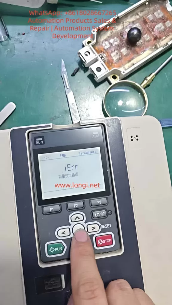
When servicing, commissioning, or restoring parameters on a Yaskawa GA700 inverter, technicians may encounter a common but easily misunderstood problem: when setting A1-03 = 2220 to perform 2-wire sequence initialization, the keypad does not complete initialization and instead displays iErr, meaning capacity setting error.
This error is often misjudged as a wrong key operation, insufficient access level, keypad failure, or corrupted software. In reality, for the GA700 series, the key issue is usually not A1-03 itself, but a mismatch between the inverter’s internal capacity setting and the actual power unit.
Yaskawa GA700 control boards have a certain level of interchangeability. In repair work, a control board may be taken from another GA700 unit and installed onto a different power section. However, “physically compatible” does not mean “automatically matched.” The control board must know the correct inverter capacity. If the capacity code stored in the control board does not match the actual power unit, the inverter may power up and display normally, but initialization, auto-tuning, or operation may fail.
1. What A1-03 = 2220 Actually Does
In GA700 parameters, A1-03 is the initialization parameter.
When A1-03 = 2220 is executed, the inverter restores many parameters to factory settings and assigns terminals S1 and S2 as forward run and reverse run inputs. However, this does not mean every parameter is reset. Several fundamental parameters are excluded from normal initialization, including capacity-related settings such as o2-04.
The important point is that “factory setting” is not one fixed parameter set for all GA700 drives. A 5.5 kW inverter, a 15 kW inverter, a 22 kW inverter, and a 75 kW inverter cannot share the same rated current, carrier frequency limit, overload curve, motor default values, or protection settings. Therefore, before the inverter can restore factory settings, it must first know its correct model and capacity.
If the capacity information is wrong, initialization cannot be safely completed.
2. The Real Meaning of iErr Capacity Setting Error
The iErr message is not a normal running fault such as overcurrent, overvoltage, undervoltage, or overload. It is closer to a parameter-processing error caused by failed capacity verification.
In simple terms, the inverter detects that:
the control board thinks it belongs to one capacity, but the actual power unit appears to be another capacity, or the capacity selection parameter has not been correctly written.
As a result, the inverter cannot safely generate the correct factory parameter set, so it refuses to complete initialization and displays iErr.
This protection logic is reasonable. If the inverter uses the wrong capacity data, it may apply the wrong rated current, wrong overload protection, wrong module thermal protection, wrong carrier frequency limit, and wrong control gain. The result may range from poor performance to IGBT damage, driver board damage, current detection errors, or motor damage.
The key parameter is:
o2-04 — Inverter Capacity Selection
This parameter sets the inverter model/capacity. After replacing the control circuit board, o2-04 must be correctly set according to the actual inverter model. If o2-04 is wrong, the protection functions may not operate correctly, and the inverter may be damaged.
Therefore, when A1-03 = 2220 causes iErr, the first parameter to check is not A1-03, but o2-04.
3. Why This Happens After Replacing the Main Control Board
Many technicians know that Yaskawa inverter control boards are often partly universal within the same series. This is true, but it must not be misunderstood.
The correct understanding is:
The control board may be hardware-compatible, but its capacity setting must match the actual power unit.
A GA700 inverter’s identity is determined by several items together:
Nameplate model;
Input voltage class;
Rated output current;
Power unit specification;
Control board software version;
o2-04 inverter capacity selection;
C6-01 heavy-duty/light-duty selection;
Capacity-dependent factory parameters.
If a control board is replaced but o2-04 is not corrected, the inverter may still power up, enter menus, and accept some parameter changes. However, problems may appear during initialization, auto-tuning, or trial operation. iErr during A1-03=2220 is a typical symptom.
4. o2-04 Is the Core Parameter
o2-04 is not a motor power parameter. It is not a parameter where the technician simply enters a motor kW value. It is a capacity selection code corresponding to the actual GA700 inverter model.
This value must be selected according to the inverter nameplate model, not according to the motor power at the site.
5. What Happens If o2-04 Is Set Incorrectly
Some people think the capacity parameter only affects the displayed model or rated power. This is dangerous.
An incorrect o2-04 setting may affect:
Rated Current Judgment
The drive’s overload protection, electronic thermal protection, and current limit are based on the correct inverter rated current. If a 15 kW inverter is set as a 7.5 kW unit, it may trip too early. If a 7.5 kW inverter is set as a 15 kW unit, protection may become too slow, and the power module may be damaged.
Carrier Frequency Limit
Different capacity drives have different allowable carrier frequency ranges. Larger drives generate more heat, and an excessive carrier frequency may cause the IGBTs to overheat.
Motor Default Parameters
After initialization, motor rated capacity, motor rated current, V/f base values, and other defaults may depend on the inverter capacity.
Protection Curves
Overload, overheat, module protection, and braking protection are all related to capacity. A wrong capacity setting may make protection inaccurate.
Control Performance
Vector control, current loop response, speed loop response, torque response, and low-speed performance all require correct capacity-based settings. If the capacity is wrong, the drive may still run, but it may show poor torque, vibration, overcurrent, unstable speed, or acceleration failure.
6. Correct Field Repair Procedure
When A1-03=2220 displays iErr, follow this procedure.
Step 1: Stop Repeating Initialization
Do not keep entering A1-03=2220. If the capacity data is wrong, repeating the same operation will not solve the problem.
Step 2: Check the Inverter Nameplate
Record the complete model number, especially:
Full inverter model;
Voltage class;
Rated output current;
Rated power;
Production information;
Whether it is a special version.
Example:
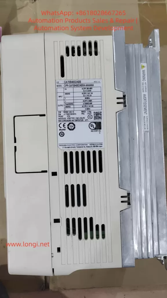
CIPR-GA70B4031xxxx
The key section is 4031.
Step 3: Set Parameter Access Level
Set:
A1-01 = 2
This allows access to advanced parameters. If the access level is too low, some parameters may not be visible or editable.
Step 4: Check Current o2-04
Enter parameter o2-04 and check whether the displayed value matches the nameplate model suffix.
If the value is obviously different, this is very likely the cause of iErr.
Step 5: Correct o2-04
Set o2-04 according to the actual inverter model.
After changing o2-04, power off the inverter. Wait until the CHARGE indicator is completely off and the DC bus voltage has dropped to a safe level. Then power on again.
This restart allows the drive to reload capacity-related internal settings.
Step 6: Execute A1-03 = 2220 Again
After power cycling, set:
A1-03 = 2220
If the capacity setting was the cause, initialization should now complete normally.
After initialization, recheck:
A1-02 control method;
C6-01 heavy-duty/light-duty selection;
Motor rated voltage;
Motor rated current;
Motor rated frequency;
Motor rated speed;
Run command source;
Frequency reference source;
Acceleration/deceleration time;
Multi-function terminal settings.
Do not assume that the drive is ready for load operation immediately after initialization. Application parameters must still be set correctly.
7. If iErr Still Appears After Correcting o2-04
If o2-04 matches the nameplate but A1-03=2220 still causes iErr, check deeper hardware and data issues.
Control Board and Power Board Version Mismatch
The control board may not be suitable for this voltage class, capacity range, or hardware version. Similar appearance does not guarantee compatibility.
Power Board Identification Circuit Problem
Some drives read capacity-related information from the power section, driver board, or internal identification circuit. Check:
Control board-to-driver board ribbon cable;
Connector oxidation;
Bent pins;
Loose or reversed cable connection;
Low-voltage supply on the driver board;
Identification resistors or related circuits.
EEPROM or Parameter Memory Error
If the drive has been affected by water, lightning, abnormal control power, failed repair, or incorrect programming, parameter memory may be corrupted. In this case, keypad operation may not be enough. The unit may require engineering software, special tools, EEPROM repair, or control board replacement.
Unknown Second-Hand Assembly
Used drives may be assembled from different units. The outer nameplate, control board, power board, and keypad may not belong to the same original inverter. In such cases, the technician must identify the actual power section rather than blindly trusting the nameplate.
Incorrect Capacity Code Entry
o2-04 values are not simple decimal numbers. Codes such as 9A, 9C, 9F, and A1 must be entered exactly. Misreading or mistyping these values will continue to cause problems.
8. Example Case
Suppose the nameplate shows:
CIPR-GA70B4031
This is a 400 V class GA700 with model suffix 4031. The corresponding o2-04 setting is 9C.
If a technician installs a control board taken from a GA70B4060, that control board may still store o2-04 = 9F. The drive may power on normally, but when A1-03=2220 is executed, it displays iErr.
The correct repair is:
Set A1-01 = 2;
Set o2-04 = 9C;
Power off and wait until the CHARGE light goes out;
Power on again;
Set A1-03 = 2220;
Reconfigure motor and application parameters.
If the initialization succeeds after this procedure, the original problem was capacity mismatch.
9. Common Mistakes to Avoid
Do not set o2-04 to a larger capacity just to avoid overload trips. This may delay protection and damage the inverter.
Do not set o2-04 according to motor power. It must be set according to the inverter’s actual model and power unit.
Do not assume initialization can fix capacity mismatch. Initialization itself depends on correct capacity data.
Do not skip power cycling after changing o2-04.
Do not ignore C6-01. Heavy-duty/light-duty selection affects rated current and overload characteristics.
10. Trial Operation After Repair
After correcting the capacity setting and completing initialization, perform a staged test.
First, power on the drive without load. Confirm that there is no fault, the keypad displays normally, the fan works normally, DC bus voltage is normal, and there is no abnormal smell or noise.
Second, check basic parameters, including:
A1-02 control method; b1-01 frequency reference source; b1-02 run command source; C1-01 acceleration time; C1-02 deceleration time; E1-01 input voltage setting; E1-04 maximum output frequency; E2-01 motor rated current; C6-01 heavy-duty/light-duty selection.
Third, run the motor without mechanical load at low frequency, such as 5 Hz, 10 Hz, and 20 Hz. Observe output current balance, motor rotation direction, vibration, and any abnormal alarm.
Fourth, gradually apply load. Do not immediately start with full load.
Fifth, perform motor auto-tuning if vector control or high-performance operation is required.
11. Professional Explanation for Customers
A clear explanation to the customer can be:
When the Yaskawa GA700 displays iErr during A1-03=2220 initialization, it indicates a capacity setting error. This is usually not caused by incorrect keypad operation or by the initialization command itself. The more likely cause is that the control board’s inverter capacity selection does not match the actual power unit. Although the GA700 control board has some interchangeability, after replacing the control board, parameter o2-04 must be set according to the actual inverter model. If the capacity setting is wrong, the drive cannot safely generate the correct factory parameter set, so it refuses initialization and displays iErr. The correct repair is to verify the nameplate model, set the proper o2-04 capacity code, power cycle the drive, and then execute A1-03=2220 again.
12. Conclusion
When a Yaskawa GA700 inverter reports iErr while setting A1-03=2220, the key point is not the initialization command itself but the inverter capacity selection parameter o2-04.
The GA700 control board may be reusable across certain models, but it must be matched to the actual power unit through the correct capacity code. If o2-04 is wrong, the inverter cannot safely restore factory parameters and will report a capacity setting error.
The correct repair logic is:
Check the inverter nameplate, identify the model suffix, set the correct o2-04, power cycle the inverter, execute A1-03=2220, then reconfigure motor parameters and perform trial operation.
This fault looks like an initialization failure, but its real cause is usually a mismatch between the control board identity and the actual power unit capacity. For used GA700 drives, repaired units, replaced control boards, and mixed assemblies, this point is especially important.
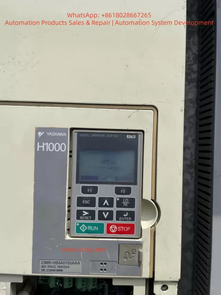
In industrial automation control systems, inverters serve as the core equipment for motor drive, and their stability directly impacts the continuous operation of production lines. The Yaskawa H1000 series inverter, renowned for its high-precision vector control, rich functional expansion, and reliable hardware design, is widely used in scenarios such as fans, pumps, conveyor belts, and machine tools. However, in practical maintenance, the OPE04 fault (Motherboard Replacement Detection Fault) is one of the most common issues encountered by technicians—it can be triggered by either actual motherboard replacement or hardware contact failures/system false alarms. If mishandled, this fault may render the inverter unable to start normally, even affecting the efficiency of the entire production line.
This article delves into the essence of the OPE04 fault, hardware logic, and software mechanisms to provide technicians with scenario-based troubleshooting processes, preventive maintenance strategies, and practical case validations. The goal is to help technicians quickly locate issues, standardize operations, and ensure the inverter returns to stable operation.
2. Definition and Triggering Mechanism of OPE04 Fault
2.1 Official Interpretation of the Fault Code
According to the Yaskawa H1000 series inverter manual, OPE04 stands for “Board Replace Detect” (Motherboard Replacement Detection). Its core meaning is: The inverter’s control system detects a change in the control motherboard and requires an initialization operation to confirm the motherboard replacement status.
In simple terms, this is a “self-protection mechanism” of the inverter—the control motherboard is the “brain” of the inverter, storing user-defined parameters (e.g., motor rated power, acceleration/deceleration time, vector control parameters), operation logic (e.g., V/F curve, PID adjustment), and communication configurations (e.g., Modbus, Profibus). When the motherboard is replaced, the default parameters of the new motherboard may conflict with the original system parameters. Without “confirmation,” the inverter cannot guarantee operational consistency, so it triggers the OPE04 fault to force the user to complete initialization.
2.2 Triggering Scenarios for OPE04 Fault
The OPE04 fault is triggered in two categories: active scenarios and passive scenarios:
Active Scenario: The user proactively replaces the control motherboard due to damage (e.g., capacitor breakdown, chip burnout) or functional upgrades (e.g., replacing with a motherboard supporting a higher communication protocol).
Passive Scenario: No proactive motherboard replacement occurs, but the system falsely detects a “motherboard replacement” due to hardware contact failures (e.g., loose motherboard connectors, oxidation) or motherboard firmware abnormalities (e.g., program runaway).
3. Hardware Root Causes of OPE04 Fault: The “Core Status” and Replacement Specifications of the Control Motherboard
3.1 Functions and Structure of the Control Motherboard
The control motherboard (usually marked as the “CPU board”) of the Yaskawa H1000 inverter is the control center of the entire system. Its core components include:
CPU Chip: Responsible for calculating control algorithms (e.g., vector control, PID adjustment) and processing user commands (e.g., start/stop, frequency setting).
Memory Chips: Divided into non-volatile memory (e.g., EEPROM, stores user parameters) and volatile memory (e.g., RAM, stores runtime data).
Interface Circuits: Connects the power board, driver board, operation panel, and external devices (e.g., sensors, PLCs) to enable signal transmission and communication.
If the motherboard is damaged, the inverter loses all control capabilities (e.g., unresponsive to operation panel commands, motor failure to start) and must be replaced.
3.2 Standardized Operations for Motherboard Replacement
When replacing the control motherboard, the following steps must be strictly followed to avoid subsequent faults:
Power-Off Operation: Cut off the inverter’s input power (including main power and control power) and wait 5–10 minutes to discharge the DC bus capacitor (to avoid electric shock or damage to the new motherboard).
Anti-Static Measures: Wear an anti-static wrist strap to prevent electrostatic discharge (ESD) from damaging sensitive components on the motherboard (e.g., CMOS chips).
Connector Installation: The connection between the motherboard and the base plate usually uses pin headers + sockets or flat cables. Ensure the connector is fully inserted and not skewed (check the positioning marks on the connector).
Fixing Screws: Use a suitable screwdriver to tighten the fixing screws—avoid over-tightening (which may deform the motherboard) or under-tightening (which may cause poor contact).
4. Software Logic of OPE04 Fault: The “Necessity” and “Operation Process” of Initialization
4.1 Why Is “Motherboard Replacement Confirmation” Required?
The parameter system of the Yaskawa H1000 inverter uses a double-layer structure of “factory parameters + user parameters”:
Factory Parameters: Stored in the motherboard’s non-volatile memory, these are the “default configurations” of the inverter (e.g., Pr. 0 = 0 for V/F control; Pr. 1 = 60Hz for rated frequency).
User Parameters: Parameters modified by the user based on actual applications (e.g., Pr. 3 = 380V for motor rated voltage; Pr. 7 = 5s for acceleration time), usually stored in EEPROM.
When replacing the motherboard, the factory parameters of the new motherboard may conflict with the user parameters of the original system (e.g., the original system uses vector control, but the new motherboard defaults to V/F control). Without “confirmation,” the inverter may fail to operate normally (e.g., motor start failure, speed fluctuations). Therefore, Yaskawa designs the “motherboard replacement confirmation” function to allow the system to recognize the new motherboard and load correct parameters by modifying specific parameters (e.g., Pr. 777).
4.2 Initialization Process After Motherboard Replacement (Core Steps)
If the OPE04 fault is triggered by proactive motherboard replacement, follow these steps to complete initialization (taking the Yaskawa H1000 series as an example; details may vary by firmware version—refer to the corresponding manual):
Step 1: Prepare Work
Backup Original Parameters (if possible): If the original motherboard is not completely damaged, back up user parameters via the operation panel or Yaskawa’s dedicated software (e.g., DriveWizard) to avoid losing critical configurations after initialization.
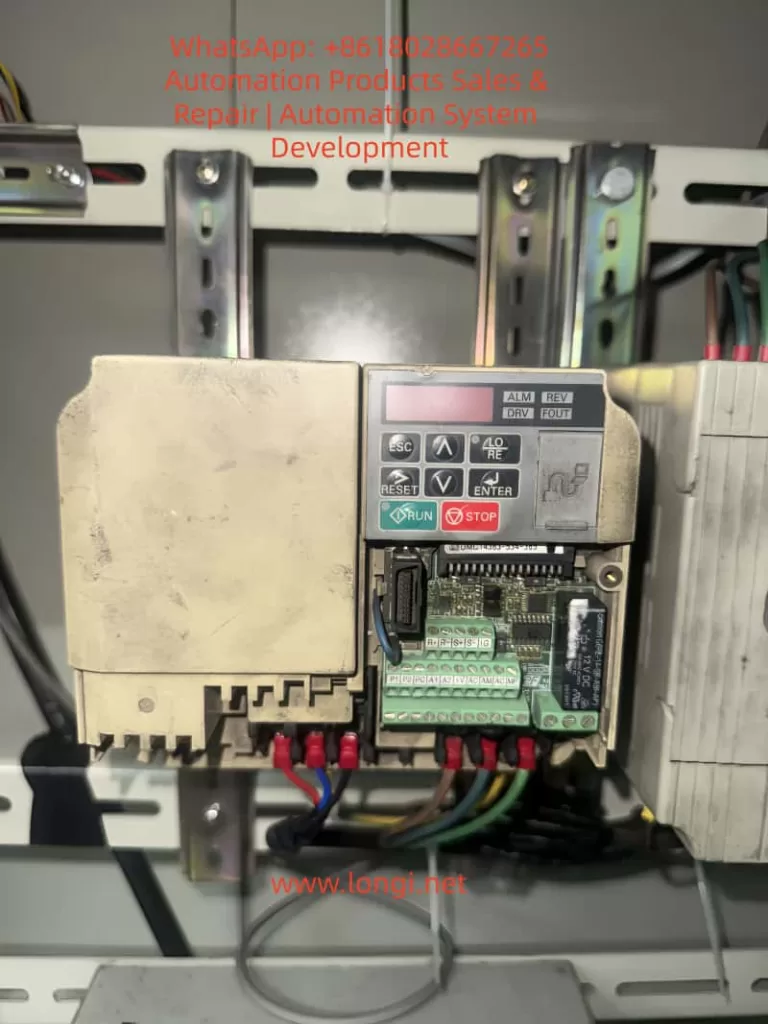
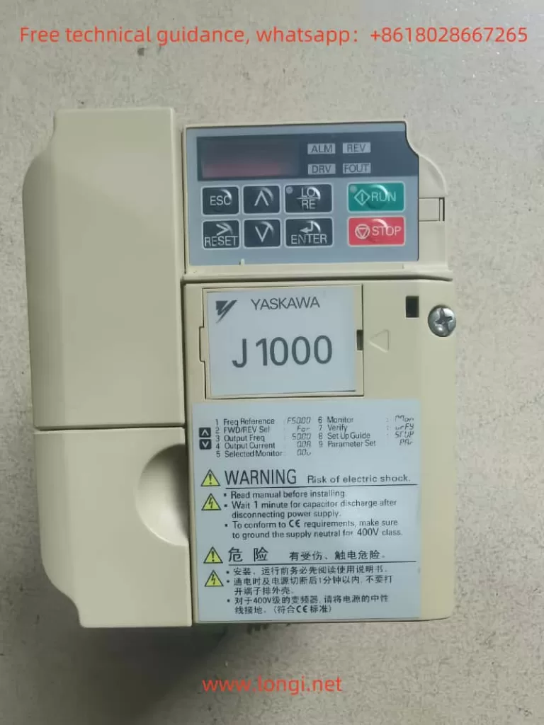
Tool Preparation: Phillips screwdriver, anti-static wrist strap, operation panel (JVOP-180, the digital operator in the picture).
Step 2: Enter Parameter Mode
Press the ESC key to exit the fault display and return to standby (screen shows “STOP”).
Long-press the MODE key (for ~3 seconds) until the screen displays “Pr. 0” (indicating entry into parameter mode).
Step 3: Locate the “Motherboard Replacement Confirmation” Function Code
The “motherboard replacement confirmation” function code for the Yaskawa H1000 series is usually Pr. 777 (some versions may use Pr. 778 or others—refer to the manual). The parameter values mean:
0: Motherboard replacement not confirmed (default, triggers OPE04 fault).
Use the ↑/↓ keys to change Pr. 777 from “0” to “1”.
Press the ENTER key to confirm the modification (screen shows “Pr. 777=1”).
Step 5: Restart the Inverter
Cut off the inverter power and wait 1 minute before re-energizing.
After power-on, if the screen shows “RUN” or “STOP” (no fault code), the initialization is successful, and the OPE04 fault is eliminated.
5. Troubleshooting OPE04 Fault Without Motherboard Replacement: Hardware Contact and System False Alarms
If the OPE04 fault is triggered without proactive motherboard replacement, it is usually caused by hardware contact failures or system false alarms. Follow these steps to troubleshoot:
5.1 Check Hardware Contact Failures
Step 1: Disconnect Power
Cut off the inverter’s input power and wait for the DC bus capacitor to discharge (use a multimeter to measure the DC bus voltage to ensure it is below 36V).
Step 2: Open the Inverter Casing
Use a Phillips screwdriver to remove the casing fixing screws and open the cover (avoid damaging internal components).
Step 3: Inspect Motherboard Connections
Locate the connector between the control motherboard and the base plate (usually on the edge of the motherboard, marked as “CN1” or “CN2”).
Gently pull out the connector and check if the pins are oxidized (e.g., blackened pin surface), bent (e.g., skewed pins), or dirty (e.g., dust, oil).
Wipe the pins and socket with anhydrous alcohol (do not use gasoline or acetone to avoid corrosion). After the alcohol evaporates, reinsert the connector (ensure full insertion, no skewness).
Step 4: Reinstall the Casing and Power On
Reinstall the casing and tighten the fixing screws.
After power-on, if the OPE04 fault disappears, the problem is solved; if not, proceed to the next step.
5.2 Restore Factory Settings (Caution!)
If the hardware contact is good but the fault persists, it may be a system parameter conflict causing a false alarm. You can try restoring factory settings (note: this operation clears all user parameters—back up first):
Step 1: Enter Parameter Mode
Press the ESC key to exit the fault display and long-press the MODE key to enter parameter mode.
Step 2: Locate the “Restore Factory Parameters” Function Code
The “restore factory parameters” function code for the Yaskawa H1000 series is usually Pr. 778. The parameter values mean:
0: Keep current parameters (default).
1: Restore factory parameters (clears all user parameters).
Step 3: Restore Factory Parameters
Use the ↑/↓ keys to change Pr. 778 to “1”.
Press ENTER to confirm— the screen will show “Pr. 778=1” (indicating restoration in progress).
Wait ~10 seconds until the screen shows “END” (restoration completed).
Step 4: Reconfigure Parameters and Verify
Reconfigure user parameters based on actual applications (e.g., Pr. 3 = motor rated voltage, Pr. 4 = motor rated current).
Restart the inverter—if the OPE04 fault disappears, the problem is solved.
6. Preventive Maintenance Strategies for OPE04 Fault
To avoid recurrent OPE04 faults, establish a standardized maintenance process:
6.1 Regular Hardware Inspection
Conduct a visual inspection of the inverter quarterly, focusing on whether the motherboard connector is loose or oxidized (oxidized pins will blacken).
Perform internal cleaning annually—blow dust off the motherboard surface with compressed air (avoid dust accumulation causing poor contact).
When replacing the motherboard, power off and wear an anti-static wrist strap.
Before installing the new motherboard, check that its model matches the original (e.g., the H1000 motherboard model is “CIMR-HB4A0150AAA”—confirm the new motherboard’s model).
After replacement, initialize (i.e., set Pr. 777 = 1) to avoid triggering the OPE04 fault.
6.3 Backup Parameters
Back up the inverter’s user parameters regularly (e.g., quarterly) via the operation panel (select “Parameter Backup” function) or Yaskawa DriveWizard software (connect via RS-485 communication interface).
Store backup files on non-volatile media (e.g., USB drive, cloud storage) to avoid parameter loss due to hard disk failure.
7. Practical Case Studies
Case 1: OPE04 Fault After Proactive Motherboard Replacement
Fault Phenomenon: An H1000 inverter (model CIMR-HB4A0150AAA) in a food factory triggered the OPE04 fault after replacing the motherboard due to a capacitor breakdown. The inverter could not start. Troubleshooting Process:
Confirmed the user had replaced the motherboard and not performed initialization.
Guided the user to enter parameter mode and set Pr. 777 = 1.
After restart, the fault disappeared, and the inverter returned to normal operation. Conclusion: After proactive motherboard replacement, initialization is mandatory—otherwise, the OPE04 fault will be triggered.
Case 2: OPE04 Fault Without Motherboard Replacement
Fault Phenomenon: An H1000 inverter (model CIMR-HB4A0150AAA) in a water plant suddenly displayed the OPE04 fault. The user had not replaced the motherboard. Troubleshooting Process:
Disconnected power, opened the casing, and found oxidation on the CN1 connector pins.
Wiped the pins and socket with anhydrous alcohol and reinserted the connector.
After power-on, the fault disappeared. Conclusion: Connector oxidation caused poor contact, and the system falsely detected a “motherboard replacement.” The fault was resolved after cleaning.
8. Conclusion
The OPE04 fault of the Yaskawa H1000 inverter is essentially a system requirement for confirming motherboard changes—whether proactive replacement or passive false alarm, it requires resolution via hardware inspection or software initialization. Technicians must master the following core points:
Fault Definition: OPE04 is a “motherboard replacement detection fault” that requires confirming the motherboard replacement status.
Troubleshooting Process:
Proactive motherboard replacement: Set Pr. 777 = 1 to complete initialization.
No motherboard replacement: Check hardware contact and restore factory settings if necessary.
Preventive Measures: Standardize replacement operations, inspect connections regularly, and back up parameters.
Through the analysis in this article, I believe technicians can quickly locate the cause of the OPE04 fault and take correct measures to ensure the inverter operates stably. In practical applications, if complex issues arise (e.g., the fault persists after initialization), contact Yaskawa technical support or a professional maintenance personnel to avoid greater losses due to misoperation.
Appendix: Common Function Codes for Yaskawa H1000 Series Inverters
Function Code
Name
Default Value
Meaning
Pr. 777
Motherboard Replacement Confirmation
0
0 = Not Confirmed; 1 = Confirmed
Pr. 778
Restore Factory Parameters
0
0 = Keep; 1 = Restore Factory Parameters
Pr. 0
Control Mode Selection
0
0 = V/F Control; 1 = Vector Control
Pr. 1
Rated Frequency
60Hz
Rated frequency of the motor
Pr. 3
Rated Voltage
380V
Rated voltage of the motor
(Note: Function codes may vary by firmware version—refer to the actual manual.)
1. Introduction: The Role of the PG Card in Inverter Control Systems
In modern vector-control inverters, the PG card (Pulse Generator card) plays a central role. It acts as an interface between the inverter and the motor encoder, acquiring high-precision rotational signals from the motor shaft and feeding them back to the inverter’s control CPU. Through this feedback, the inverter can precisely detect speed, position, and rotational phase, enabling closed-loop vector control, zero-servo holding, stable-speed regulation, and torque compensation.
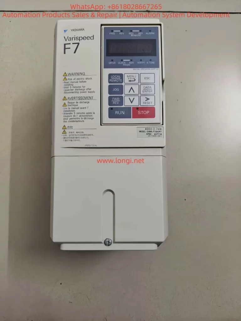
In Yaskawa’s Varispeed F7 series, the PG feedback card is not just an accessory—it is the core component that transforms the inverter from a standard open-loop V/f device into a high-performance vector drive. With accurate speed feedback, the F7 achieves servo-level control precision, excellent dynamic response, and high stability even under heavy load variations.
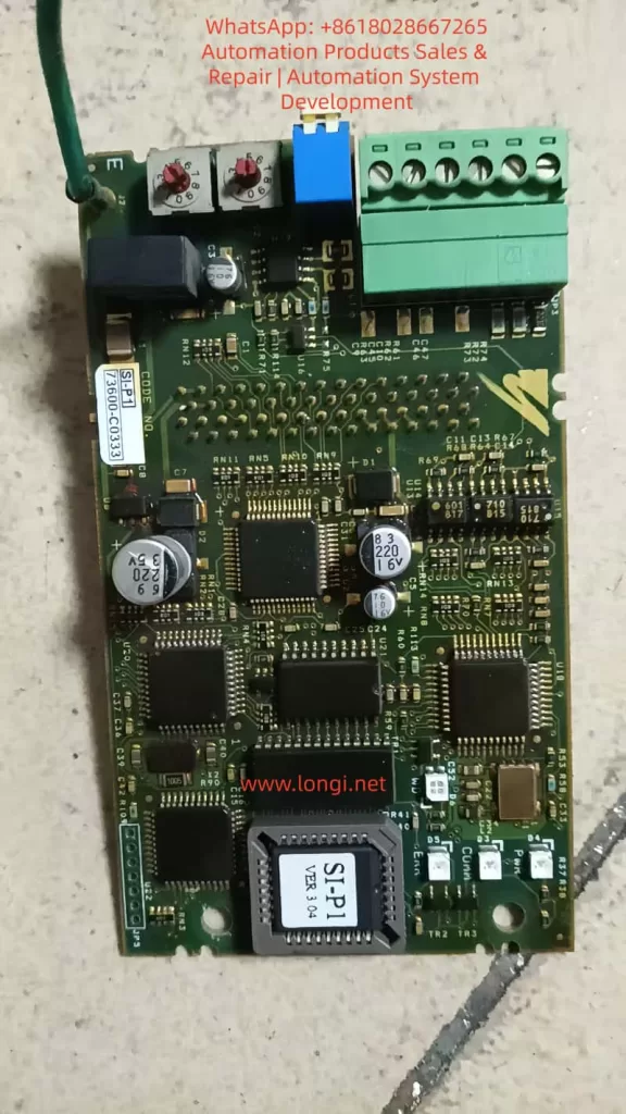
This paper focuses on the SI-P1 Ver 3.04 PG card (code 73600-C0333 / SIP-901), an OEM version widely used in the F7 family. By comparing it with the official PG-A2/B2/D2/X2 cards described in Yaskawa’s manuals, we analyze its structure, compatibility, wiring method, parameter configuration, and field performance in real industrial applications.
2. Technical Background — Function and Principle of PG Feedback
2.1 Basic Function of the PG Card
The PG card’s primary function is to receive incremental encoder signals (A, B, Z phases) and convert them into the internal pulse format that the inverter’s CPU can process. Based on these pulses, the inverter continuously calculates the rotational speed, direction, and position deviation of the motor.
This closed-loop feedback enables several advanced control modes:
Speed Feedback Control — maintains a precise target RPM regardless of load fluctuation.
Zero-Servo Control — holds the motor shaft at a fixed mechanical position.
Regenerative Braking Control — enhances braking torque using feedback phase information.
The accuracy and signal integrity of the PG card determine the overall response time, torque precision, and stability of the system.
2.2 Common PG Cards Used with the Varispeed F7
Model
Signal Type
Supply Voltage
Typical Application
Remarks
PG-A2
Differential TTL (A/A¯, B/B¯, Z/Z¯)
+5 V
Standard incremental encoders
Most widely used type
PG-B2
Open-collector (single-ended A/B)
+12 V
NPN output encoders
For environments with higher noise
PG-D2
Push-pull (A/B/Z quadrature)
+15 V
Heavy industrial, long-distance feedback
Excellent noise immunity
PG-X2
High-speed TTL differential
+5 V
High-resolution / high-speed vector control
Used in advanced servo applications
All four cards share the same mechanical interface and CN5 connector, but differ in electrical levels and signal types. Among them, PG-A2 is the standard type used in most F7 applications.
3. Identifying the SI-P1 Ver 3.04 and Its Compatibility
Although the SI-P1 Ver 3.04 is not explicitly listed in the official F7 manual, practical testing and circuit comparison confirm that:
The SI-P1 Ver 3.04 is an OEM-equivalent version of the PG-A2 card.
The justification is as follows:
Identical Signal Architecture The SI-P1 accepts differential inputs for A, /A, B, /B, Z, /Z, which perfectly matches the TTL line-driver interface of PG-A2.
Same Power Requirements It provides an internal +5 V DC output (maximum 200 mA) for encoder supply—exactly like the PG-A2—and does not support 12 V or 15 V encoders.
Same Physical Connector The card plugs directly into the F7 control PCB via the CN5 slot. Pin layout and dimensions are identical to the PG-A2.
Firmware Generation The “Ver 3.04” label corresponds to the firmware generation period of early-2000s Yaskawa F7 inverters, when PG-A2 was the default model.
Hence, the SI-P1 card can be treated as functionally identical to PG-A2. All wiring, parameter settings, and diagnostic methods described for PG-A2 apply equally to SI-P1.
4. Detailed Wiring between the SI-P1 and the Encoder
4.1 Terminal Definitions
Pin
Signal Name
Function
Description
1
+5 V
Encoder Power Supply
Provides +5 V DC (≤ 200 mA)
2
0 V
Power Ground
Common reference for encoder
3
A
Phase A positive
Forward rotation signal
4
/A
Phase A negative
Differential complement
5
B
Phase B positive
90° shift from A
6
/B
Phase B negative
Differential complement
7
Z
Zero-mark signal
Once-per-revolution pulse
8
/Z
Zero-mark complement
Optional connection
FG
Frame Ground
Connect to shield of cable
Use twisted-pair shielded cable for each differential pair (A/A¯, B/B¯, Z/Z¯). Connect the cable shield to FG at the inverter side only.
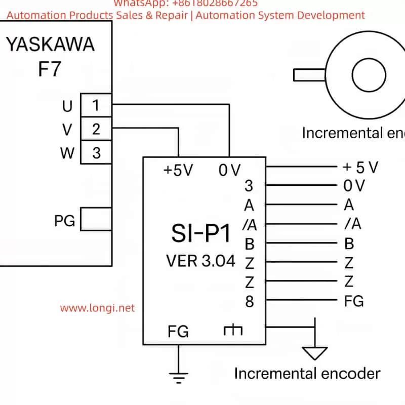
4.2 Typical Wiring Diagram
Encoder Side               SI-P1 PG Card
+5 V  ───────────────────────→  Pin 1 (+5 V)
0 V   ───────────────────────→  Pin 2 (0 V)
A    ───────────────────────→  Pin 3 (A)
A¯   ───────────────────────→  Pin 4 (/A)
B    ───────────────────────→  Pin 5 (B)
B¯   ───────────────────────→  Pin 6 (/B)
Z    ───────────────────────→  Pin 7 (Z)
Z¯   ───────────────────────→  Pin 8 (/Z)
Shield layer ─────────────→  FG (Ground)
This standard differential connection ensures noise immunity and reliable high-speed feedback, even under strong EMI conditions.
4.3 Electrical Precautions
Keep the encoder cable shorter than 20 m; for longer runs, use a differential line driver (RS-422 standard).
Never connect both ends of the shield to ground—do so only on the inverter side.
Verify the A/B phase shift (90° ± 10°) using an oscilloscope; reversed A/B causes inverted rotation detection.
Avoid running encoder cables in parallel with power cables.
5. Parameter Configuration and Commissioning
To enable the feedback loop, several parameters must be configured in the Varispeed F7:
Parameter
Description
Typical Setting
Notes
A1-02
Control Mode Selection
3
“Vector control with PG”
F1-01
Encoder Pulses per Revolution
e.g., 1024 PPR
Match actual encoder
F1-03
PG Input Type
0
Differential TTL input
E1-04
Rotation Direction Logic
0 or 1
Depends on wiring
U1-05
Monitor Speed Feedback
–
Used for verification
Commissioning Steps
Open-loop Test Run the inverter without enabling PG feedback. Verify that the motor runs smoothly and direction matches your system.
Enable Closed-Loop Mode Set A1-02 = 3 and cycle the power. The inverter now reads encoder feedback. Observe that the motor starts softly and maintains constant speed.
Zero-Servo or Position Hold For applications requiring shaft holding, fine-tune parameters F1-05 to F1-07.
Verification Check parameter U1-05 to ensure displayed speed matches the actual RPM measured by a tachometer.
6. Practical Field Experience and Case Studies
Case 1: Speed Feedback Optimization
A 37 kW Varispeed F7 inverter driving a conveyor motor used a 1024 PPR encoder. After replacing a damaged PG-A2 with an SI-P1 Ver 3.04, the system was configured with:
A1-02 = 3
F1-01 = 1024
F1-03 = 0
Result: Acceleration response improved from 100 ms to 40 ms, and steady-state speed fluctuation dropped below 0.3%. The SI-P1 performed identically to the original PG-A2.
Case 2: Direction Error due to Reversed Phases
In a hoisting control system, swapping A/B signal pairs caused the inverter to misinterpret rotation direction, leading to oscillation. After interchanging the A and B channels, feedback direction was corrected, and stability restored.
Case 3: Noise Interference and Shielding
A 15 m unshielded encoder cable caused ±5% speed variation due to EMI. Replacing it with twisted-pair shielded cable and grounding only at the inverter side reduced fluctuation to ±0.2%. Proper shielding proved critical for feedback reliability.
7. Signal Verification and Maintenance
Regular inspection of the PG system is essential for long-term stability.
7.1 Oscilloscope Test
Check A/B waveforms at the PG card input:
Duty cycle ≈ 50%
Phase shift ≈ 90° Distorted or noisy waveforms indicate cable damage or grounding issues.
7.2 Feedback Speed Monitoring
Under no-load constant-speed operation, monitor U1-05. If speed fluctuates, inspect PG connections, encoder bearings, and connector pins.
7.3 Cleaning and Care
The PG card contains sensitive CMOS components. Avoid dust or moisture. Clean contacts periodically with isopropyl alcohol and ensure firm seating in the CN5 slot.
8. Signal Mapping Comparison: SI-P1 vs PG-A2
Function
SI-P1 Pin
PG-A2 Pin
Remark
+5 V Supply
1
1
Encoder Power
0 V Ground
2
2
Common Ground
A Signal
3
3
Differential +
/A Signal
4
4
Differential –
B Signal
5
5
Differential +
/B Signal
6
6
Differential –
Z Signal
7
7
Zero Pulse
/Z Signal
8
8
Complement Zero
FG Shield
FG
FG
Cable Shield Ground
The one-to-one correspondence confirms that SI-P1 can replace PG-A2 without modification.
9. Engineering Discussion and Technical Insights
Functional Equivalence The SI-P1 Ver 3.04 is a fully compatible PG-A2 card, supporting all F7 feedback control modes including vector, torque, and zero-servo functions.
Signal Quality is Paramount Differential signal integrity and proper grounding are more critical than parameter tuning. Incorrect grounding can produce random “PG Loss” or “OV” faults.
Parameter Matching Always set the correct encoder PPR (F1-01) and direction logic (E1-04) to avoid instability or reverse torque.
Maintenance Importance Connector oxidation and vibration loosening are common causes of intermittent speed errors. Regular re-seating of the card ensures reliability.
Cost-Effective Substitution For legacy F7/G7 systems, the SI-P1 serves as an excellent, low-cost replacement for discontinued PG-A2 cards without any firmware or wiring change.
10. Conclusion
The Yaskawa Varispeed F7 remains one of the most reliable inverter platforms in industrial automation. As the key interface between the drive and the motor’s feedback device, the PG card is indispensable for achieving high-performance vector control.
Through detailed examination, this study confirms that SI-P1 Ver 3.04 is technically equivalent to the PG-A2 model. It shares the same wiring, electrical characteristics, and parameter settings. When properly connected and configured (A1-02 = 3), it enables full closed-loop operation with high accuracy and stability.
For field engineers, understanding this equivalence provides a major advantage—allowing quick replacement, reduced downtime, and seamless integration in maintenance or retrofit projects.
11. Summary of Best Practices
Always use shielded twisted-pair cable, one pair per differential channel.
Ground the shield at one end only (inverter side).
Verify A/B phase direction before enabling closed-loop mode.
Configure feedback parameters carefully according to the encoder specifications.
Periodically check the CN5 slot and card contacts for corrosion or dust.
By following these practices, the SI-P1 PG feedback system can deliver long-term precision and reliability comparable to servo-class control systems.
Author’s Note
This article is written as an original technical analysis for maintenance engineers, automation specialists, and industrial electronics technicians who maintain or retrofit Yaskawa Varispeed F7 inverters. It integrates both manual specifications and real-world experience gathered from field repairs and performance testing.
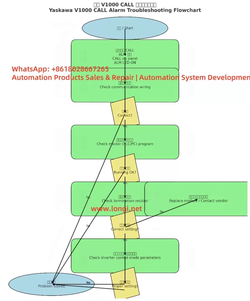
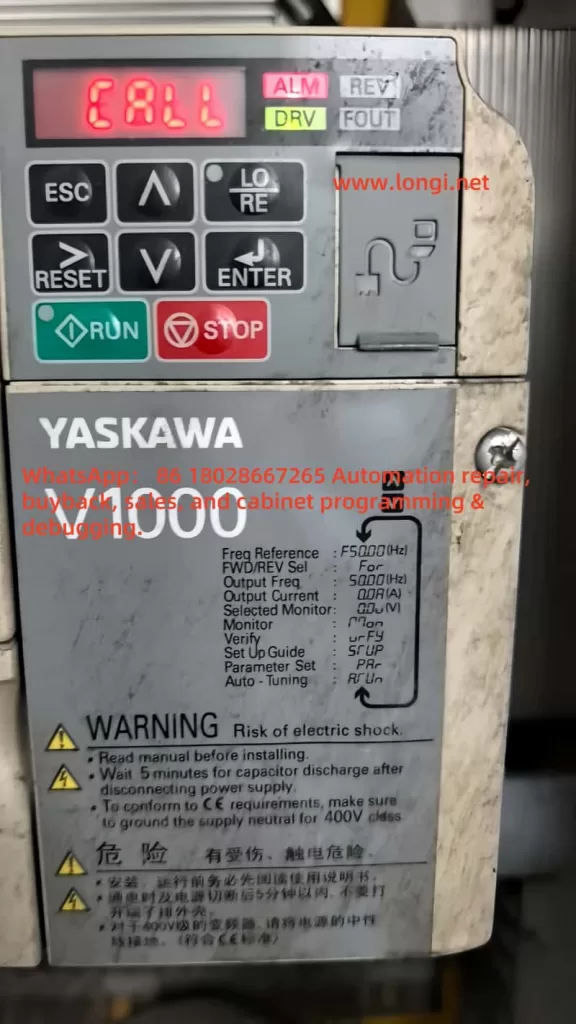
In modern industrial automation, inverters (VFDs) are not only used for motor speed control but also serve as vital communication nodes between field devices and PLCs or supervisory systems. The Yaskawa V1000 series, as a compact vector control inverter, is widely applied in conveyors, fans, pumps, compressors, and other equipment due to its stable performance and rich features. However, many engineers encounter a common issue during commissioning: Why can’t I find H5-01 or H5-02 communication parameters in the V1000 menu?
This article will provide a systematic explanation from the perspective of communication card hardware requirements, panel operation, step-by-step key procedures, and troubleshooting methods. After reading, you will fully understand how to access and correctly configure the H5 parameters on a V1000 inverter, enabling MEMOBUS (Modbus RTU) communication without confusion.
I. Communication Basics of the V1000 Inverter
1.1 Limitations of the Standard Model
The standard version of the V1000 does not include an RS-485 port by default. It only supports local operation through I/O terminals, such as start/stop signals and analog inputs. Therefore, if you search for H5-01 (slave address) or H5-02 (baud rate) in the parameter menu, you will not find the H5 parameter group.
1.2 Necessity of Expansion Cards
To enable communication, dedicated option cards must be installed, such as:
SI-485: RS-485 (Modbus RTU) communication card
SI-232: RS-232 communication card
Other fieldbus option cards: Profibus-DP, DeviceNet, CANopen, CC-Link, etc.
Once installed, the inverter automatically activates the relevant parameter group and displays H5-01, H5-02, and other settings.
1.3 Installation Position of Expansion Cards
Above the control terminal block of the V1000, there is a long pin connector slot designed for option cards. Installation requires:
Powering off and discharging the inverter to ensure safety.
Removing the front cover to expose the slot.
Inserting the communication card firmly into the slot and securing it with screws.
Re-powering the inverter, which will then detect the card and load the H5 parameter group.
II. Operation Panel Types and Differences
2.1 Standard LED Operator
Most V1000 units are equipped with a simplified LED operator panel, which includes the following buttons:
ESC (Exit/Back)
RESET (Fault reset)
↑/↓ (Parameter navigation or value adjustment)
ENTER (Confirm/Save)
RUN/STOP (Start/Stop motor)
Unlike larger inverters, this panel does not have a dedicated PRG key. To enter the parameter menu, you need to press and hold ESC for about 2 seconds instead of pressing PRG.
2.2 Advanced LCD Operator (Optional)
Some models may be equipped with an LCD operator panel, which provides more advanced displays and shortcut keys. Regardless of the panel type, the process of accessing H5 parameters is the same, with only minor differences in button usage.
III. Step-by-Step Procedure to Access H5 Parameters
The following example is based on the standard LED operator commonly found on the V1000.
Step 1: Enter Parameter Mode
After powering on, the display shows motor frequency, such as 0.00.
Press and hold the ESC key for 2 seconds to enter the parameter group selection mode.
The screen will display a parameter code, for example A1-01.
Step 2: Navigate to the H5 Parameter Group
Use the ↑/↓ keys to scroll through parameter groups.
You will see: A1-xx → b1-xx → C1-xx …
Continue scrolling until you find H5-01.
⚠️ Note: If the communication card is not installed or not recognized, the H5 parameter group will not appear.
Step 3: Configure H5-01 (Slave Address)
When H5-01 is displayed, press ENTER.
The screen switches to the current value, for example 01.
Use ↑/↓ to set the slave address (range 0 to FFH).
Press ENTER to save.
The screen briefly flashes, then returns to H5-01.
Step 4: Configure H5-02 (Baud Rate)
Press ESC to return to the parameter list.
Scroll to H5-02.
Press ENTER to view the current value, e.g., 03 (9600bps).
Use ↑/↓ to select the desired baud rate:
0 = 1200bps
3 = 9600bps
4 = 19200bps
8 = 115200bps
Press ENTER to save.
Step 5: Return to Monitoring Mode
Press ESC repeatedly until the display returns to the main frequency screen (e.g., 0.00).
The parameters are now set.
IV. Common H5 Configuration Examples
4.1 Single-Inverter Communication
H5-01 = 01 (slave address = 1)
H5-02 = 4 (baud rate = 19200bps)
Configure the PLC master with address 01 and baud rate 19200bps for communication.
4.2 Multi-Inverter Communication
Several V1000 inverters connected on the same RS-485 bus.
Each inverter must have a unique H5-01 value, e.g., 01, 02, 03.
All devices must share the same H5-02 baud rate, e.g., 19200bps.
Ensure termination resistors are enabled on both ends of the bus.
4.3 Commissioning Notes
A power cycle is required after parameter changes for them to take effect.
If communication fails, check baud rate and slave address consistency, and confirm R+/R- wiring polarity.
V. Common Issues and Solutions
5.1 H5 Parameters Missing
Cause: Communication card not installed, or wrong card type. Solution: Ensure SI-485 card is installed properly and compatible with V1000.
5.2 Parameter Changes Not Effective
Cause: Some parameters only apply after restart. Solution: Power off and restart the inverter after changes.
5.3 Communication Interruption
Cause: Long cable runs or strong EMI interference. Solution: Use shielded twisted pairs, ground the shield properly, and add termination resistors.
5.4 Panel Buttons Differ from Manual
Cause: Different operator versions (LED vs. LCD). Solution: For LED panels, press and hold ESC; for LCD versions, PRG may be available.
VI. Conclusion
This article systematically explained how to access and configure H5-01 and H5-02 parameters on the Yaskawa V1000 inverter. From hardware requirements (communication card installation) to operator panel differences and detailed step-by-step key operations, all potential problems have been clarified.
In short:
H5 parameters will not appear without a communication card.
On LED operators, hold ESC to enter parameter mode.
Always save changes and restart for them to take effect.
By mastering these procedures, engineers can easily configure V1000 inverters for Modbus RTU communication, ensuring seamless integration into automation systems.
In modern industrial automation systems, the inverter is the core device for motor control and energy-saving operations. It is widely used in pumps, fans, compressors, and various mechanical transmission systems. Among them, the Yaskawa V1000 inverter has become a popular choice due to its compact design, high reliability, and stable performance.
However, during field operation, many users encounter a situation where the inverter’s keypad displays “CALL”, while the ALM (alarm) indicator is lit. For beginners, this situation may seem confusing—“CALL” is often mistaken as a call instruction or program recall. In reality, it represents a communication-related warning.
This article will analyze the meaning of the CALL alarm, its possible causes, troubleshooting methods, and preventive measures, offering a structured guide to help engineers resolve this problem effectively.
2. Meaning of CALL Alarm
On Yaskawa V1000 inverters, CALL means “Communication Awaiting”.
When the inverter is set to communication control mode, it continuously waits for data from the master device (PLC, PC, or communication module).
If no valid data is received within a specific time, the inverter enters the CALL state.
In this case, the ALM LED turns on, indicating a minor fault (warning). Unlike a trip fault, it does not immediately stop the inverter but signals that communication has not been established correctly.
Therefore, CALL is not a severe error code, but a reminder that the communication link is inactive or faulty.
3. Main Causes of CALL Alarm
Based on Yaskawa’s official manual and field experience, the CALL warning is generally triggered by the following issues:
1. Incorrect communication wiring
Improper connection of RS-485 or MECHATROLINK cables, short circuits, loose connections, or broken wires will cause communication failure.
2. Master device program not running or faulty
If the PLC or PC is not transmitting communication commands, the inverter will always remain in the CALL state.
3. Communication circuit malfunction
Damaged communication modules, defective ports, or strong external interference may disrupt data transmission.
4. Improper termination resistor setting
In Modbus/MEMOBUS or MECHATROLINK systems, termination resistors must be installed at both ends of the communication line. Incorrect settings lead to unstable signals and communication errors.
5. Incorrect control mode settings
If the inverter is configured to communication mode (e.g., o2- parameters set to serial communication) but no master is connected, it will always display CALL.
4. Troubleshooting Steps
When the inverter shows CALL with ALM lit, the following step-by-step procedure is recommended:
Step 1. Check wiring
Verify RS-485 polarity (A/B terminals).
Ensure shielded twisted pair cables are used and grounded properly.
Inspect for loose, shorted, or broken wires.
Step 2. Check the master device
Confirm that the PLC or PC communication port is enabled.
Ensure that the master continuously transmits communication commands (e.g., Modbus function codes, MECHATROLINK frames).
Debug the ladder program to confirm proper command output.
Step 3. Check termination resistors
Install a 120Ω resistor at both ends of the communication line.
If the V1000 has an internal switch for termination resistance (e.g., S2 switch), ensure it is set to ON.
Step 4. Verify inverter parameters
Confirm o2- parameters (control mode selection).
If communication is not required → set the mode to panel or terminal control.
If communication is required → ensure correct baud rate, parity, and slave address settings.
Step 5. Power cycle test
After corrections, restart the inverter.
If CALL disappears, the issue is solved.
If it persists, consider replacing the keypad, communication module, or contacting Yaskawa technical support.
5. Case Studies
Case 1: Wiring error
A water pump system using PLC + V1000 in communication control showed CALL constantly. Upon inspection, RS-485 polarity was reversed. Correcting the wiring resolved the issue immediately.
Case 2: Master program inactive
In a production line upgrade, V1000 inverters were linked by Modbus. Since the PLC program had not been downloaded yet, all inverters displayed CALL. Once the master program was activated, the alarms cleared.
Case 3: Termination resistor missing
In a long-distance bus network, multiple V1000 units showed CALL alarms. Investigation revealed no termination resistors were installed. Adding 120Ω resistors at both ends solved the communication problem.
6. Preventive Measures
To avoid recurring CALL alarms, engineers should adopt the following best practices:
Standardized wiring
Always use shielded twisted pair cables.
Properly ground the shield layer to reduce interference.
Reliable master program
Ensure PLC/PC programs send communication frames immediately after startup.
Include heartbeat signals to prevent timeouts.
Correct termination resistor setup
Always place resistors at both ends of the communication line.
Verify onboard termination switch settings.
Control mode configuration
If communication is not required, set the inverter to terminal or panel control to prevent unnecessary CALL states.
If communication is required, confirm all protocol settings match between master and slave devices.
Regular maintenance
Periodically inspect cable connections and terminal blocks.
Check communication bus health in multi-inverter systems.
7. Conclusion
The CALL alarm on Yaskawa V1000 inverters is essentially a communication waiting warning, not a critical trip. It indicates that the inverter is not receiving valid data from the master device.
By systematically checking wiring, master device operation, termination resistors, and control parameters, engineers can quickly identify and resolve the issue. Moreover, if communication is not used, simply switching to panel or terminal control mode will prevent the CALL alarm.
Understanding CALL’s meaning and mastering troubleshooting procedures not only reduces downtime but also enhances the reliability of the overall automation system.
The Yaskawa V1000 series inverter is renowned for its efficient vector control performance and wide range of applications, making it a vital component in industrial automation, including systems like fans, pumps, and conveyor belts. However, during operation, the inverter may encounter various faults, with the “CALL” fault being a common communication-related issue. When the inverter’s display shows “CALL” accompanied by the ALM (alarm) light turning on, it typically indicates a communication link abnormality, which may result in system shutdown. This article provides an in-depth analysis of the nature of the “CALL” fault, its causes, and resolution methods, along with preventive measures to help users quickly restore equipment operation and enhance system reliability.
Nature of the “CALL” Fault
In the Yaskawa V1000 series inverter, “CALL” generally signifies a communication-related issue, potentially indicating that the inverter is awaiting a signal from a master device (e.g., PLC) or has detected an error in the communication link. In some instances, “CALL” may serve as a general prompt, urging users to investigate specific fault codes (e.g., “CE” for MEMOBUS/Modbus communication errors) further. The illumination of the ALM light suggests the inverter has detected an abnormal state, typically interrupting output and allowing the motor to enter a free-stop mode.
Based on relevant documentation, while “CALL” is not explicitly listed in the V1000 series fault code table, it is closely related to communication problems, possibly linked to codes like “CE” (MEMOBUS/Modbus communication error) or “bUS” (option card communication error). In certain communication protocols (e.g., Modbus), “CALL” might indicate a more severe communication issue, potentially necessitating inverter replacement.
Causes of the “CALL” Fault
The occurrence of a “CALL” fault may be attributed to the following causes:
Communication Cable Wiring Issues:
Loose, broken, or short-circuited communication cables can lead to data transmission failure.
Incorrect wiring (e.g., improper terminal connections) may prevent communication between the inverter and the master device.
Communication Parameter Configuration Errors:
Mismatched communication parameters (e.g., HS-01 slave address, HS-02 communication speed, HS-03 parity) with the master device.
For example, if the inverter’s baud rate is set to 9600 bps while the PLC is set to 19200 bps, communication will not establish.
Hardware Problems:
Failure or improper installation of communication option cards (e.g., Modbus, CC-Link, or PROFIBUS-DP cards).
Damaged or poorly contacted communication terminals.
Electromagnetic Interference (EMI):
Common electromagnetic noise in industrial environments (e.g., from motors or transformers) may disrupt communication signals, causing data transmission errors.
Master Station Program Errors:
Incorrect configuration in the master device (e.g., PLC) may prevent proper command transmission or response reception.
For instance, the PLC may not have the correct slave address or communication protocol set.
Communication Timeout:
If the inverter does not receive a response from the master within a specified time (e.g., as set by parameter HS-09), it may trigger a “CALL” fault.
Steps to Resolve the “CALL” Fault
To effectively address a “CALL” fault, follow these troubleshooting and resolution steps:
Step 1: Inspect Physical Connections and Wiring
Check Cables: Inspect communication cables for damage, breaks, or short circuits. Ensure the correct cable type (e.g., RS-485 or RS-422) is used.
Verify Connections: Confirm all terminals are securely connected with no looseness or poor contact.
Refer to Manual: Ensure terminal connections (e.g., R+, R-, S+, S-) are correct as per the Yaskawa V1000 technical manual.
Step 2: Verify Communication Parameters
Use the inverter’s digital operator panel or programming software (e.g., DriveWorksEZ) to check the following parameters:
HS-01 (Slave Address): Set to a unique address between 1-247, matching the master device.
The “CALL” fault is a significant communication-related issue in Yaskawa V1000 series inverters, potentially leading to system downtime and affecting production efficiency. By inspecting wiring, verifying communication parameters, performing self-diagnostic tests, and reducing electromagnetic interference, most “CALL” faults can be resolved. Implementing preventive measures such as regular maintenance, parameter documentation, and the use of shielded cables can greatly reduce the incidence of such faults. For complex or persistent issues, consulting the Yaskawa V1000 technical manual or contacting Yaskawa technical support for professional assistance is recommended. Ensuring the reliability of the communication system is crucial for maintaining stable operation in industrial applications.
The Yaskawa J1000 series inverters are widely used in industrial automation for their stable control performance and high energy efficiency. However, during actual operation, inverters may encounter various faults, one of which is the “Uu1” fault. This article will analyze the meaning, causes, and solutions for the Uu1 fault from both external and internal perspectives, providing a reference for inverter maintenance and repair.
I. Meaning and Causes of the Uu1 Fault
1. Fault Meaning
The Uu1 fault indicates an undervoltage output fault, meaning the inverter detects that the output voltage is below the set minimum value, triggering a protective mechanism. This fault often causes the inverter to stop, protecting the motor and load from potential damage.
2. Causes of the Fault
The Uu1 fault can be attributed to several factors:
Unstable power supply: The input voltage to the inverter is lower than the rated range, leading to insufficient output voltage.
Wiring issues: Poor contact in the input or output wiring causes voltage drops.
Internal inverter faults: Damage to the inverter’s internal circuits or components results in abnormal output voltage.
Motor or load faults: Issues with the motor or load cause abnormal feedback voltage.
3. On-Site Handling Methods
To address the Uu1 fault on-site, follow these steps:
Check the power supply voltage: Use a voltmeter to measure the inverter’s input voltage and ensure it is within the rated range. If the voltage is too low or unstable, inspect the power supply, and replace it or use a voltage stabilizer if necessary.
Inspect the wiring: Check the input and output wiring for proper contact, ensuring no loose or disconnected wires. If poor contact is found, reconnect the wiring and tighten the screws.
Examine the inverter internally: If the power supply and wiring are fine, the issue may lie within the inverter. Consult a professional technician or the manufacturer for repairs.
Check the motor and load: Ensure the motor is operating normally and inspect the load for any issues.
Reset the fault: After resolving the issue, press the RESET button on the inverter to clear the fault. Restart the inverter and observe its operation.
II. Analysis of Electrical Issues from the Inverter’s Internal Structure
1. Overview of the Inverter’s Internal Structure
The internal structure of the Yaskawa J1000 series inverter primarily includes the rectifier circuit, inverter circuit, control circuit, and protection circuit. The rectifier circuit converts AC voltage to DC voltage, the inverter circuit converts DC voltage to variable-frequency AC voltage, the control circuit regulates the output frequency and voltage, and the protection circuit detects and protects against faults such as overload, overvoltage, and overcurrent.
2. Electrical Issues Related to the Uu1 Fault
The Uu1 fault is typically associated with the inverter’s output circuit and involves the following aspects:
Rectifier circuit faults: Damage to diodes or capacitors in the rectifier circuit can lead to insufficient DC voltage, affecting the output voltage.
Inverter circuit faults: Damage to IGBT modules or driver circuits in the inverter circuit can cause abnormal output voltage.
Control circuit faults: Faults in the microprocessor or driver chips in the control circuit can result in inaccurate output voltage regulation.
Protection circuit faults: Malfunctioning detection components or protection chips in the protection circuit can lead to incorrect identification of undervoltage.
3. Electrical Repair Methods
To repair the Uu1 fault, follow these steps:
Inspect the rectifier circuit: Use a multimeter to test the diodes and capacitors in the rectifier circuit to ensure they are functioning correctly. Replace any damaged components.
Check the inverter circuit: Inspect the IGBT modules and driver circuits for proper operation. Replace any faulty modules or chips.
Examine the control circuit: Test the microprocessor and driver chips to ensure they are functioning correctly. Replace any faulty chips.
Inspect the protection circuit: Check the detection components and protection chips in the protection circuit for proper operation. Replace any faulty components.
III. Comprehensive Solutions for the Uu1 Fault
1. Preventive Measures
To prevent the occurrence of the Uu1 fault, consider the following measures:
Regularly check the power supply voltage: Periodically inspect the inverter’s input voltage to ensure stability.
Maintain wiring connections: Regularly check the wiring for proper contact and address any issues promptly.
Inspect the inverter internally: Periodically check the inverter’s internal circuits to identify and resolve potential faults early.
Maintain the motor and load: Regularly inspect the motor and load to ensure they are operating correctly.
2. Fault Handling Procedure
When addressing the Uu1 fault, follow this procedure:
Confirm the fault: Verify the Uu1 fault on the inverter’s display.
Check the power supply voltage: Ensure the input voltage is normal.
Inspect the wiring: Check for proper wiring connections.
Examine the inverter internally: Ensure the internal circuits are functioning correctly.
Check the motor and load: Verify that the motor and load are operating normally.
Reset the fault: After resolving the issue, reset the inverter and observe its operation.
3. Professional Support
If the Uu1 fault cannot be resolved through the above methods, consult a professional technician or the manufacturer for further assistance.
Conclusion
The Uu1 fault in the Yaskawa J1000 series inverters is a common undervoltage output fault with complex causes, involving the power supply, wiring, internal circuits, motor, and load. Through systematic fault analysis and step-by-step troubleshooting, the Uu1 fault can be effectively resolved, ensuring stable inverter operation. Regular maintenance and preventive measures are also crucial in avoiding such faults.