
Inovance HVD100E Series General-purpose Inverter User Guide: Operation Panel, Terminal Control and Fault Troubleshooting
The Inovance HVD100E series is a general-purpose variable frequency drive (VFD) designed for HVAC systems, municipal water supply and drainage, fans, pumps, and various industrial automation equipment. Operating on three-phase 380V-480V power, this series covers a power range from 0.7kW to 500kW across 12 chassis sizes (T1 through T12). With support for open-loop vector control (SVC), closed-loop vector control (FVC), V/f control, and PMVVC control, the HVD100E delivers versatile performance for applications requiring stable and reliable motor control. This comprehensive guide covers the LED operation panel, main circuit terminals, control terminals, parameter settings, RS485/Modbus communication, and extensive fault code troubleshooting to help users achieve optimal operation.
1. Product Overview and Specifications
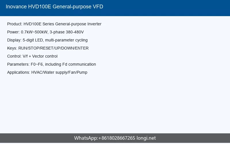
The HVD100E series inverter is engineered for general-purpose applications where reliability and adaptability are paramount. The product naming convention follows the format: HVD100E-4TxxP(B), where “4T” indicates three-phase 380-480V input, “xx” represents the power rating in kilowatts, “P” denotes light-duty overload capacity (110% for 60 seconds), and “B” optionally indicates built-in braking unit.
1.1 Key Technical Specifications
| Parameter | Specification |
|---|---|
| Input Voltage | Three-phase 380V-480V AC, 50/60Hz |
| Voltage Tolerance | -15% to +10% (323V-528V actual range) |
| Frequency Tolerance | ±5% (47.5Hz-63Hz actual range) |
| Output Voltage | Three-phase 0 to input voltage |
| Output Frequency Range | 0-599Hz (configurable via parameters) |
| Carrier Frequency | 0.8kHz-8.0kHz (T1-T9); 0.8kHz-6.0kHz (T10-T12) |
| Overload Capacity | 110% rated current for 60 seconds (light duty) |
| Control Methods | SVC, FVC, V/f control, PMVVC |
| Speed Control Range | 1:200 (SVC); 1:1000 (FVC) |
| Starting Torque | 0.25Hz/150% (SVC); 0Hz/180% (FVC) |
| Protection Rating | IP20 (T1-T9); IP00 (T10-T12) |
1.2 Product Variants by Chassis Size
| Chassis | Models | Power Range | Approx. Weight |
|---|---|---|---|
| T1 | 4T0.7PB to 4T3.7PB | 0.75-3.7 kW | 1.6-2.0 kg |
| T2 | 4T5.5PB to 4T7.5PB | 5.5-7.5 kW | 2.0 kg |
| T3 | 4T11PB to 4T15PB | 11-15 kW | 3.3 kg |
| T4 | 4T18.5PB | 18.5 kW | 4.3 kg |
| T5 | 4T22P to 4T30P | 22-30 kW | 7.6 kg |
| T6 | 4T37P to 4T45P | 37-45 kW | 17.5 kg |
| T7 | 4T55P to 4T75P | 55-75 kW | 35 kg |
| T8 | 4T90P to 4T132P | 90-132 kW | 51.5 kg |
| T9 | 4T160P to 4T200P | 160-200 kW | 85 kg |
| T10 | 4T220P to 4T280P | 220-280 kW | 110 kg |
| T11 | 4T315P to 4T355P | 315-355 kW | 155 kg |
| T12 | 4T400P to 4T500P | 400-500 kW | 185 kg |
2. LED Operation Panel
The HVD100E series features a comprehensive LED operation panel that serves as the primary human-machine interface for parameter configuration, status monitoring, and local control. Understanding the panel layout and functionality is essential for effective inverter operation and troubleshooting.
2.1 Panel Layout and Components
The LED operation panel measures approximately 116mm x 76mm with mounting dimensions of 104mm x 54mm. The panel is divided into functional zones including the display area, indicator lights, and control keys.
2.2 Panel Keys and Functions
| Key | Name | Function Description |
|---|---|---|
| PRG | Programming Key | Returns to the previous menu screen; enters first-level menu from main screen |
| ENTER | Confirm Key | Enters the next menu screen; confirms mode, parameter, and setting values |
| Up Arrow | Increment Key | Increases parameter numbers and setting values |
| Down Arrow | Decrement Key | Decreases parameter numbers and setting values |
| Left Arrow | Shift Key | Cycles through displayed parameters; shifts digit position during editing |
| RUN | Run Key | Starts inverter operation when in panel control mode |
| STOP/RES | Stop/Reset Key | Stops operation during running state; resets fault during alarm state |
| MF.K | Multi-function Key | Switches between preset functions based on F7-01 setting |
| QUICK | Quick Menu Key | Switches between different menu modes (configured via FP-03) |
2.3 Status Indicator Lights
The panel features multiple LED indicators that communicate the inverter’s operational state:
| Indicator | Name | Status Meanings |
|---|---|---|
| RUN | Run Indicator | Off: Stopped; On: Running |
| LOCAL/REMOT | Command Source Indicator | Off: Panel control; On: Terminal control; Flashing: Communication control |
| FWD/REV | Direction Indicator | Off: Forward running; On: Reverse running |
| TUNE/TC | Tuning/Torque Control/Fault Indicator | Off: Normal; On: Torque control mode; Slow flash (1Hz): Tuning; Fast flash (4Hz): Fault |
2.4 Display Area and Units
The 5-digit LED display shows parameter values, monitoring data, and fault codes. Unit indicators show Hz (frequency), A (current), V (voltage), RPM (speed), and % (percentage). The display can show set frequency, output frequency, various monitoring parameters, and alarm codes.
Special characters on the LED display correspond to specific letters: for example, “E” appears as the displayed character for fault codes (Err codes), and numerical digits display directly. Understanding this mapping is important for reading fault codes correctly when they appear.
2.5 Basic Panel Operations
To navigate the parameter menu: Press PRG to enter the menu structure, use the Up/Down keys to scroll through parameter groups (F0, F1, F2, etc.), press ENTER to enter a parameter group, scroll to the specific parameter number, press ENTER to view or edit the value, use Shift key to select the digit to modify, use Up/Down to change values, and press ENTER to confirm or PRG to cancel.
For quick parameter access, the QUICK menu key allows switching between different menu modes including basic parameters, changed parameters, and user-defined favorites, significantly speeding up commissioning and adjustment tasks.
3. Main Circuit Terminals
The main circuit terminals handle all power connections including AC input, DC bus, braking resistor, and motor output. Proper wiring and torque are critical for safe and reliable operation.
3.1 T1-T9 Terminal Configuration
For T1 through T9 chassis sizes, the main terminals are arranged as follows:
| Terminal Mark | Name | Function |
|---|---|---|
| R, S, T | Three-phase power input | Connect three-phase AC power supply |
| (+), (-) | DC bus positive, negative | Common DC bus connection point; external braking unit connection for T9+ |
| (+), BR | Braking resistor terminals | Braking resistor connection for T8 and below |
| U, V, W | Inverter output terminals | Connect three-phase motor |
| PE | Ground terminal | Protective earth connection |
3.2 T10-T12 Terminal Configuration
For T10 through T12 large chassis sizes, the terminal arrangement follows a similar pattern with higher current capacity terminals:
| Terminal Mark | Name | Function |
|---|---|---|
| R, S, T | Three-phase power input | Connect three-phase AC power supply |
| +, – | DC bus positive, negative | Common DC bus; external braking unit connection |
| U, V, W | Inverter output terminals | Connect three-phase motor |
| PE | Ground terminal | Protective earth connection |
3.3 Cable and Wiring Requirements
All power cables must be sized according to the inverter’s rated current with appropriate safety margins. Use the following guidelines:
- Input cables: Sized at 1.0-1.25 times rated input current
- Output motor cables: Sized at the motor rated current, considering harmonic heating effects
- Ground conductor: Minimum 50% of phase conductor cross-sectional area
- Shielded cables are recommended for motor connections, with proper 360-degree grounding
Tighten all terminal screws to the specified torque values. Insufficient torque causes overheating at connections; excessive torque damages threads or cracks terminal blocks.
4. Control Circuit Terminals
The control terminals provide the interface for command signals, analog references, status outputs, and communication. These terminals use low-voltage signals and require proper shielding and routing to avoid interference.
4.1 Control Terminal Functions
| Category | Terminal | Name | Function Description |
|---|---|---|---|
| Power Supply | +10V – GND | External +10V power | Provides +10V power, max 10mA. For external potentiometer (1kΩ-5kΩ) |
| +24V – COM | External +24V power | Provides +24V power, max 200mA. For DI/DO and sensors | |
| Analog Input | AI1 – GND | Analog input 1 | Input: DC -10V to +10V, impedance: 22kΩ |
| AI2 – GND | Analog input 2 | Input: -10V to +10V or 0-20mA (selected via J7 jumper) | |
| AI3 – GND | Analog input 3 | Input: -10V to +10V or 0-20mA (selected via J5 jumper). Supports PT100/PT1000 temperature sensors via F9-56 | |
| Digital Input | DI1 – COM | Digital input 1 | Opto-isolated, input frequency <100Hz. Valid level: 9V-30V |
| DI2 – COM | Digital input 2 | ||
| DI3 – COM | Digital input 3 | ||
| DI4 – COM | Digital input 4 | ||
| DI5 – COM | Digital input 5 / High-speed pulse | Also functions as high-speed pulse input up to 100kHz | |
| Analog Output | AO1 – GND | Analog output 1 | Voltage or current output (selected via J4 jumper). 0-10V or 0-20mA |
| AO2 – GND | Analog output 2 | Voltage or current output (selected via J6 jumper). 0-10V or 0-20mA | |
| Digital/Relay Output | DO1 – COM | Digital output 1 | Opto-isolated open-collector output. 0-24V, 0-50mA. Configurable as high-speed pulse output up to 100kHz |
| T/A1-T/B1, T/A1-T/C1, T/A2-T/C2 | Relay outputs | Contact rating: 250VAC 3A (cosφ=0.4); 30VDC 1A |
4.2 Jumper Configuration
Several jumpers on the control board configure input/output characteristics:
- J1: DI terminal power supply selection (internal +24V default or external)
- J4: AO1 output type selection (voltage default or current)
- J5: AI3 input type selection (voltage default or current)
- J6: AO2 output type selection (voltage default or current)
- J7: AI2 input type selection (voltage default or current)
- J9: AI2 current mode input impedance selection (500Ω or 250Ω)
4.3 Control Wiring Best Practices
When wiring control circuits, always use shielded twisted-pair cables. Ground the shield at the inverter end only using the provided shield grounding clamp for 360-degree bonding. Keep control cables separated from power cables by at least 200mm. If crossing is necessary, cross at 90-degree angles. Never run control cables in the same conduit as power cables.
5. Parameter Settings (F0-F6 Groups)
The HVD100E organizes parameters into functional groups. Understanding these groups is essential for proper configuration. This section covers the most important parameter groups for typical applications.
5.1 F0 Group – Basic Parameters
The F0 group contains the fundamental operating parameters that define the inverter’s basic behavior:
- F0-01: Motor control mode selection (0=V/f control, 1=SVC, 2=FVC, 3=PMVVC)
- F0-02: Command source selection (0=panel, 1=terminal, 2=communication)
- F0-03: Main frequency source selection (0=digital setting, 1=AI1, 2=AI2, 3=AI3, etc.)
- F0-07: Frequency resolution setting
- F0-10: Maximum output frequency (default 50.00Hz, up to 599Hz)
- F0-12: Upper limit frequency
- F0-13: Lower limit frequency
5.2 F1 Group – Motor Parameters
The F1 group stores motor nameplate data and tuned parameters:
- F1-00: Motor type selection (0=asynchronous, 1=synchronous PM)
- F1-01: Motor rated power
- F1-02: Motor rated voltage
- F1-03: Motor rated current
- F1-04: Motor rated frequency
- F1-05: Motor rated speed (RPM)
- F1-37: Auto-tuning command (0=no action, 1=static tuning, 2=dynamic tuning)
Correct motor parameter entry is essential for vector control performance. After entering nameplate data, perform auto-tuning (F1-37) to allow the inverter to measure actual motor characteristics.
5.3 F2 Group – Vector Control Parameters
The F2 group adjusts the performance of vector control algorithms:
- F2-00: Speed loop proportional gain
- F2-01: Speed loop integral time
- F2-03: Current loop proportional gain
- F2-04: Current loop integral gain
- F2-43: Inertia tuning and dynamic setting speed
5.4 F3 Group – V/f Control Parameters
When using V/f control mode, the F3 group configures the voltage-frequency relationship:
- F3-00: V/f curve selection (0=linear, 1=multi-point, 2=complete separation, 3=incomplete separation)
- F3-01: Manual torque boost (0.1%-30.0%)
- F3-18: Overcurrent stall action current (default 150%)
- F3-19: Overcurrent stall enable/disable
- F3-20: Overcurrent stall gain (default 20, range 0-100)
- F3-22: Overvoltage stall action voltage (default 770V, adjustable down to 700V)
- F3-23: Overvoltage stall enable/disable
- F3-24: Overvoltage stall gain (default 30-50 range)
- F3-26: Overvoltage maximum rising frequency (5-15Hz typical range)
5.5 F4 Group – Input/Output Terminal Parameters
The F4 group configures the digital input and output terminal functions:
- F4-00 to F4-04: DI1 through DI5 function selection (various functions: run, jog, reset, multi-speed, etc.)
- F4-41: DO1 output function selection (configurable as high-speed pulse output up to 100kHz)
- F4-10 to F4-12: Relay output 1 and 2 function selection
- F4-30 to F4-33: Analog input curve configuration
5.6 F5 Group – Running Parameters
The F5 group configures acceleration, deceleration, and running behavior:
- F5-00: Acceleration time 1 (range 0.0-6500.0 seconds)
- F5-01: Deceleration time 1
- F5-02: Acceleration time 2
- F5-03: Deceleration time 2
- F5-10: Acceleration/deceleration curve selection (0=linear, 1=S-curve)
5.7 F6 Group – Multi-function Parameters
The F6 group contains various advanced functions including jogging, DC braking, and skip frequencies:
- F6-00: Jog frequency setting (0.00-50.00Hz)
- F6-01: Jog acceleration time
- F6-02: Jog deceleration time
- F6-08: DC braking start frequency
- F6-09: DC braking time (0.0-36.0 seconds)
- F6-10: DC braking current (0.0%-100.0%)
6. RS485/Modbus Communication
The HVD100E provides standard RS485 communication capability supporting Modbus RTU protocol, enabling integration with PLCs, SCADA systems, and building automation networks.
6.1 Communication Hardware Interface
The RS485 interface is provided through terminal J13 (function expansion card interface) or through a dedicated RS485 communication card (MD38TX1 or MD38TX2 with isolation). Standard connections use terminals A (positive), B (negative), and GND (reference).
Important wiring requirements:
- Use twisted-pair shielded cable (minimum 0.5mm² cross-section)
- Maximum total network length: 1200 meters
- Maximum number of nodes: 31 (without repeaters) or 247 (with repeaters)
- Install 120Ω termination resistors at both ends of the bus
- Ground shield at one end only (typically the master/PLC end)
6.2 Modbus Protocol Configuration
The FD group parameters configure the communication settings:
| Parameter | Function | Typical Setting |
|---|---|---|
| Fd-00 | Local communication address | 1-247 |
| Fd-01 | Baud rate selection | 0=300bps, 1=600, 2=1200, 3=2400, 4=4800, 5=9600, 6=19200, 7=38400, 8=57600, 9=115200 |
| Fd-02 | Data format | 0=no parity/2 stop bits, 1=even/1 stop, 2=odd/1 stop, 3=no parity/1 stop |
| Fd-04 | Communication timeout setting | 0.0-60.0 seconds (0=disabled) |
6.3 Modbus Data Frame Structure
The HVD100E uses standard Modbus RTU data frames with the following structure:
- Slave Address (1 byte): Inverter station address (1-247)
- Function Code (1 byte): 03=Read holding registers, 06=Write single register, 10=Write multiple registers
- Data (N bytes): Register address and quantity, or data values
- CRC Check (2 bytes): Cyclic redundancy check for error detection
6.4 Parameter Address Mapping
Parameter addresses follow specific rules for Modbus access. Each parameter group has a defined address range, and both RAM (runtime) and EEPROM (storage) addresses are available. For example, F0 group parameters typically start at address 0x0000, F1 group at 0x0100, and so on. When writing parameters frequently during operation, use the corresponding RAM address to avoid excessive EEPROM write cycles.
The inverter status and monitoring parameters are accessible through dedicated addresses for real-time data such as output frequency, output current, DC bus voltage, and fault status.
6.5 Multi-bus Support
Beyond Modbus RTU, the HVD100E supports six industrial fieldbus protocols through optional communication cards: Profibus-DP, CANlink, CANopen, Profinet, EtherCAT, and Ethernet/IP. This multi-protocol capability allows seamless integration into virtually any industrial automation architecture.
7. Fault Codes and Troubleshooting (Err02-Err72)
The HVD100E provides comprehensive fault detection with detailed fault codes displayed on the LED panel. Understanding these codes and their remedies is essential for quick recovery from operational issues.
7.1 Overcurrent Faults (Err02-Err04)
Err02 – Acceleration Overcurrent (E02.00):
- Causes: Output short circuit or ground fault; FVC/SVC control without parameter tuning; acceleration time too short; excessive manual torque boost; starting into a spinning motor; external interference
- Remedies: Check motor and cable insulation; perform motor auto-tuning; increase acceleration time (F0-17); enable overcurrent stall (F3-19) and adjust action current (F3-18) to 120-160%; reduce torque boost or adjust V/f curve; use speed tracking restart or wait for motor stop; check for external interference sources
Err03 – Deceleration Overcurrent (E03.00):
- Causes: Output short circuit; deceleration time too short; overcurrent stall settings inappropriate; missing braking unit/resistor
- Remedies: Check motor insulation; increase deceleration time (F0-18); enable and adjust overcurrent stall parameters; install braking unit and resistor if regenerative energy is high
Err04 – Constant Speed Overcurrent (E04.00):
- Causes: Output short circuit; inverter undersized for application; overcurrent stall settings incorrect
- Remedies: Check motor and connections; verify inverter rating against actual load current; adjust stall prevention parameters; consider upsizing inverter if running continuously above rated current
7.2 Overvoltage Faults (Err05-Err07)
Err05 – Acceleration Overvoltage (E05.00):
- Causes: Input voltage too high; external force driving motor during acceleration; overvoltage suppression settings inappropriate; missing braking resistor
- Remedies: Verify input voltage within range; remove external driving force or install braking resistor; enable overvoltage suppression (F3-23) and adjust action voltage (F3-22) to 700-770V; increase acceleration time
Err06 – Deceleration Overvoltage (E06.00):
- Causes: Regenerative energy during deceleration exceeding dissipation capacity; deceleration time too short; missing braking components
- Remedies: Increase deceleration time; enable overvoltage suppression and adjust gain (F3-24); install or verify braking unit and resistor functionality
Err07 – Constant Speed Overvoltage (E07.00):
- Causes: External force driving motor during operation; overvoltage suppression settings incorrect
- Remedies: Remove external driving force or add braking resistor; adjust overvoltage suppression parameters (F3-22 through F3-26)
7.3 Power and Input Faults (Err08-Err09, Err12)
Err08 – Buffer Resistor Overload (E08.00):
- Causes: Input voltage outside specified range causing repeated contactor cycling
- Remedies: Verify and correct input voltage to within 323V-528V range; check for grid voltage instability
Err09 – Undervoltage Fault (E09.00):
- Causes: Momentary power loss; input voltage below specification; abnormal DC bus voltage; rectifier or control board fault
- Remedies: Enable momentary power loss ride-through (F9-59); verify input voltage; if DC bus voltage is abnormal, contact technical support
Err12 – Input Phase Loss (E12.00):
- Causes: Abnormal three-phase input power; incorrect wiring; drive board, surge protection board, or main control board fault
- Remedies: Check R-S-T wiring and three-phase voltage; verify no phase is grounded incorrectly; if internal fault suspected, contact technical support
7.4 Output and Motor Faults (Err10-Err11, Err13, Err19)
Err10 – Inverter Overload (E10.00):
- Causes: Motor protection parameter F9-01 setting inappropriate; load too heavy or motor stalled
- Remedies: Adjust F9-01 setting; reduce load and check mechanical conditions
Err11 – Motor Overload (E11.00):
- Causes: Motor protection parameter setting; excessive load or motor stall
- Remedies: Correct parameter settings; reduce load and inspect mechanical system
Err13 – Output Phase Loss (E13.00):
- Causes: Motor winding open; cable disconnection; unbalanced inverter output; IGBT module fault
- Remedies: Check motor continuity; inspect output cables and connections; verify motor windings; if IGBT suspected, contact technical support
Err19 – Motor Tuning Fault (E19.xx):
- Causes: Motor not connected; wrong motor parameters entered; output phase missing
- Remedies: Verify motor connections; enter correct nameplate data (F1-02 voltage, F1-03 current); ensure motor is unloaded for tuning; check and correct F2-29 for synchronous motor initial angle detection current
7.5 Temperature and Hardware Faults (Err14, Err18, Err21, Err23-Err24)
Err14 – Inverter Overtemperature (E14.00):
- Causes: Excessive ambient temperature; blocked air channels; damaged cooling fan; thermal sensor failure; module damage
- Remedies: Reduce ambient temperature; clean air channels and heatsinks; replace cooling fan; if thermal sensor or module suspected, contact technical support
Err18 – Current Detection Fault (E18.00):
- Causes: Current sampling circuit abnormal; Hall sensor damage
- Remedies: Verify main circuit is powered; if Hall sensor or sampling circuit damaged, contact manufacturer for control board replacement
Err21 – EEPROM Read/Write Fault (E21.xx):
- Causes: Writing to wrong parameter address; EEPROM chip damage
- Remedies: Verify using correct RAM addresses for frequent writes; if EEPROM chip damaged, replace control board
Err23 – Output Ground Short (E23.00):
- Causes: Motor or cable insulation breakdown to ground
- Remedies: Megger test motor and cables; replace faulty cable or motor
Err24 – Output Phase-to-Phase Short (E24.00):
- Causes: Two phases of U-V-W output shorted together
- Remedies: Inspect output cables and motor windings for short circuits
7.6 Communication and External Faults (Err15-Err16, Err20)
Err15 – External Device Fault (E15.01/E15.02):
- Causes: External fault signal received through DI terminals or virtual IO
- Remedies: Check external equipment; verify F8-18 restart permission; reset and restart
Err16 – Communication Fault (E16.xx):
- Causes: Modbus timeout (E16.01); CANopen timeout (E16.11); CANopen PDO mapping error (E16.12); CANlink heartbeat timeout (E16.21); CANlink station conflict (E16.22); Profibus-DP timeout (E16.41)
- Remedies: Check communication cable connections; verify Fd-04 timeout setting; verify baud rate and format settings match master; for CAN issues, check Fd-13 through Fd-17 parameters; resolve duplicate station addresses
Err20 – Encoder Fault (E20.xx):
- Causes: Encoder cable disconnected; wrong encoder line count setting (F1-27); wrong PG card wiring; broken encoder cable; Z signal missing
- Remedies: Check all encoder cable connections; verify F1-27 matches encoder specifications; confirm PG card power supply wiring; check encoder cable shielding; verify Z signal connection for synchronous motors
7.7 Application-Specific Faults (Err30-Err31, Err40, Err42-Err45, Err47-Err48)
Err30 – Load Loss (E30.00):
- Causes: Running current below F9-64 setting; mechanical load disconnected
- Remedies: Verify actual load conditions; adjust F9-64 and F9-65 parameters to match application
Err31 – PID Feedback Loss (E31.00):
- Causes: PID feedback signal below FA-26 threshold
- Remedies: Check feedback sensor and wiring; set FA-26 to appropriate value for application
Err40 – Cycle-by-Cycle Current Limit (E40.00):
- Causes: Excessive load or motor stall; inverter undersized
- Remedies: Reduce load; check mechanical system; upgrade to larger inverter if continuously overloaded
Err42 – Speed Deviation Excessive (E42.00):
- Causes: Incorrect encoder parameters; motor tuning not performed; detection parameters F9-69/F9-70 set improperly
- Remedies: Set correct encoder parameters; perform motor tuning; adjust detection parameters
Err43 – Motor Overspeed (E43.00):
- Causes: Similar to Err42 – encoder or tuning issues
- Remedies: Correct encoder parameters; perform motor tuning; adjust overspeed detection settings
Err45 – Motor Overtemperature (E45.00):
- Causes: Temperature sensor wiring loose; motor actually overheating; F9-57 protection threshold too low
- Remedies: Check temperature sensor connections; improve motor cooling; increase F9-57 threshold to 90-100°C for standard motors
Err47 – STO Fault (E47.00):
- Causes: STO terminals not receiving 24V when STO function enabled (F8-54)
- Remedies: Verify F8-54 setting; check 24V supply to STO terminals on inverter module
Err48 – Analog Input Wire Break (E48.01-E48.03):
- Causes: Enabled wire break detection for AI1/AI2/AI3 with actual broken wire condition
- Remedies: Check corresponding analog input wiring
7.8 Advanced and System Faults (Err60-Err64, Err66-Err71)
Err60 – Inverter Overheating Fault (E60.00): Internal temperature too high – replace internal cooling fan.
Err61 – Braking Transistor Overload (E61.00): Braking resistor resistance too low – replace with higher resistance braking resistor.
Err62 – Braking Transistor Short (E62.00): Braking unit malfunction – check braking transistor and verify external braking resistor configuration.
Err63 – Low Liquid Level (E63.00): For water-cooled systems – add cooling liquid.
Err64 – Water Cooling System Fault (E64.00): Water cooling control unit failure – reset or replace control unit.
Err66-71 (Water Pump Application Faults): These application-specific faults cover conditions like outlet low pressure, inlet water shortage, pipe burst, pressure sensor loss, outlet high pressure, and pump blockage. Each fault has specific parameter settings (A4 group) that define detection thresholds and response behavior. To suppress these faults when not using pump control functions, set the corresponding A4 group parameters to 0.
7.9 General Fault Recovery Procedures
When a fault occurs, the inverter stops output and displays the fault code. To recover:
- Record the fault code and any flashing digits (sub-codes provide additional detail)
- Identify and resolve the root cause using the troubleshooting tables above
- Press the STOP/RES (Reset) key on the panel to clear the fault
- If the fault was caused by an external condition that has been corrected, the inverter will return to standby
- Issue a new run command to restart operation
- For faults that cannot be cleared, or that recur immediately after clearing, investigate thoroughly before attempting restart
8. Commissioning and Basic Debugging
Following a structured commissioning procedure ensures safe and successful inverter startup.
8.1 Pre-power Checks
- Verify all wiring matches the wiring diagram – especially R/S/T input and U/V/W output
- Confirm grounding connections are secure and meet local codes
- Verify motor nameplate data (voltage, current, frequency, speed, power)
- Check that control terminals match the intended control scheme
- Ensure no tools or debris remain inside the inverter or cabinet
8.2 Basic Commissioning Steps
- Apply control power only and verify panel displays normally
- Restore factory defaults if needed (FP-01 = 1 for basic parameter initialization)
- Enter motor nameplate parameters in F1 group (F1-01 through F1-05 minimum)
- Set control mode in F0-01 (V/f for basic applications, SVC for better performance)
- Perform auto-tuning (F1-37 = 1 for static, 2 for dynamic if safe to rotate motor)
- Set command source (F0-02) and frequency source (F0-03) per application
- Set acceleration/deceleration times (F5-00 through F5-03)
- Set maximum and limit frequencies (F0-10, F0-12, F0-13)
- Configure input/output terminal functions (F4 group)
- Run at low speed first to verify motor rotation direction
- Gradually increase speed and verify current, voltage, and temperature readings
9. Routine Maintenance
Regular maintenance extends inverter life and prevents unexpected failures:
- Daily: Check cooling fans, ambient temperature, and abnormal noises
- Monthly: Clean air intake filters, check terminal tightness, inspect for discoloration
- Annually: Deep clean heatsinks, measure insulation resistance, verify protection functions, check capacitor condition if test equipment available
Expected component lifespans at 40°C ambient, 80% load, 24/7 operation: Cooling fans >=5 years; DC bus capacitors >=5 years. Replace cooling fans when noise increases or airflow decreases.
Conclusion
The Inovance HVD100E series general-purpose inverter offers a robust and versatile solution for motor control across a wide range of industrial applications. By mastering the LED operation panel, correctly wiring main and control circuits, properly configuring parameters, utilizing RS485/Modbus communication, and understanding fault codes, operators can achieve reliable and efficient system performance. For additional support, documentation updates, or spare parts, visit www.inovance.com or contact your local Inovance distributor.