
Posted on

Daikin Super Unit Manual Guide: Installation, Hydraulic Piping, Electrical Wiring, Filter, Regenerative Resistor, Pressure Sensor, Pump Replacement and Maintenance Diagnosis

Daikin Super Unit installation piping and wiring inspection

Daikin Super Unit Manual Guide: Installation, Hydraulic Piping, Electrical Wiring, Filter, Regenerative Resistor, Pressure Sensor, Pump Replacement and Maintenance Diagnosis

Why Installation and Maintenance Matter

Daikin Super Unit installation piping and wiring inspection

Many Daikin Super Unit faults do not come from the controller board itself. Common causes include poor cooling space, bad suction piping, weak grounding, incorrect filter wiring, pressure sensor cable vibration, hot regenerative resistor and missing calibration after pump replacement. This guide focuses on installation, wiring, maintenance and recalibration.

Mounting, Cooling and Fixing

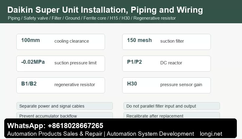
Leave sufficient cooling space around the controller and motor pump. The manual recommends at least 100 mm clearance. Do not block the motor cooling fan. The motor pump must be fixed firmly because hydraulic reaction force and startup shock can move it.

If the suction port direction is changed, follow the manual procedure. Do not hammer the pump shaft or force the port; damaged spline, shaft or seal surface will later cause noise, leakage, heat and reduced flow.

Hydraulic Piping

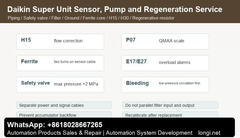
The Super Unit does not include a safety valve. Install one on the machine side and set it around maximum operating pressure plus 2 MPa. Avoid inappropriate straight check valves on the discharge side because they may prevent controlled pressure release. Accumulator circuits need backflow protection to prevent reverse pump rotation after power off.

Install a suction filter of about 150 mesh and keep suction pressure within -0.02 MPa. Low suction pressure causes air intake, cavitation noise, reduced flow and pressure pulsation.

Electrical Wiring

Main terminals include L1/L2/L3 power input, U/V/W motor output, P1/P2 DC reactor and B1/B2 regenerative resistor. Use correct wire size, crimp terminals and torque. Power cable and motor cable must never be connected to I/O terminals.

I/O terminals handle analog commands, monitor outputs, alarm contacts, digital I/O, pressure sensor and encoder signals. Keep analog and sensor cables away from U/V/W and contactor coils. Ground shields correctly.

Filter, Grounding and Noise Control

Use an input filter to suppress noise. The filter body must have good metal contact with the cabinet. Keep input and output cables separated; do not bundle them or route them in the same duct. Poor grounding or parallel filter wiring can cause random alarms, monitor noise and PLC input errors.

Regenerative Resistor and DC Reactor
Daikin Super Unit pressure sensor pump replacement and regeneration service

P1/P2 are used for the DC reactor. B1/B2 are used for the regenerative resistor. Regenerative energy appears during deceleration, load-driven rotation or hydraulic backflow. Install the resistor on a ventilated metal surface and prevent accidental touch. Wrong resistor value, capacity or wiring can lead to overvoltage or controller damage.

Pressure Sensor and H30

The pressure sensor is the core of pressure feedback. Install the ferrite core near the controller side of the sensor cable, around 100 mm from the terminal, with two turns. Fix the cable near the sensor so pump vibration does not pull the connector.

After replacing the pressure sensor, set H30 PS_G. Power up after pressure is released so zero point can be corrected, then calibrate with an accurate pressure gauge.

Pump Replacement, H15 and P07

After pump replacement, H15 Q_EV or P07 QMAX may need adjustment. Use monitor mode to observe Qo and compare with metering action, cylinder speed or measured flow. Do not blame parameters before checking suction pipe, filter, oil condition, leakage and valve resistance.

Preventive Service

Record oil temperature, noise, suction filter condition, fan status, Po/Qo monitor values, alarm history and high-pressure duty time. High oil temperature, dirty oil, suction leak and blocked filter often look like parameter problems but are hydraulic-condition problems.

Recommended delivery order: fixing and cooling, safety valve, suction pressure, filter grounding, main terminals, I/O analog signals, pressure sensor fixing, regenerative resistor cooling, low-pressure bleeding, PMAX/QMAX calibration, H30/H15 check and full-cycle machine test.
Posted on

Daikin SUT Injection Molding Machine Super Unit Manual Guide: Pi/Qi Pressure and Flow Commands, I/O Wiring, PMAX/QMAX, Response Parameters, Bleeding and Alarm Repair

Daikin SUT Super Unit Pi Qi pressure and flow control wiring

Daikin SUT Injection Molding Machine Super Unit Manual Guide: Pi/Qi Pressure and Flow Commands, I/O Wiring, PMAX/QMAX, Response Parameters, Bleeding and Alarm Repair

SUT Is a Servo Hydraulic Power Unit, Not a Simple Inverter Pump

Daikin SUT Super Unit Pi Qi pressure and flow control wiring

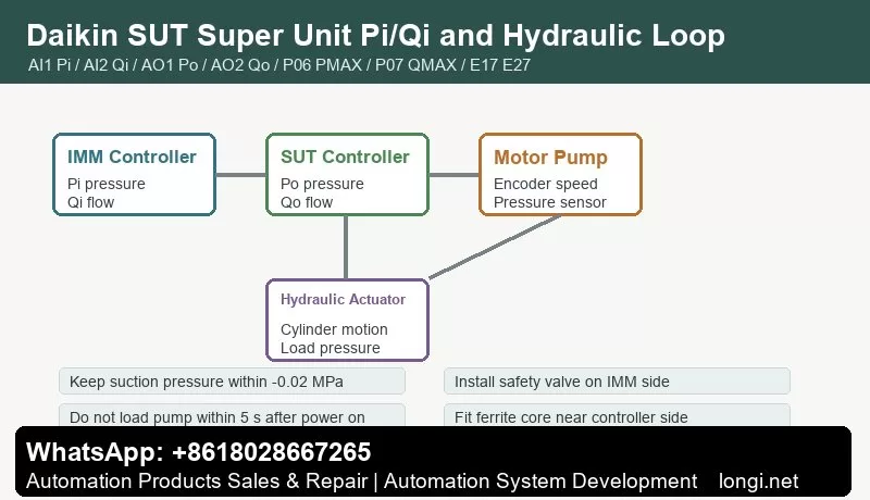
The Daikin SUT Super Unit for injection molding machines is a variable-speed IPM motor hydraulic system. The controller, motor pump, encoder, pressure sensor and machine hydraulic circuit form pressure and flow feedback loops. The injection molding controller sends analog command voltages; the SUT controls pump displacement Q by motor speed and controls pressure P by pressure sensor feedback.

For repair, do not treat it like a normal inverter pump. Check Pi pressure command, Qi flow command, Po pressure monitor, Qo flow monitor, pressure sensor, encoder, piping, oil condition, overload duty and valve timing together.

Matching Controller and Motor Pump

The manual states that the motor pump and controller are factory tested as a matched pair. Confirm serial numbers and model compatibility before replacement. When replacing the controller, pump or pressure sensor, check H15 flow correction, H30 pressure sensor gain and P07 QMAX. These values strongly affect actual hydraulic output.

Hydraulic Piping and Oil Conditions

The SUT does not include a safety valve. Install a safety valve on the injection molding machine side, normally set to maximum operating pressure plus 2 MPa. Use a suction filter of about 150 mesh and keep suction pressure within -0.02 MPa. Low suction pressure causes air intake and cavitation noise, with higher noise, reduced flow and possible pump damage.

After installation or repair, bleed the hydraulic circuit by moving each cylinder. Long high-pressure manual operation may cause E27 or E17 overload alarms; power off the controller to reset and continue under non-overload conditions.

Main Circuit and I/O Wiring

Main terminals include L1/L2/L3 power input, P1/P2 DC reactor, B1/B2 regenerative resistor and U/V/W motor output. Power, motor and signal wiring must not be mixed. Grounding must be reliable.

The I/O terminal block includes AI1 Pi pressure command, AI2 Qi flow command, AO1 Po pressure monitor, AO2 Qo flow monitor, AGND, pressure sensor signal and supply, ALM_A/ALM_B/ALM_C alarm output, DICOM/DOCOM and digital I/O. Separate analog ground, digital ground, shield and frame ground carefully.

The pressure sensor cable should use the specified connector. The ferrite core is fitted near the controller side, around 100 mm from the terminal, with two turns. Fix the cable near the sensor to prevent pump vibration from damaging the connector.

Pi/Qi and Po/Qo Linearity

Pi is pressure command voltage and Qi is flow command voltage, usually DC 0-10 V corresponding to 0-PMAX and 0-QMAX. Po and Qo are monitor outputs. Pi/Qi must be linear with the injection molding controller’s 0-99.9% pressure and flow settings. Otherwise the machine panel setting cannot accurately control hydraulic output.

If maximum analog voltage is below 10 V, set P05 VMAX and then calibrate PMAX/QMAX accordingly. During service, measure AI1/AI2 and AO1/AO2 at 20%, 50% and 80% settings.

Initial Parameters

Daikin SUT response parameters alarms and maintenance diagnosis

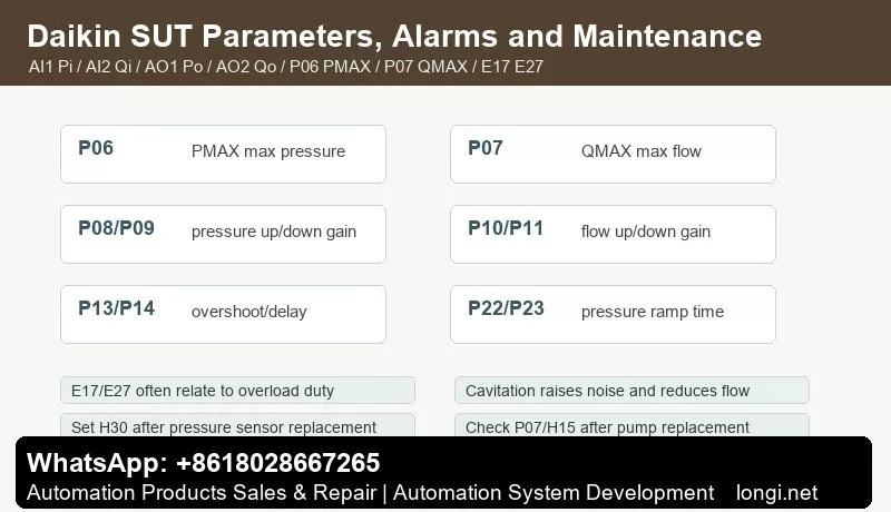
P06 is PMAX maximum control pressure. P07 is QMAX maximum discharge flow. The manual emphasizes that P06 and P07 must be set before operation. P07 is not theoretical pump displacement; it is a calibrated value based on actual pump speed and flow. P05 is the common command voltage scale for pressure and flow. WN_L is the overload warning output threshold.

If the same machine setting produces different speed or pressure after replacement, check P06, P07, P05, H15 and H30 before replacing hardware again.

Response Parameters

P08 P_UG adjusts pressure rise response. Higher value gives faster response but more overshoot. P09 P_DG adjusts pressure fall response. P10 and P11 adjust flow rise and fall response. P13 SC_G reduces pressure overshoot. P14 D_TM delays response from standby, allowing hydraulic valves to switch before the pump builds pressure.

P17-P21 are pressure proportional gain and integral time parameters. P22 and P23 set pressure rise/fall ramp time. Tune in this order: oil and piping first, Pi/Qi linearity second, P08-P11 basic response third, then P13/P14/P22/P23 for shock and overshoot control.

Startup and Bleeding

Do not load the pump within five seconds after power on. During bleeding, use manual low-risk operation and observe pressure, flow and noise. Crawling during injection unit movement may be caused by air in the circuit or pressure overshoot. Use moderate pressure and flow-control operation to verify stability.

Alarm Repair

E17/E27 overload alarms are often related to high pressure and high flow duty, long high-pressure manual bleeding, abnormal oil temperature, excessive load, fan trouble or poor cooling. Reduce duty, check oil temperature and cooling, then review aggressive response parameters.

Pressure sensor faults may come from open circuit, short circuit, incorrect wiring, abnormal pressure, poor connector contact or sensor failure. Check supply, signal, AGND, ferrite core and connector before replacing the sensor. After replacement, set H30 PS_G and calibrate with an accurate pressure gauge.

Low flow and loud noise usually point to suction pressure, suction filter, oil viscosity, oil temperature, suction leak or cavitation. Do not hide suction problems by increasing Q_UG or QMAX.

After pump replacement, check P07 QMAX and H15 Q_EV. In monitor mode, verify Qo and compare actual cylinder speed or metering flow.

Service Delivery Checklist

Before delivery, record P05, P06, P07, P08-P11, P13, P14, P16, P17-P23, WN_L, H15 and H30. Also record Pi/Qi, Po/Qo, current, oil temperature and alarm history during mold open/close, injection, holding, metering and ejection.

The reliable SUT repair sequence is: confirm pump-controller matching, check hydraulic piping and safety valve, verify I/O and analog linearity, set PMAX/QMAX, bleed the circuit, tune response parameters carefully and then diagnose overload, sensor or oil-circuit faults from alarm history.