
Inovance IS300 Series Servo Drive User Guide: Operation Panel, Position Control, Electronic Gear Ratio, CN1 Terminal Wiring and Fault Troubleshooting
The Inovance IS300 series servo drive is a high-performance vector-controlled servo drive specifically designed for driving permanent magnet synchronous motors (PMSM). It offers closed-loop vector control (VC) with high starting torque (180 percent at 0 Hz), wide speed regulation range (1:1000), and steady-state speed accuracy of plus or minus 0.02 percent. The IS300 supports both speed mode and position mode operation, making it suitable for injection molding machines, CNC machines, automated positioning systems, and general servo applications requiring precise motion control.
1. Operation Panel and Status Indicators
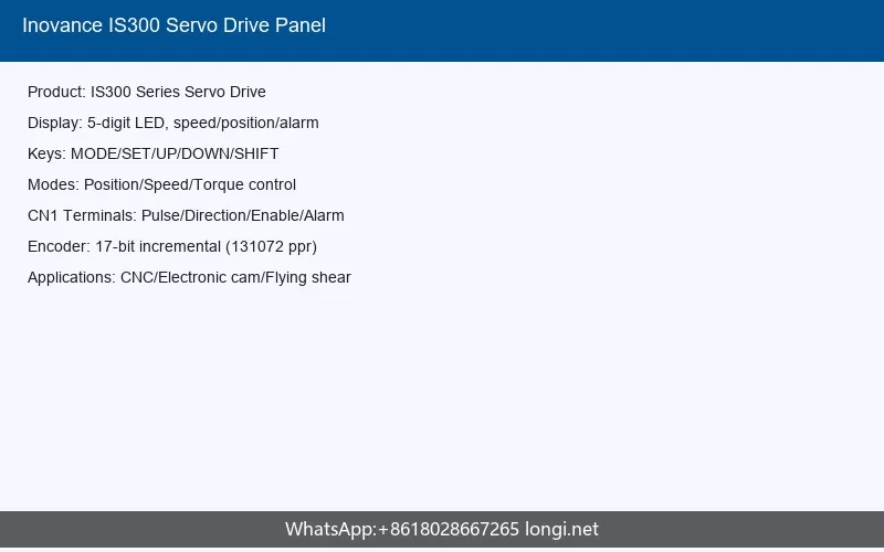
The IS300 servo drive features an integrated LED operation panel that can be either mounted directly on the drive or extended via an 8-core flat cable connected to the RJ45 interface. The panel provides real-time parameter access, monitoring, and control for commissioning and daily operation.
1.1 LED Display and Key Layout
The operation panel includes a 5-digit LED display capable of showing parameter codes, operational status, and alarm codes. The display uses a three-level menu structure for efficient navigation:
- Level I (Function Group): Selects parameter groups such as F0 (basic parameters), F1 (motor parameters), F2 (speed loop), F4 (DI/DO), F5 (relay output), and A3 (servo pump parameters).
- Level II (Function Code): Selects individual parameters within the chosen group.
- Level III (Parameter Value): Displays and allows modification of parameter values.
The panel keys and their functions are:
| Key | Name | Function |
|---|---|---|
| PRG | Programming Key | Enters and exits the Level I menu |
| ENTER | Confirm Key | Navigates into deeper menus and saves parameter changes |
| UP Arrow | Increment Key | Increases the value of the current digit |
| DOWN Arrow | Decrement Key | Decreases the value of the current digit |
| SHIFT | Shift Key | Selects which digit to modify; in monitoring mode, cycles through display parameters |
| RUN | Run Key | Starts motor operation in panel control mode |
| STOP/RES | Stop/Reset Key | Stops the motor; resets faults when in alarm state |
| QUICK | Quick Key | Enters quick-access menu for frequently used parameters |
| MF.K | Reserved | Reserved for future functions |
1.2 Status Indicators
The operation panel includes several LED status indicators that provide immediate visual feedback about the drive and motor state:
| Indicator | Status | Meaning |
|---|---|---|
| LOCAL/REMOT | Off | Panel control mode (keyboard start/stop) |
| On | Terminal control mode (DI input control) | |
| Blinking | Communication control mode (RS485 or CAN) | |
| RUN | On | Motor is running |
| Off | Motor is stopped | |
| FWD/REV | Off | Forward rotation |
| On | Reverse rotation | |
| TUNE/TC | On | Torque control mode |
| Slow blink | Auto-tuning in progress | |
| Fast blink | Fault state | |
| Hz | On | Frequency unit active |
| A | On | Current unit active |
| V | On | Voltage unit active |
| RPM | On | Speed unit active |
| % | On | Percentage unit active |
In the stopped state, pressing the SHIFT key cycles through parameters such as set frequency, AI1 voltage, AI2 voltage, AI3 voltage, and DC bus voltage. In the running state, it cycles through output frequency, output current, output voltage, motor speed, and AI input voltages.
1.3 Parameter Editing Workflow
Parameters are edited using the three-level menu. For example, to change parameter F0-04 from 0.00 Hz to 15.00 Hz:
- Press PRG to enter Level I menu. The display shows the function group.
- Use UP/DOWN to select group F0, then press ENTER.
- Use UP/DOWN to select function code F0-04, then press ENTER to enter Level III.
- Use SHIFT to select the digit to modify; use UP/DOWN to change the value to 15.00.
- Press ENTER to save and return to Level II; press PRG to save and automatically advance to the next parameter.
2. Position Mode Control with External Pulse Input
The IS300 servo drive supports position control mode for precise positioning applications. In position mode, the servo drive receives pulse commands from an external controller (such as a PLC, motion controller, or CNC system) through the CN1 control terminal. Each pulse corresponds to a specific angular displacement of the motor shaft, and the electronic gear ratio scales the pulse count to match the mechanical system requirements.
2.1 Control Circuit Terminal (CN1) Overview
The IS300 control board provides a comprehensive set of terminals via the control circuit connector. Key terminals for position control include:
| Category | Terminal | Function |
|---|---|---|
| Analog Input | AI1-GND | Analog input 1 (default: pressure command, range plus or minus 10V, 12-bit) |
| AI2-GND | Analog input 2 (default: flow command, range plus or minus 10V, 12-bit) | |
| AI3-GND | Analog input 3 (default: pressure sensor feedback, switchable between voltage and current) | |
| Digital Input | DI1-COM | Digital input 1 (programmable, default: run enable) |
| DI2-COM | Digital input 2 (programmable) | |
| DI3-COM | Digital input 3 (programmable) | |
| DI4-COM | Digital input 4 (programmable) | |
| DI5-COM | Digital input 5 (programmable) | |
| Analog Output | AO1-GND | Analog output 1 (programmable, voltage or current) |
| AO2-GND | Analog output 2 (programmable, voltage or current) | |
| Relay Output | T/A1-T/B1-T/C1 | Relay 1 (NC/COM/NO, programmable) |
| T/A2-T/C2 | Relay 2 (NO/COM, programmable) | |
| T/A3-T/C3 | Relay 3 (NO/COM, programmable) | |
| Communication | CANH/CANL/CGND | CAN bus communication (up to 1 Mbps) |
| 485A/485B | RS485 communication (up to 230 kbps) |
2.2 Pulse Input Configuration for Position Mode
To configure the IS300 for position control with external pulse input, the following parameter settings are required:
Step 1: Set control mode to non-pump mode (speed/position mode)
Step 2: Set command source
F0-03 = 9 (Communication given frequency, used for pulse-position mapping)
Step 3: Configure DI terminals for position control functions
F4-01 = 48 (DI2: Servo pump PID selection terminal 1)
F4-02 = 53 (DI3: Slave pump address selection terminal 1)
F4-03 = 9 (DI4: Fault reset)
F4-04 = 50 (DI5: CAN communication enable)
The pulse input signals are typically connected to the appropriate DI terminals or through the communication interface. For direct pulse input, the drive receives pulse and direction signals that are processed by the internal position loop to control motor movement.
2.3 CN1 Terminal Wiring for Pulse and Direction Signals
For position control applications using external pulse commands, the wiring must ensure clean signal transmission. The general wiring guidelines for the IS300 control terminals are:
Digital Input Wiring (NPN/Sink Type – Most Common):
The IS300 digital inputs support both NPN (sink) and PNP (source) configurations. The default internal 24V power supply can be used, or an external power supply can be connected.
+24V (internal) — shorted to OP (default)
COM — common return
Controller NPN output — DI terminal (DI1~DI5)
Controller common — COM
When using an external power supply, remove the shorting jumper between +24V and OP. Connect the external 24V positive to OP, and route the external 0V through the controller contacts to the DI terminals.
Important Wiring Rules:
- Use shielded cables for all control signals, keeping cable lengths under 20 meters.
- Separate control signal cables from power cables (R, S, T, U, V, W) by at least 30 centimeters.
- When connecting multiple drives in parallel, do not directly parallel the DI terminals without isolation diodes (IF greater than 10 mA, UF less than 1V).
- Ground the shield at one end to prevent ground loops.
3. Electronic Gear Ratio Calculation and Fixed-Length Positioning Example
3.1 Electronic Gear Ratio Formula
The electronic gear ratio is a fundamental parameter in servo positioning systems. It defines the scaling relationship between the command pulse count from the controller and the actual motor rotation. The gear ratio ensures that the mechanical movement matches the controller’s pulse output.
The general formula for electronic gear ratio is:
Or expressed as a ratio:
Where:
- Encoder Resolution: The number of pulses the encoder outputs per motor revolution (e.g., 10000, 2500, or 1000 lines with quadrature encoding).
- Load Movement per Motor Rev: The linear displacement of the mechanical load for each full motor rotation (e.g., 10 mm for a 10 mm pitch ball screw).
- Command Pulse Unit: The desired displacement per command pulse (e.g., 1 pulse = 1 micrometer, or 1 pulse = 0.01 mm).
3.2 Practical Fixed-Length Positioning Example
Consider a linear positioning system with the following specifications:
- Target movement: 100 mm
- Ball screw pitch: 10 mm per revolution (1 rev = 10 mm travel)
- Encoder resolution: 10000 pulses per revolution (using 2500-line encoder with 4x quadrature)
- Desired command resolution: 1 micrometer per pulse (0.001 mm/pulse)
Step 1: Calculate required motor revolutions
Motor Revs = 100 mm / 10 mm per rev = 10 revolutions
Step 2: Calculate encoder pulses for target movement
Encoder Pulses = 10 x 10000 = 100,000 pulses
Step 3: Calculate required command pulses
Command Pulses = 100 mm / 0.001 mm = 100,000 pulses
Step 4: Determine electronic gear ratio
Gear Ratio = 100,000 / 100,000 = 1:1
Therefore, set:
Numerator (B) = 1
Denominator (A) = 1
Alternative Example with Different Resolution:
If the desired command resolution is 10 micrometers per pulse (0.01 mm/pulse) for the same 100 mm movement:
Gear Ratio = 100,000 / 10,000 = 10:1
Set Numerator (B) = 10
Set Denominator (A) = 1
On the IS300, the electronic gear ratio parameters are configured through the position control parameter group. The gear ratio determines how many motor encoder pulses correspond to each command pulse from the external controller.
Motor Revs = D / P
Required Encoder Pulses = Motor Revs x E
Command Pulses = D / C
Gear Ratio = (D x E / P) / (D / C) = (E x C) / P
For 10000 ppr encoder, 10 mm pitch, 1 um/pulse command: Ratio = (10000 x 0.001) / 10 = 1:1
3.3 Parameter Settings for Position Control
After calculating the electronic gear ratio, configure the following IS300 parameters:
| Parameter | Value | Description |
|---|---|---|
| F0-01 | 1 | Vector control mode (VC) |
| F0-02 | 1 | Terminal command source |
| F0-03 | 9 | Communication given frequency |
| F0-17 | 0.0 s | Acceleration time (set to 0 for position mode) |
| F0-18 | 0.0 s | Deceleration time (set to 0 for position mode) |
| F1-00 | 2 | Motor type: Permanent magnet synchronous motor |
| F4-00 | 1 | DI1: Run enable (Servo ON) |
| F4-03 | 9 | DI4: Fault reset |
| F5-01 | 2 | Fault output relay |
4. Fault Codes and Troubleshooting Solutions
The IS300 servo drive provides comprehensive fault detection and protection. When a fault occurs, the drive stops output, the fault relay activates, and the fault code is displayed on the LED panel. The following table lists the most common fault codes and their solutions:
4.1 Overcurrent Faults (Err02, Err03, Err04)
| Fault Code | Name | Possible Causes | Solutions |
|---|---|---|---|
| Err02 | Acceleration Overcurrent | Short circuit in output; motor parameter tuning not performed; acceleration time too short; sudden load change during acceleration | Check U/V/W wiring for shorts; perform motor auto-tuning (F1-16); increase acceleration time; remove sudden load changes; verify input voltage is within range |
| Err03 | Deceleration Overcurrent | Output short circuit; deceleration time too short; sudden load addition during deceleration; missing braking unit/resistor | Check output wiring; perform motor tuning; increase deceleration time; add braking resistor and braking unit if needed |
| Err04 | Constant Speed Overcurrent | Output short circuit or leakage; motor tuning not performed; sudden load addition; motor blocked | Check output wiring and add output reactor if cable is long; perform motor tuning; remove sudden load; reduce load or use larger capacity drive |
4.2 Overvoltage and Undervoltage Faults (Err05, Err06, Err07, Err09)
| Fault Code | Name | Possible Causes | Solutions |
|---|---|---|---|
| Err05 | Acceleration Overvoltage | Input voltage too high; external force driving motor during acceleration; acceleration time too short; missing braking unit | Adjust input voltage to normal range; eliminate external force or add braking resistor; increase acceleration time; install braking unit and resistor |
| Err06 | Deceleration Overvoltage | Input voltage too high; external force during deceleration; deceleration time too short; missing braking resistor | Adjust input voltage; remove external force or add braking resistor; increase deceleration time; install braking resistor |
| Err07 | Constant Speed Overvoltage | Input voltage too high; external force driving motor during operation | Adjust input voltage; eliminate external force or add braking resistor |
| Err09 | Undervoltage | Input voltage too low; momentary power failure; abnormal DC bus voltage; damaged rectifier bridge or buffer resistor | Check input voltage specification (220V or 380V range); verify rectifier bridge and buffer resistor; replace damaged components; check drive board and main control board |
4.3 Motor and Drive Protection Faults (Err10, Err11, Err12, Err13, Err14, Err15)
| Fault Code | Name | Possible Causes | Solutions |
|---|---|---|---|
| Err10 | Drive Overload | Excessive load; motor blocked; drive capacity too small | Reduce load; check motor and mechanical system; use larger capacity drive |
| Err11 | Motor Overload | Motor protection parameter (F9-01) set improperly; excessive load; motor blocked | Adjust motor protection parameter appropriately; reduce load; check motor and mechanical system |
| Err12 | Input Phase Loss | Abnormal three-phase input power; damaged drive board; damaged main control board | Check three-phase input power; replace drive board or main control board |
| Err13 | Output Phase Loss | Faulty wiring between drive and motor; unbalanced output without motor; damaged drive board; damaged power module | Check power leads to motor; verify output balance without motor; replace drive board or power module |
| Err14 | Module Overheating | High ambient temperature; blocked air duct; damaged cooling fan; damaged thermistor; damaged inverter module | Reduce ambient temperature; clean air duct; replace cooling fan; replace thermistor; replace inverter module |
| Err15 | External Device Fault | External fault signal input through DI terminal; STOP key pressed in non-keyboard mode | Check and eliminate external fault source; check DI terminal wiring; use STOP key only in keyboard mode |
4.4 Encoder and Communication Faults (Err16, Err42, Err43, Err44)
| Fault Code | Name | Possible Causes | Solutions |
|---|---|---|---|
| Err16 | Modbus Communication Fault | Host computer not working; faulty RS485 wiring; incorrect communication parameters | Check host computer; verify RS485 wiring; set correct communication parameters (baud rate, data format, address, timeout) |
| Err42 | CAN Communication Fault | Incorrect CAN parameters; poor CAN wiring contact; CAN+/CAN- reversed; non-standard CAN cable | Set correct CAN parameters (A2-00, A2-01); fix wiring; ensure CAN cable is twisted-pair shielded and within length limits |
| Err43 | Resolver Encoder Tuning Fault | Encoder type mismatch; encoder wiring error; encoder installation error; damaged PG card | Select matching encoder; verify encoder wiring; reinstall encoder correctly; replace PG card |
| Err44 | Speed Deviation Excessive | Loose encoder wiring or installation; loose motor power cables; damaged PG card | Secure encoder wiring and installation; tighten motor power cables; replace PG card |
4.5 Additional Important Fault Codes
| Fault Code | Name | Quick Solution |
|---|---|---|
| Err18 | Current Detection Fault | Check Hall devices; replace drive board |
| Err19 | Motor Tuning Fault | Verify motor parameters match nameplate; check wiring; ensure tuning process completes within timeout |
| Err20 | Encoder (Code Disc) Fault | Check encoder model match; verify wiring; reinstall encoder; replace PG card |
| Err21 | EEPROM Read/Write Fault | Replace main control board |
| Err23 | Ground Short Circuit | Check motor ground short; replace cable or motor; replace drive if internal fault |
| Err40 | Wave-by-Wave Current Limit | Check output for shorts; perform motor tuning; increase accel/decel time; add braking resistor |
| Err45 | Motor Overheat | Check motor temperature; verify thermal protection wiring; reduce load; improve cooling |
| Err46 | Oil Pressure Sensor Fault | Check pressure sensor wiring; verify sensor power supply; replace sensor |
| Err49 | Resolver PG Disconnection | Check resolver wiring; verify resolver excitation signals; replace resolver or PG card |
| Err58 | Parameter Restore Error | Re-attempt parameter restore; replace main control board if persistent |
4.6 Fault Reset Procedures
To reset a fault on the IS300:
- Panel Reset: Press the STOP/RES key when a fault is displayed. The fault will be cleared if the cause has been resolved.
- Terminal Reset: Configure a DI terminal as fault reset (function 9) and activate it briefly.
- Power Cycle: Turn off power, wait for the CHARGE indicator to extinguish, then turn power back on.
For faults like Err08 (buffer resistor fault), the fault is non-resettable and requires service contact. Similarly, encoder-related faults (Err20, Err43) may require re-tuning or hardware replacement.
5. Maintenance and Daily Care
Regular maintenance ensures long-term reliability of the IS300 servo drive:
- Daily: Check for abnormal motor noise or vibration; verify cooling fan operation; check for overheating; keep the drive clean and free of dust, especially metal dust.
- Periodic: Clean air ducts; check and tighten screws; inspect terminals for arc marks; perform insulation testing (disconnect drive first; use 500V megohmmeter).
- Component Replacement: Cooling fans typically last 2-3 years; electrolytic capacitors last 4-5 years under normal conditions. Replace when abnormal noise, vibration, or leakage is detected.
The IS300 is backed by an 18-month warranty from the factory date. For technical support, contact Inovance service at 4000-300124 or 400-777-1260.