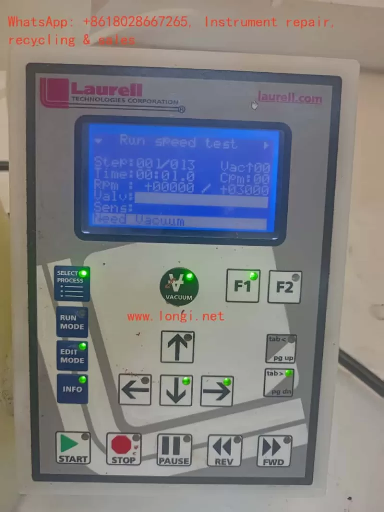
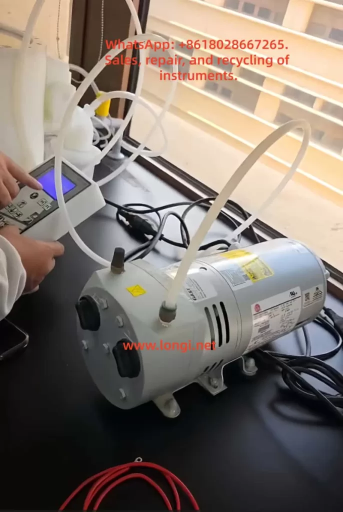
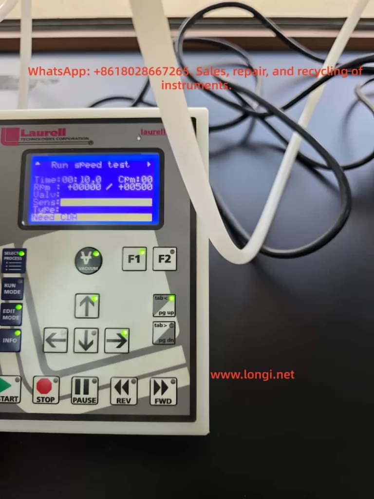
In the field of spin coating processes, operators often encounter a seemingly contradictory fault phenomenon: the equipment powers on normally, the program interface can be accessed, and after pressing the vacuum button, the external vacuum pump seems to be working (as indicated by the sound it makes), but the substrate cannot be firmly adhered, preventing the equipment from entering a stable operating state. Sometimes, messages like “Need CDA” or “Need Vacuum” even appear on the screen. Many users immediately attribute the fault to a “broken vacuum pump” and proceed to replace or disassemble it for inspection, only to find that the issue remains unresolved after much effort. In fact, for Laurell WS-650 spin coaters, the root cause of such faults often does not lie in the vacuum pump itself but rather in a failure of one of the components within the vacuum retention, pneumatic control, sealing interlock, and sample clamping systems.
This type of problem is prone to misdiagnosis because many people focus solely on “whether there is a sound” and overlook the fact that the vacuum system of a spin coater is not merely a “pump + suction cup” structure. It actually comprises multiple parts, including an external vacuum source, pneumatic vacuum valves, sealing purge gas sources, vacuum piping, fixtures, O-rings, sample coverage area, control interlock logic, and vacuum feedback detection. Any deviation in any of these components can result in the phenomenon of “the pump making a sound but the sample not adhering.” For engineers, equipment managers, and third-party maintenance personnel, only by adopting a system-level approach to understand the vacuum retention logic of the Laurell WS-650 can they quickly and accurately locate the fault, avoiding ineffective disassembly and incorrect part replacements.
1. Why “Hearing the Pump Make a Sound” Does Not Equate to a Normal Vacuum System
In industrial equipment maintenance, a common misconception is to equate “having an action” with “normal functionality.” For example, just because a contactor closes does not mean the main circuit is necessarily conducting; just because a fan is running does not mean the air pressure is sufficient; similarly, just because the vacuum pump makes a sound does not mean that the substrate clamping vacuum in the spin coater has been truly established.
The vacuum retention in a Laurell WS-650 does not simply involve the pump starting up and immediately adhering the substrate. Several conditions must be met simultaneously: First, the external vacuum source must provide sufficient negative pressure; second, the controller must allow the pneumatic vacuum valve to open; third, the vacuum channel must be well-sealed with no leaks; fourth, the sample must correctly cover the O-ring to form an effective sealing surface; fifth, the vacuum detection value must meet the interlock requirements. In other words, the vacuum pump is merely one of the “sources” in the entire system and should not be the sole basis for fault judgment.
If the external pump is running but the pneumatic vacuum valve does not open, the negative pressure will not reach the chuck surface. Even if the valve opens, if the sample does not cover the O-ring, the system will continuously leak air. If the O-ring is aged, contaminated with glue, or installed in the wrong position, continuous leakage will also occur. If the vacuum path has been contaminated with chemical liquids, the valve spool may become sticky and jammed, resulting in the pump working at the rear end but no effective adsorption force at the front end. Therefore, when facing such faults, maintenance personnel should not停留在 (remain stuck at) the superficial judgment of “whether the pump is making a sound” but should focus on the core issue of “whether the negative pressure truly reaches the chuck surface and forms stable retention.”
2. Working Principle of the Laurell WS-650 Vacuum System
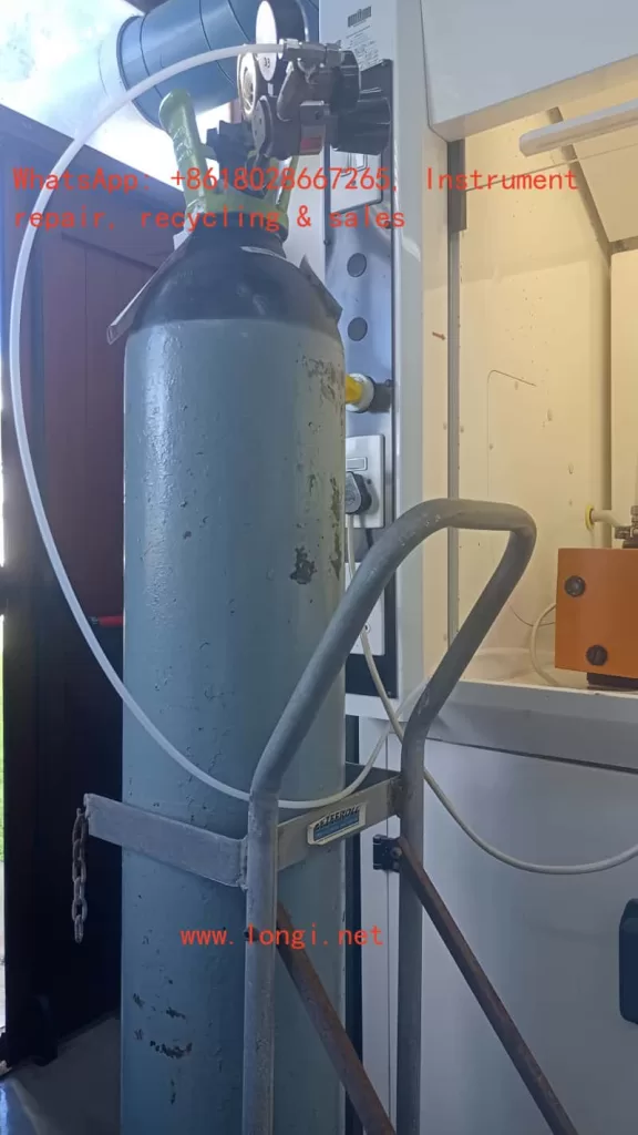
To truly understand this fault, it is essential to first grasp the vacuum control structure of the Laurell WS-650. The vacuum retention function of this model is not fully electrically driven but incorporates a certain pneumatic control logic. Simply put, the external vacuum source is responsible for providing negative pressure, and the internal vacuum valves of the equipment determine whether this negative pressure is introduced to the chuck. The action of these valves is related to other interlock conditions of the equipment, with the most typical being the sealing purge gas from CDA (Clean Dry Air) or N2.
Many users do not realize the direct causal relationship between the “Need CDA” message on the screen and the “vacuum not adhering” issue. In fact, CDA or N2 is not just an auxiliary gas source; it is also related to the internal sealing purge and some interlock actions of the equipment. As long as there is a lack of this gas source, insufficient pressure, or incorrect connection, the equipment may not allow the vacuum valve to operate normally or may determine in its logic that the system does not meet the operating conditions. At this point, a typical phenomenon occurs: the external vacuum pump makes a sound, but there is no adsorption force on the substrate, and the screen simultaneously displays a CDA-related alarm.
From the perspective of equipment design logic, this approach is reasonable. During high-speed rotation of the spin coater, if the shaft seal protection is insufficient, the cavity interlock is not established, the vacuum retention is unreliable, the risks of sample fly-off, liquid backflow, bearing contamination, and process failure significantly increase. Therefore, manufacturers incorporate multiple conditions, such as vacuum retention, sealing gas, cover status, and exhaust status, into the interlock system rather than allowing the equipment to operate勉强地 (reluctantly or suboptimally) in a “semi-normal” state.
3. The Most Common Misjudgment: Treating “Need CDA” as an Irrelevant Prompt
When troubleshooting on-site, a common erroneous approach is to focus solely on “vacuum not working” and ignore other prompt messages at the bottom of the screen. In fact, if the screen displays “Need CDA,” it is no longer a mere附属 (supplementary) prompt but may very well point to the root cause of the fault. In Laurell WS-650 equipment, CDA or N2 compressed gas is not optional. As long as its pressure is insufficient, the valve is not open, the gas pipe is connected incorrectly, or the pressure regulator is set too low, the equipment may determine that the seal purge condition is not met, thereby affecting the opening or maintenance of the vacuum valve.
At this point, if maintenance personnel do not first check the gas source but instead directly disassemble the vacuum pump, replace it, or disassemble the control board, they are likely to go astray. Especially when third-party service personnel take over fault cases at customer sites, customers often describe the problem in very simplified terms, such as “the vacuum not working” or “pump has sound but no hold.” If maintenance personnel only take these descriptions at face value, they may overlook the true clues on the control screen.
Therefore, when dealing with such faults, the first principle is to first look at the complete prompts on the screen and not just rely on the customer’s verbal description. Just because the customer says “the vacuum is not working” does not mean the fault is solely related to the vacuum; if the screen already tells you “Need CDA,” it indicates that the controller has detected that the gas source conditions are not met, rather than a simple pump failure.
4. Why CDA or N2 Gas Source Anomalies Can Cause Vacuum Malfunctions
Many people wonder why insufficient compressed air can affect the vacuum. This actually involves the internal pneumatic valve structure and sealing logic of Laurell equipment. For such spin coaters, some valves rely on pneumatic control for switching, and the equipment also uses dry gas to protect motor seals and specific cavity areas. If the gas source pressure is insufficient, on the one hand, the internal valves may not switch correctly; on the other hand, the controller will prevent the system from entering normal operating status.
More critically, in addition to participating in the interlock, the sealing purge gas also serves a protective function. During the spin coating process, media such as photoresist, solvents, and cleaning liquids are often used. Without sufficient positive gas pressure protection, these liquids may infiltrate the vacuum channel or mechanical seal areas along unwanted paths. Over time, not only will the vacuum retention deteriorate, but the vacuum valve itself may also become contaminated, resulting in stickiness, adhesion, or even jamming. In other words, an initial lack of CDA may be just a gas source problem, but if the equipment continues to operate with the fault, it may gradually evolve into a mechanical fault of the vacuum valve.
The most typical on-site situations include: the gas source valve is not open; the pressure regulator output is lower than required; the dry air shares a gas source with other equipment, causing pressure fluctuations; the white gas pipe is plugged into the wrong interface; the quick-connect fitting is not fully inserted; the filter is clogged, resulting in low downstream pressure; or a temporary gas source is used for testing on-site, and although there is airflow, the pressure does not meet the equipment requirements. For third-party engineering personnel, these problems are often more common and worth prioritizing for inspection than damage to the electronic control board.
5. Incorrect Sample Coverage of the O-ring: The Most Common “Non-equipment Fault”
In addition to gas source problems, another high-frequency cause is that the sample does not correctly cover the O-ring. Many users assume that as long as they place the substrate on the chuck and press the vacuum button, it should adhere. However, the vacuum retention of a spin coater relies on the formation of a sealing surface between the sample and the O-ring. If the sample size is too small, the position is off-center, the wrong fixture is used, or a fragmented substrate is placed on an inappropriate adapter, even if the vacuum pump and vacuum valve are functioning perfectly, the system will leak air and fail to establish sufficient negative pressure due to the lack of a proper seal.
This problem is most likely to occur when working with small samples, glass sheets, or fragmented substrates. Many laboratory users, for the sake of convenience, directly place a small glass sheet on a large chuck and then complain about “vacuum problems.” In fact, this is not an equipment fault but rather a mismatch between the tooling and the sample. For small-sized samples, a corresponding fragment adapter must be used, and only an O-ring of the matching size should be installed. If the wrong O-ring is selected, two O-rings are installed simultaneously, or the sample does not press against the sealing ring, the system will inevitably leak air.
Therefore, when judging vacuum faults, it is essential to distinguish between “equipment abnormalities” and “unsatisfied usage conditions.” Otherwise, it is common for engineers to disassemble the equipment for a long time only to find that the customer simply placed a sample that was too small and did not cover the O-ring. Such low-level misjudgments not only waste time but also undermine the professionalism of the maintenance judgment.
6. O-ring Contamination, Aging, or Incorrect Installation: Important Causes of Unstable Vacuum
Although an O-ring may seem like just a small rubber ring, it plays a crucial role in the vacuum system of a spin coater. It serves as both the sealing interface between the sample and the chuck and the first barrier to prevent liquids from entering the vacuum channel. As long as the O-ring is deformed, cracked, gapped, chemically swollen, has adhesive residue on its surface, or is not installed properly, the system will continuously leak air during the vacuum establishment process, resulting in weak adsorption force, an inability to reach the required vacuum value, or even a complete failure to start the program.
Many on-site faults are related to the condition of the O-ring. For example, after long-term use of certain solvents, the material of the O-ring may swell, changing its cross-sectional dimensions and leading to poor sealing; if the user does not clean it properly, photoresist residue may remain near the O-ring, causing an uneven contact surface; or the customer may install the O-ring backward, askew, or twisted when replacing the adapter. In laboratory environments, these problems are almost more common than hardware damage.
When third-party maintenance personnel receive such repair requests, they should develop a basic habit: first visually inspect the O-ring and the chuck surface and not rush to suspect the control board. As long as there is an abnormality in the sealing surface of the O-ring, the vacuum value will inevitably be unstable, and this instability is often misdescribed by customers as a “pump problem” or “vacuum valve issue.” If on-site conditions permit, a comparison test can also be conducted using a flat, appropriately sized dummy wafer. If the vacuum returns to normal after replacing it with a standard substrate, hardware faults in the pump and valve can be largely ruled out.
7. Vacuum Valve Contamination by Chemical Liquids: A Typical and Stubborn Fault in Spin Coaters
In the repair cases of Laurell WS-650 spin coaters, vacuum valve contamination is a very typical and often overlooked underlying fault. During the operation of a spin coater, the工艺 (process) liquids are usually located on the upper surface of the sample. However, if the vacuum retention is insufficient, the O-ring fails, or the user operates improperly during cleaning, liquids may seep into the vacuum channel along the gaps. Once photoresist, polyimide, or other viscous liquids enter the vacuum path, they may adhere to the internal piston or sealing surface of the vacuum valve, causing the valve spool to move sluggishly, jam, or seal poorly.
The most troublesome aspect of this fault is that its manifestations are very similar to those of insufficient external gas source pressure. On-site, it may also appear as a lack of stable adsorption after pressing the vacuum button, with the pump seemingly making a sound but poor front-end performance. The difference is that if the CDA is normal, the sample coverage is correct, the O-ring condition is good, but the vacuum still cannot be established, then there is a high suspicion of internal contamination of the vacuum valve.
Many users, when cleaning the spin coating cavity, spray a large amount of acetone or other solvents for the sake of convenience and sometimes even directly flush the chuck or sealing area. This approach may seem clean in the short term but can easily introduce dissolved photoresist and impurities into the vacuum path over the long term. Some people also use compressed air to directly blow into the vacuum hole to speed up drying, which can同样 (likewise) press liquids or particles into the interior. For small pneumatic components like vacuum valves, once the interior is contaminated, the valve may move sluggishly at best and become completely jammed at worst, ultimately resulting in what customers describe as a “broken vacuum.”
Therefore, in fault analysis, if the customer’s equipment has a history of long-term use of photoresist, thick coatings, polyimide, viscous coatings, or frequent solvent cleaning, the probability of vacuum valve contamination increases significantly. In terms of maintenance strategy, this type of fault usually cannot be determined solely through external observation but requires a comprehensive analysis based on the front-end vacuum performance, gas source status, piping status, and historical usage habits.
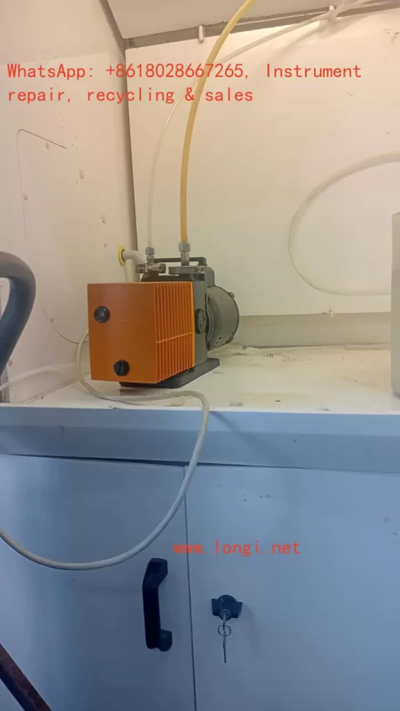
8. The External Vacuum Source Itself May Indeed Have Problems, but It Is Usually Not the First Priority
Of course, the vacuum pump itself or the external vacuum piping is not entirely immune to faults. For example, pump blade wear, pump cavity blockage, filter clogging, air intake leaks, piping aging and cracking, hose kinking and collapse, fitting loosening, and abnormal exhaust can all lead to insufficient vacuum. However, in Laurell WS-650 cases, if the screen clearly displays a CDA prompt, the external pump itself should not be the first suspect.
The scenarios where it is truly necessary to prioritize checking the pump itself are as follows: the CDA is normal, and the screen no longer displays gas source-related prompts; the sample and O-ring are fully matched; the O-ring is clean and intact; the vacuum valve action can be confirmed; but the system still cannot reach the required vacuum value. Only then is it logical to suspect insufficient pump performance. Otherwise, immediately replacing the pump upon seeing a lack of adhesion is often a typical error in maintenance sequence.
From engineering experience, external pump faults usually exhibit more explicit characteristics, such as a long-term inability to reach the required vacuum value, abnormal pump noise, abnormal temperature rise, abnormal exhaust at the pump outlet, and an inability to reach basic negative pressure even when disconnected from the equipment for separate testing. If the customer only says “the pump can be heard making a sound,” it actually only indicates that the pump motor may be running and does not prove that the pump efficiency is normal, let alone that the internal interlock of the equipment has been released.
9. How to Quickly Establish a Correct Fault Judgment Logic Based on On-site Phenomena
For third-party readers, the most valuable aspect is not memorizing the name of a specific part but establishing a replicable judgment path. When facing the problem of “the vacuum pump makes a sound, but the spin coater does not adhere,” the best approach is not to immediately disassemble the machine but to first narrow down the scope in a logical order.
Step 1: Look at the screen prompts. If there are messages like “Need CDA,” prioritize addressing the gas source problem; if there are only vacuum-related prompts, then proceed to check the sample, O-ring, and vacuum path. Step 2: Examine the sample status. Check whether the sample is large enough, whether it fully covers the O-ring, whether the correct adapter is used, and whether the position is centered. Step 3: Inspect the O-ring status. Check for aging, deformation, adhesive contamination, or incorrect installation. Step 4: Check the external connections. Verify whether the vacuum and gas pipes are connected correctly, whether the quick-connect fittings are loose, and whether the hoses are kinked. Step 5: Only then consider vacuum valve contamination or insufficient external pump performance.
The advantage of this troubleshooting path is that it prioritizes the exclusion of the most common, least expensive, and easiest-to-verify problems, minimizing the risk of disassembly. Because many on-site faults ultimately turn out not to be caused by a damaged main board or pump but rather by issues such as an unopened gas source, an incorrectly placed sample, a dirty O-ring, or a loose fitting. True professionalism lies not in immediately replacing parts but in using the fewest actions to eliminate the most uncertainties.
10. A Typical On-site Misconception: Interpreting Program Run Failures as Electronic Control Faults
In the program running logic of the Laurell WS-650, vacuum retention is just one of the startup conditions. If the equipment’s vacuum retention is not satisfied, the program may not enter the normal running state at all or may stop running immediately after starting. Some operators, upon seeing that the program cannot run, immediately suspect problems with the controller, keypad, or program parameters and even believe that there are issues with interface elements such as F1, F2, and Run Mode. In fact, in many cases, the controller itself is completely normal; it is simply faithfully executing the interlock logic.
This is also why third-party maintenance personnel should not focus solely on the表象 (superficial phenomenon) of “the program not running” during troubleshooting. A spin coater is essentially a process equipment, not an ordinary household appliance. Its controller integrates many mechanical and pneumatic conditions for comprehensive judgment. As long as the vacuum retention is insufficient, the cover is not closed, the sealing gas pressure is insufficient, or the exhaust status is incorrect, the controller will prohibit running or interrupt the running process. Therefore, program failures are not necessarily program problems, and interface error codes do not necessarily indicate board card problems; often, they are simply reminding the operator that the peripheral conditions are not met.
11. Why Third-party Maintenance Personnel Must Pay Attention to Customers’ Usage Habits and Cleaning Methods
Industrial equipment faults are never just about “parts being broken”; in many cases, they are the cumulative result of usage methods. This is especially true for spin coaters. Many vacuum problems do not occur suddenly on a particular day but are the result of long-term non-standard usage. For example, regularly placing small samples directly on a large chuck; frequently using O-rings of inappropriate materials; extensively flushing the sealing area during cleaning; allowing sample coating leakage without timely treatment; not cleaning the adapter after use and directly reinstalling it; mixing different chemical systems, causing seal expansion; and failing to restore the standard O-ring configuration in a timely manner after shutdown, etc.
These behaviors may not immediately cause faults in the short term but can gradually damage the vacuum path and valves. By the time the customer realizes that “the vacuum cannot be established no matter what,” it is often no longer a single minor issue but a combination of usage, maintenance, and interlock condition problems. If third-party maintenance personnel ignore this aspect and simply replace parts mechanically, they are likely to only provide a temporary