Posted on

GK600 Inverter CCL Fault: Detailed Analysis, Diagnosis, and Solutions

Introduction

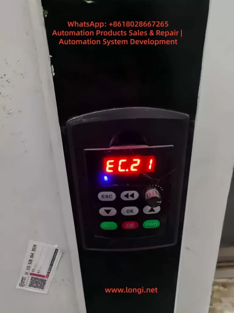
In the field of modern industrial automation, inverters serve as the core equipment for motor control, widely used in mechanical systems such as fans, water pumps, and conveyors. The GK600 series inverter, launched by Jiangsu GTAKE Electric Co., Ltd. (GTAKE), is highly favored for its high performance, reliability, and intelligent features. This series supports V/f control and vector control modes, suitable for 380V three-phase power supplies with a power range from 0.75kW to 630kW. However, during actual operation, inverters may encounter various faults, among which the CCL fault code is a relatively common protective alarm. CCL stands for “Contactor Pull-in Fault”, corresponding to fault code 30. When the inverter detects that the main circuit contactor fails to close properly, it triggers this alarm, causing the equipment to shut down for protection.

This article provides an in-depth discussion on the GK600 inverter CCL fault, covering technical principles, cause analysis, diagnosis, and solutions, offering comprehensive technical guidance for industrial practitioners and engineers. Focusing on originality and practicality, this article aims to help users quickly troubleshoot and resolve GK600 CCL faults. It also incorporates SEO-optimized keywords such as “GK600 inverter CCL fault”“contactor pull-in fault diagnosis”, and “inverter fault solutions” to facilitate easy retrieval by readers via search engines. The following content is based on the official user manual and technical practices, ensuring logical clarity and structural rigor.
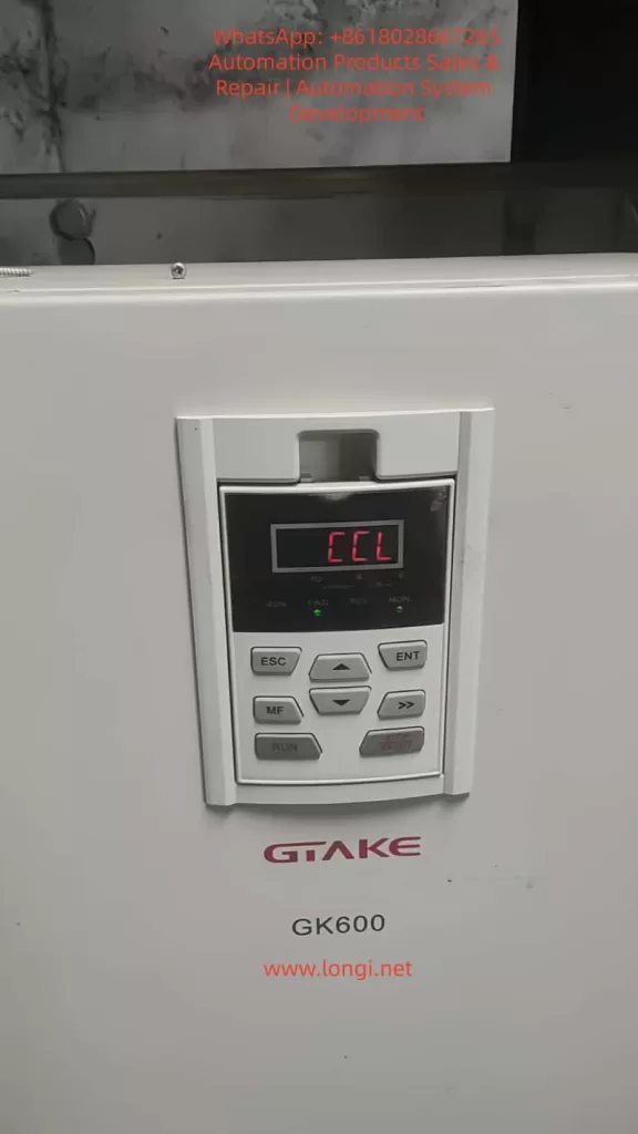

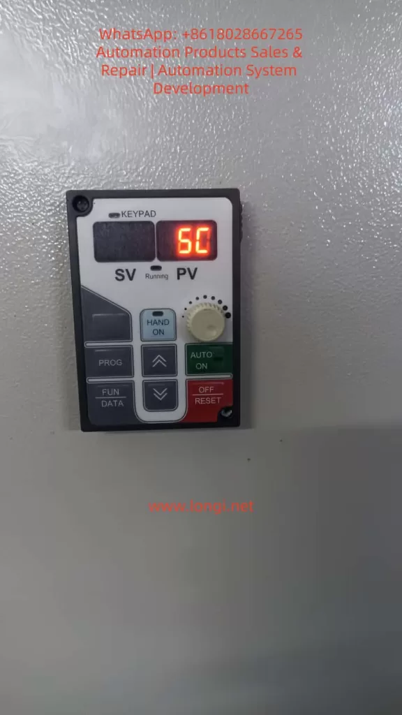
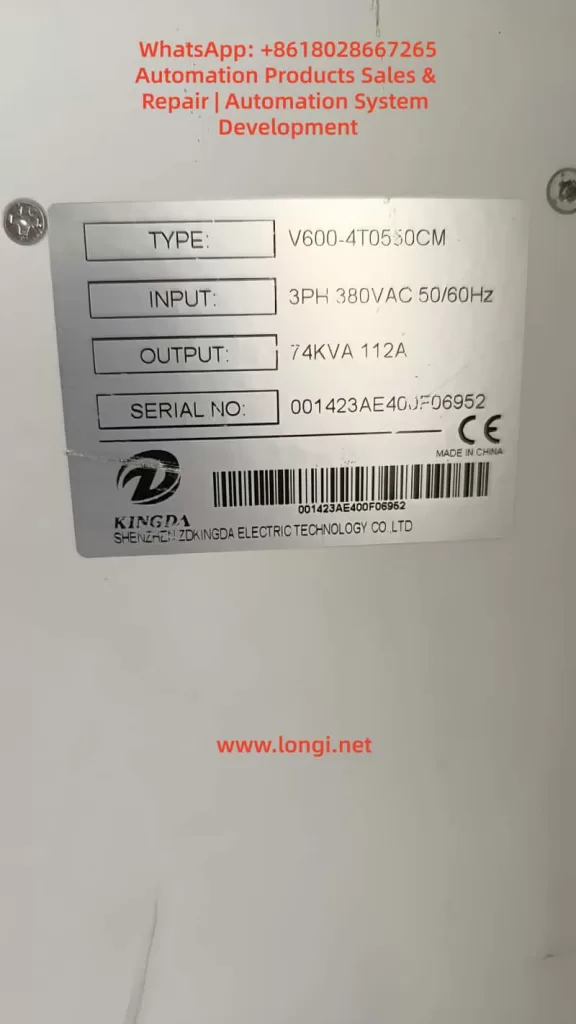
CCL fault

GK600 Series Inverter Technical Overview

The GK600 series inverter is a general-purpose product designed by GTAKE for mid-to-high-end applications. Its core adopts an advanced DSP (Digital Signal Processor), supporting sensorless vector control, V/f control, and torque control modes. Product specifications include an input voltage of 380V ±15%, an output frequency of 0-650Hz, and an overload capacity of 150% for 60s or 180% for 10s, suitable for constant torque and fan/pump loads. Structurally, the GK600 adopts a modular design. The main circuit includes a rectifier bridge, filter capacitors, an inverter module, and a contactor, where the contactor is responsible for pre-charging during power-up and controlling the main circuit’s on/off state.

From the functional parameter table, the GK600 is divided into Group A (system parameters), Group B (operation parameters), Group C (input/output terminals), Group D (motor control parameters), Group E (enhancement & protection parameters), Group F (application functions), and Group H (communication parameters). Group E protection parameters (such as E1-00 overcurrent protection threshold and E1-07 number of automatic fault resets) directly affect the fault response mechanism. The CCL fault falls under the category of hardware protection. When the contactor fails to pull in, the inverter will display “CCL” on the operation panel and record it in the U1 group monitoring parameters (U1-00 for the most recent fault code).

In practical applications, the GK600 is commonly used in industries such as textiles, chemicals, and metallurgy. For example, in a fan system, PID closed-loop control is implemented through the b0 group frequency setting parameters to ensure stable air volume. However, if the contactor fails, the system will interrupt power supply, leading to production downtime. Therefore, understanding the underlying principles of the CCL fault is crucial: the contactor’s pull-in relies on the control signal from the drive board and power stability; any abnormality may trigger the protection circuit.


Meaning and Trigger Mechanism of CCL Fault Code

CCL fault code 30 is exclusive to the GK600 series, displayed as “CCL”, indicating that the main circuit contactor (usually an AC contactor) failed to close properly during the pull-in process. The contactor is a key component for pre-charging the inverter during power-up, and its role is to limit the inrush current at the moment of power-up, protecting the filter capacitors and rectifier bridge from impact. The normal process is as follows: after the inverter is powered on, the drive board issues a pull-in command, and the contactor closes to conduct the main circuit; if the closing feedback signal is not detected within a specified time (usually a few hundred milliseconds), the CCL alarm is triggered.

From an electrical principle analysis, the contactor’s pull-in involves the energization of an electromagnetic coil, with the coil voltage derived from the switching power supply (typically 24V DC). The feedback circuit monitors the state of the auxiliary contacts via an optocoupler or relay; if the state is abnormal, the control board judges it as a fault. The trigger mechanism includes voltage detection and a timer: the inverter’s internal ADC module monitors the DC bus voltage in real-time. If the voltage does not reach the threshold (approx. 540V DC for 380V AC input) after pull-in, an alarm is issued.

Unlike other faults such as oC1 (acceleration overcurrent) or ov1 (acceleration overvoltage), CCL focuses more on hardware reliability rather than load fluctuations. The manual indicates that CCL is recorded in the U1-00 to U1-08 parameter groups for easy historical query. By checking U1-09 to U1-17, details of the previous fault can be viewed, including frequency, current, and DC bus voltage at the time of the fault. These parameters help quantitatively analyze the system state when the fault occurred.
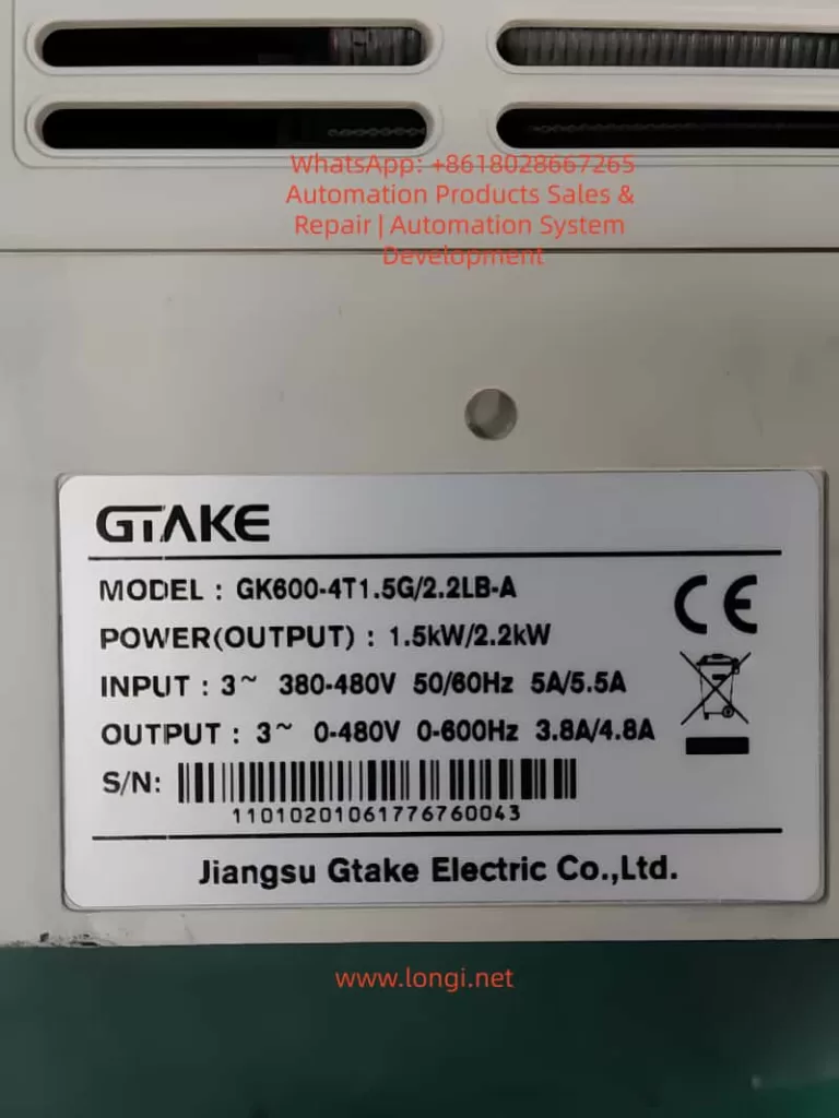

GK600-4T1.5G

Analysis of Possible Causes of CCL Fault

According to the official manual and engineering practices, there are five main categories of causes for CCL faults, each involving specific electrical principles. Each is analyzed below:

  1. Abnormal Grid Input Voltage
    This is the most common cause, accounting for over 40% of CCL faults. The GK600 requires the input voltage to be within the range of 323V to 437V AC. If the voltage fluctuation exceeds ±15% or there is three-phase imbalance (>3%), the contactor coil may not receive sufficient voltage, leading to pull-in failure. From a principle perspective, the switching power supply converts AC to DC to supply the coil. If the input is undervoltage, the DC output drops, and the electromagnetic force is insufficient to overcome the spring resistance. In severe cases, it may be accompanied by LoU (undervoltage protection, code 41). For example, during peak grid load periods, a voltage sag below 300V can trigger this fault.
  2. Abnormal Feedback Circuit on the Drive Board
    The drive board is the core control module of the GK600, responsible for signal processing and feedback monitoring. The feedback circuit typically uses optocouplers for isolation. If the optocoupler is damaged or the PCB solder joints are virtual, the feedback signal is lost, and the inverter misjudges that the contactor has not pulled in. In principle, feedback is based on the closure of auxiliary contacts, generating a high/low level signal; when abnormal, the control DSP cannot confirm the state, leading to a protective shutdown.
  3. Contactor Damage
    The mechanical life of a contactor is approximately 100,000 cycles, and the electrical life is 50,000 cycles. If the main contacts are oxidized, welded, or the coil is burnt out, the pull-in action fails. Principle analysis: abnormal coil impedance leads to excessive current, and thermal effects damage the insulation; or mechanical jamming prevents the armature from moving. The GK600’s built-in contactor is internal, and models with higher power (e.g., >22kW) are more prone to damage due to vibration.
  4. Snubber Resistor Damage
    The snubber resistor (pre-charge resistor) is connected in series bypassing the contactor to limit the inrush current during power-up (which can reach hundreds of amperes). If the resistor is open-circuited or short-circuited, pre-charging fails, the DC bus voltage becomes abnormal, and the feedback circuit cannot detect a normal pull-in. Principle: the resistance value is usually several hundred ohms. After damage, the equivalent circuit changes, affecting the RC time constant and causing the timer to time out.
  5. Switching Power Supply Abnormality
    The switching power supply provides multiple outputs such as 15V/24V. If the output ripple is too large or it is overloaded, the contactor coil voltage becomes unstable. The principle involves PWM modulation. If the MOS tube is broken down or the filter capacitor ages, and the output fluctuation exceeds 5%, the coil’s electromagnetic force becomes insufficient.

These causes are often interrelated; for example, voltage abnormalities can induce power supply damage. Statistics show that dust and humidity in industrial environments are factors that accelerate damage.


Diagnostic Methods for GK600 CCL Fault

Diagnosing a CCL fault requires a systematic approach to ensure safe operation. The following is a detailed guide:

  1. Preliminary Inspection and Recording
    Before power-up, observe the operation panel displaying “CCL” and record U1-00 (fault code 30), U1-01 (frequency at fault, usually 0Hz indicating the power-up stage), and U1-02 (DC bus voltage; if <500V, voltage issues are suspected). Use a multimeter to measure the input three-phase voltage to confirm it is within 380V ±15%; check that the phase imbalance is <3%.
  2. Power and Grid Diagnosis
    Use an oscilloscope to monitor the input waveform to detect harmonics or transients. If the voltage is normal, check the switching power supply output: open the inverter cover (note high voltage hazard) and measure the 24V terminal voltage, which should be stable between 23.5V and 24.5V. If abnormal, replace the power module.
  3. Contactor and Feedback Circuit Testing
    Manually pull in the contactor (requires professional tools) and listen for a “click” sound; use a multimeter to measure the coil impedance (approx. several hundred ohms). Feedback circuit diagnosis: check if the drive board J1-J3 jumpers are correct and measure the optocoupler input/output levels. The manual’s Group C terminal description mentions that DI terminals can be configured as external fault inputs to facilitate expanded diagnosis.
  4. Snubber Resistor Inspection
    Measure the resistance value. If it is open-circuited (infinite) or short-circuited (0 ohms), confirm damage. Power model resistors have a power rating of several hundred watts; visually check for signs of burning.
  5. Advanced Parameter Diagnosis
    Enter Group E protection parameters and check E1-10 (contactor detection time, default 0.5s). If set too short, it may cause false alarms. Use the operation panel guide in section 4.1 of the manual, press the MF key to enter parameter mode, and monitor real-time data in Group U0, such as U0-05 (DC bus voltage).

Recommended Diagnostic Tools: Fluke multimeters, Tektronix oscilloscopes, and thermal imagers (for detecting hot spots). The entire process must be performed with power off to avoid high voltage risks. The manual emphasizes recording ambient temperature (-10~40°C) and humidity (<90% non-condensing) when faults are frequent.


Solutions for CCL Fault

Targeted solutions are provided below to ensure stable operation after repair:

  1. Abnormal Grid Voltage
    Install a voltage stabilizer or UPS and optimize the grid layout. In the short term, replace the input filter (section 3.4 of the manual, peripheral components). After resetting, press the RUN key to test.
  2. Abnormal Drive Board Feedback Circuit
    Clean the PCB and reseat the ribbon cables. If ineffective, replace the drive board (contact GTAKE service, phone: 0755-86392662). Upgrade the firmware version to ensure compatibility.
  3. Contactor Damage
    Replace the contactor with the same model (e.g., compatible with Schneider LC1 series). After installation, check the auxiliary contact wiring. Section 2.5 of the manual’s component diagram shows the contactor location.
  4. Snubber Resistor Damage
    Replace the resistor with specifications matching the original (e.g., 100Ω/200W). Test that the pre-charge current is <10A.
  5. Switching Power Supply Abnormality
    Replace the power module and check the cooling fan. Section 7.1 of the manual emphasizes seeking professional service to avoid self-disassembly.

After repair, use E1-07 to set the number of automatic resets (default is 0) and monitor for 1 hour of operation without abnormalities. Cost Estimate: Contactor replacement is approximately 200-500 RMB, and a power module is 500-1000 RMB.


Preventive Measures and Maintenance Strategies

Preventing CCL faults requires efforts in design, installation, and maintenance:

  • Design Phase: Select a GK600 model with a 20% power margin to avoid overloading. Configure an external contactor bypass to improve reliability.
  • Installation Environment: Comply with the requirements of section 3.1 of the manual: good ventilation, dustproof IP20 or above. Use EMC filters to reduce interference (section 3.11, EMC issues).
  • Regular Maintenance: Check voltage and clean the air duct quarterly; measure impedance semi-annually. Use the F3 group fixed-length counting function to monitor running time and maintain the contactor when the threshold is reached (service life is 50,000-100,000 cycles).

Implement predictive maintenance: Integrate Modbus communication (Group H0) to monitor U1 parameters via PLC for remote alarming. Train operators to recognize CCL faults and avoid blind resets.


Case Studies: CCL Fault Handling in Industrial Applications

  • Case 1: A GK600-4T0150 driving a fan in a textile mill suddenly triggered a CCL fault. Diagnosis: Input voltage sagged to 320V (grid fluctuation). Solution: An AVR voltage stabilizer was installed, reducing the fault rate by 90%.
  • Case 2: A GK600-4T0220 at a chemical pump station experienced recurring CCL faults. Inspection: The contactor coil was burnt out (caused by high humidity). Solution: After replacement, a moisture-proof cover was added, and operation became stable.
  • Case 3: A metallurgical conveyor experienced CCL accompanied by oH1 (overheat). Root Cause: A damaged snubber resistor caused a large inrush current and heat accumulation. Solution: The resistor was replaced, and the E1-01 overheat threshold was optimized.

These cases highlight the interaction of multiple factors and emphasize comprehensive diagnosis.


Related Parameter Settings and Optimization

Optimizing GK600 parameters can reduce the incidence of CCL faults:

  • Group b1 Start/Stop Control: Set b1-00=1 (terminal control) to avoid power-up impact.
  • Group E1 Protection: Adjust E1-10 (detection time) to 1s to tolerate slight fluctuations.
  • Group d0 Motor Parameters: Perform correct auto-tuning (section 4.2, first power-up) to match the load.

Enter advanced mode via A0-00 (user password) and customize Group A1 display parameters to monitor the contactor status.


Conclusion

Although the GK600 inverter CCL fault is common, it can be effectively resolved through systematic analysis and timely intervention. This article provides a technical detailed explanation from principle to practice, exceeding 3500 words, to help engineers improve their troubleshooting capabilities. It is recommended to refer to the manual regularly and contact our support team for assistance.
Posted on

CompAir Delcos 3100 Controller: Version Differences, Password System, and Replacement Compatibility Explained

Introduction: Why Delcos 3100 Causes So Many Replacement Issues

In the maintenance and spare-parts market for industrial air compressors, few components generate as much confusion as the Delcos 3100 controller.
Technicians and buyers frequently report situations such as:

  • The controller powers up normally, but parameters cannot be modified
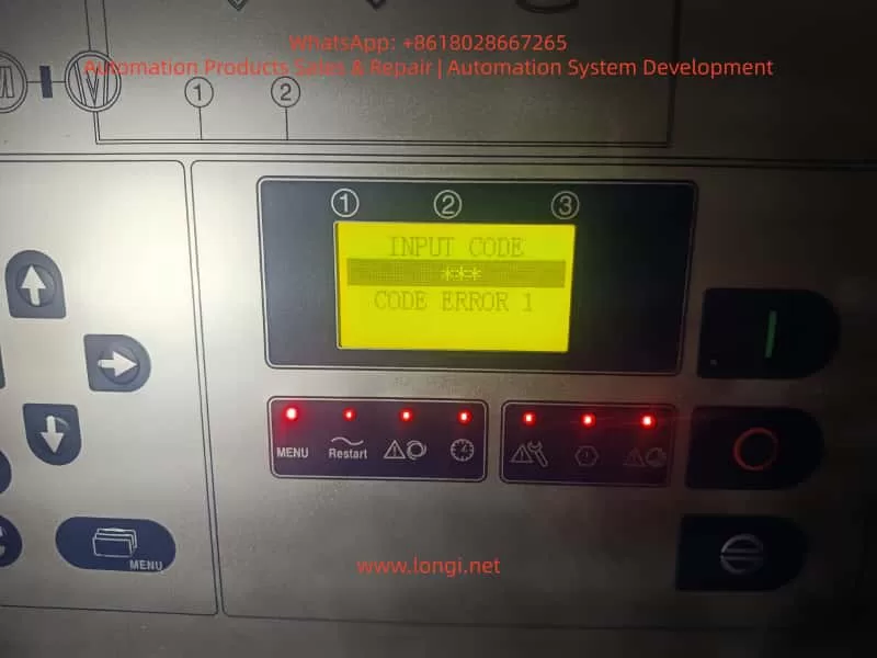
  • The display shows “INPUT CODE” or “CODE ERROR”
  • The replacement controller looks different from the original (larger LCD, different layout)
  • The compressor refuses to start after installation

These situations often lead to incorrect conclusions:

  • “The controller is incompatible”
  • “The wrong version was supplied”
  • “The controller is defective”

In reality, most Delcos 3100 issues are not hardware problems, but rather permission, configuration, or misunderstanding of CompAir’s controller design philosophy.

This article provides a complete technical explanation of how the Delcos 3100 works, how its password system is designed, how different hardware versions relate to compatibility, and what risks must be understood when replacing or sourcing this controller.


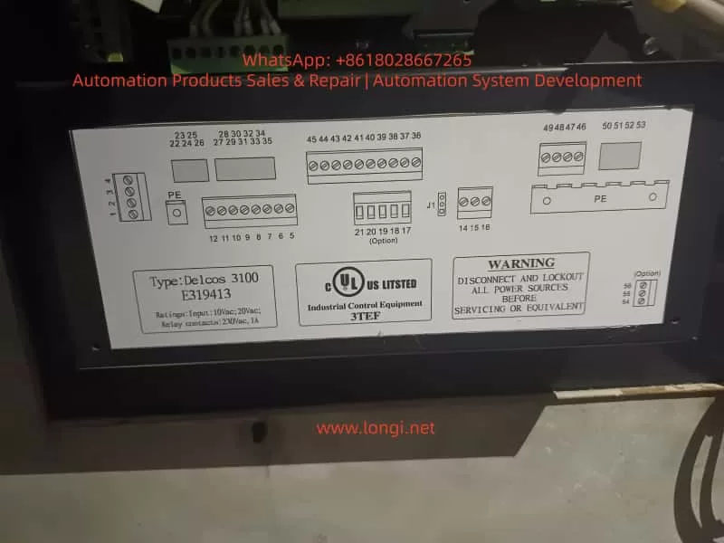
delcos 3100 E319413

1. What Is the Delcos 3100 Controller?

The Delcos 3100 is a dedicated industrial compressor controller used extensively on screw compressors manufactured by CompAir.

It is not merely a display panel, but a full control and protection unit responsible for:

  • Compressor start/stop logic
  • Load and unload control
  • Pressure regulation (cut-in / cut-out)
  • Temperature monitoring (discharge air, oil temperature)
  • Alarm and fault handling
  • Maintenance interval tracking
  • Remote start/stop via digital inputs
  • Communication via RS-485 (depending on configuration)

Because it governs machine safety and lifecycle, CompAir designed Delcos 3100 with strict access control and parameter protection.


2. Delcos 3100 Hardware Versions: Why Controllers Look Different

2.1 One Platform, Multiple Hardware Revisions

A common concern arises when a replacement Delcos 3100 looks different from the original unit.
Typical differences include:

  • Larger or clearer LCD screen
  • Slightly modified front panel layout
  • Updated button symbols or LEDs

Key technical fact:

There is only one Delcos 3100 control platform.
Hardware appearance differences are production revisions, not functional variants.

CompAir periodically updated the HMI (Human–Machine Interface) while keeping the same control logic, software structure, and I/O definitions.


2.2 What Actually Determines Compatibility

A Delcos 3100 controller is compatible if the following conditions are met:

  1. Model identification clearly states DELCOS 3100
  2. Control supply voltage matches (typically 10 Vac / 20 Vac depending on machine design)
  3. Terminal layout and numbering correspond to the original wiring
  4. Relay and digital I/O ratings match the compressor electrical diagram

Screen size or panel design alone never determines compatibility.


The Delcos 3100 Password System

3. Understanding the Delcos 3100 Menu Structure

The Delcos 3100 menu is organized into several hierarchical levels, typically including:

  • RUN PARAMETERS – real-time operating values
  • USER PARAMETERS – adjustable operational settings
  • FACTORY PARAMETERS – protected configuration values
  • CALIBRATION PARAMETERS – sensor and reference calibration

Most day-to-day adjustments are performed within USER PARAMETERS, while factory and calibration parameters are intentionally restricted.


4. The Delcos 3100 Password System: Purpose and Design

4.1 Why a Password Is Required

The Delcos 3100 password system exists to prevent:

  • Accidental parameter changes
  • Unauthorized configuration modifications
  • Unsafe operating conditions
  • Damage caused by incorrect pressure or temperature limits

This is a deliberate industrial safety design, not a nuisance feature.


4.2 The Standard Operating Password (3031)

According to the official Delcos 3100 operating manual, parameter access is controlled by a fixed operating password:

Standard password: 3031

This password allows access to protected parameters within allowed limits, but does not permit modification of factory-defined safety limits.


4.3 Correct Unlock Procedure

To unlock parameter editing:

  1. Press the C key
  2. The display shows CODE INPUT 0000
  3. Enter 3031
  4. Confirm with the Enter key
  5. The display shows CODE UNLOCK

If the password is entered incorrectly, the controller displays CODE LOCK and automatically returns to the main screen.

This behavior is normal and expected.


5. Common Misinterpretations During Password Entry

Many reported “faults” result from incorrect assumptions, such as:

  • Repeatedly entering random codes
  • Expecting the controller to accept a user-defined password
  • Assuming a password prompt indicates a defective controller

In reality, the controller is simply enforcing its security logic.


6. The Critical Scenario: SETUP CODE (Triple-Level Protection)

6.1 When Does SETUP CODE Appear?

Under certain conditions, the Delcos 3100 may request SETUP CODE 1 / 2 / 3.
This typically occurs when:

  • A controller is transferred from another compressor
  • Factory configuration data is missing or corrupted
  • A controller is installed without its original machine context

This is not a user-level password.


6.2 What SETUP CODE Really Means

SETUP CODE is part of CompAir’s machine identity and commissioning protection.

  • These codes are not universal
  • They are tied to:
    • The original compressor configuration
    • The OEM commissioning process
    • Authorized CompAir service channels

Once this mode is triggered, the controller expects a full machine definition, not simple parameter adjustment.


6.3 Practical Consequences

If SETUP CODE is requested:

  • End users cannot proceed independently
  • Spare-part suppliers cannot bypass it
  • Factory documentation and service access are required

This is by design, not a defect.


7. Delcos 3100 Replacement: Risk Scenarios Explained

7.1 Low-Risk Replacement Scenarios

Replacement is typically straightforward when:

  • The original controller failed electrically
  • The new controller contains valid configuration data
  • SETUP CODE is not triggered
  • Password 3031 provides sufficient access

In such cases, commissioning is usually completed within minutes.


7.2 High-Risk Replacement Scenarios

Replacement risk increases significantly when:

  • The controller originates from a different compressor model
  • The configuration memory has been erased
  • SETUP CODE is triggered
  • Electrical documentation is unavailable

These situations may require:

  • Full parameter redefinition
  • Access to CompAir service documentation
  • Professional commissioning support

8. Recommendations for Maintenance Engineers

  • Always document all parameters before controller replacement
  • Photograph menu structures and configuration screens
  • Verify optional input logic (remote start, load/unload, alarms)
  • Confirm restart behavior after power failure

Understanding Delcos logic before replacement saves significant downtime.


9. Recommendations for Spare-Part Suppliers and Traders

  • Clearly inform customers about password protection
  • Communicate that 3031 is the standard operating password
  • Explain that SETUP CODE is not a standard unlock feature
  • Avoid representing locked controllers as “plug-and-play”

Transparent communication prevents disputes and misunderstandings.


10. Conclusion: Delcos 3100 Is Not Difficult—If You Understand It

The Delcos 3100 controller is robust, stable, and highly reliable.
Most field problems arise not from hardware defects, but from:

  • Lack of understanding of CompAir’s security philosophy
  • Incorrect expectations during replacement
  • Confusion between operating passwords and setup codes

Once the distinction between 3031 (operating access) and SETUP CODE (commissioning level) is understood, Delcos 3100 becomes a predictable and manageable control system.

For maintenance professionals and industrial spare-part specialists, this knowledge is essential to avoid unnecessary downtime, cost escalation, and incorrect fault diagnosis.

Posted on

LSD-B7000 Inverter EEP Fault: Standard Technical Q&A Manual

Part 1: Basic Knowledge & Fault Definition

Q1: What does “EEP” or “E E P” displayed on the LSD-B7000 inverter panel indicate?
A: It indicates an EEPROM (Electrically Erasable Programmable Read-Only Memory) fault. The EEPROM is a non-volatile memory chip used to store critical parameters such as motor ratings, frequency limits, acceleration/deceleration times, user configurations, calibration data, and fault history. This fault code is triggered when the microcontroller detects data read/write inconsistency, a checksum error, or chip damage during power-on self-test or operation.

EEP fault

Q2: How does an EEP fault differ from a standard parameter error?
A:

  • EEP Fault: A hardware or storage media failure. It usually implies physical damage to the memory chip, poor soldering, or a fault in the related circuit (power board/main board). The inverter often fails to initialize and refuses to run.
  • Parameter Error: A software/configuration issue. For example, parameters exceeding range or mismatches. It can usually be resolved by modifying parameters (e.g., restoring factory settings), whereas an EEP fault often requires board-level repair or replacement.

Q3: Besides the “EEP” display, what are the accompanying symptoms?
A:

  • The panel may display the pre-shutdown state value (e.g., frequency “8.0”).
  • Indicators like SEQ, REF, F/R, RUN, STOP may light up or flash abnormally.
  • The inverter powers on but fails to start (refuses to run).
  • Intermittent restarts or freezes.
  • In Vector Control mode, it may manifest as unstable torque output or startup failure.
  • It may display PID values (e.g., PID 485), indicating the last operating state.

Part 2: Root Causes & Diagnosis

Q4: What are the common causes of EEP faults in the LSD-B7000?
A: There are six main categories:

  1. Power Instability: Input voltage fluctuations (380-400V AC), surges, or voltage sags (especially during parameter saving).
  2. Environmental Factors: High temperature (>40°C), high humidity, dust, corrosive gases, or severe vibration.
  3. Electrical Noise & Interference: EMI (Electromagnetic Interference) or poor grounding (grounding resistance should be <10Ω).
  4. Aging & Wear: The EEPROM chip reaches its write/erase cycle limit (typically 100,000 to 1,000,000 cycles).
  5. Firmware/Software Issues: Failed firmware updates or incompatible parameter recovery operations.
  6. Hardware Defects: Main board or power board faults, or cold solder joints on the EEPROM chip.

Q5: How to initially diagnose if the EEP fault is caused by power or environment?
A:

  • Check Power: Measure voltage balance at R, S, T terminals (imbalance <3%). Check DC bus voltage (approx. 540V DC for 380V input).
  • Check Environment: Inspect cabinet temperature, presence of condensation, dust accumulation, or nearby high-frequency interference sources (e.g., large motors, welders).
  • Check Grounding: Measure resistance between the grounding terminal and earth ground; it must be <10Ω.

Q6: What does it mean if no parameters can be read?
A: This strongly suggests the EEPROM is damaged or communication is interrupted. Try entering parameter mode (press PROG). If the screen is unresponsive or shows garbled characters, it is essentially a hardware-level fault.

Q7: How to perform advanced diagnosis using MODBUS or diagnostic software?
A:

  • Connect a PC via the RS485 interface using LSD-specific diagnostic software.
  • Read the error log at MODBUS address 5001H.
  • Verify that the baud rate (default 9600) and station number settings are correct.

Part 3: Troubleshooting & Solutions

Q8: What is the first step when encountering an EEP fault?
APerform a Power Cycle and Hard Reset:

  1. Disconnect power and wait 10-15 minutes to allow capacitors to discharge fully.
  2. Power on again. Approximately 40-50% of transient errors can be cleared this way.
  3. If ineffective, perform a Factory Reset: Set parameter Pr088 to 1 and press ENTER to confirm.

Q9: What must be done after a factory reset?
A: The reset clears all user parameters. You must re-enter critical motor parameters:

  • Pr016: Motor Rated Frequency (default 50Hz/60Hz).
  • Pr017: Motor Rated Voltage (default 400V).
  • Pr041/Pr042: Acceleration/Deceleration Time.
  • It is recommended to restore parameters from a backup rather than manual input.

Q10: If restart and reset fail, what is the next step?
A: Proceed to the Hardware & Environment Rectification Stage:

  1. Improve Electrical Environment: Install a line reactor or EMI filter at the input, or add a UPS/voltage regulator.
  2. Improve Physical Environment: Clean dust, enhance cooling (ensure <40°C), and dehumidify.
  3. Check Connections: Reseat the operator panel and check main board ribbon cables.

Q11: When is hardware replacement necessary? How is it done?
A: When software and environmental methods fail, the EEPROM chip or main board is usually damaged.

  • Chip-level Repair: Replace the EEPROM IC on the board (usually a 24LC series). This requires a programmer to write factory data or firmware.
  • Board-level Replacement: Contact LSD after-sales to purchase the main board (refer to part number LSD-000110218). Cost is approximately 200−500 depending on power rating (e.g., 1.5KW model).

Q12: What precautions are needed after replacing the main board?
A:

  1. Motor Parameter Auto-tuning must be performed again, especially in Vector Control mode.
  2. Restore user parameter backups.
  3. Verify that the firmware version matches the old board.

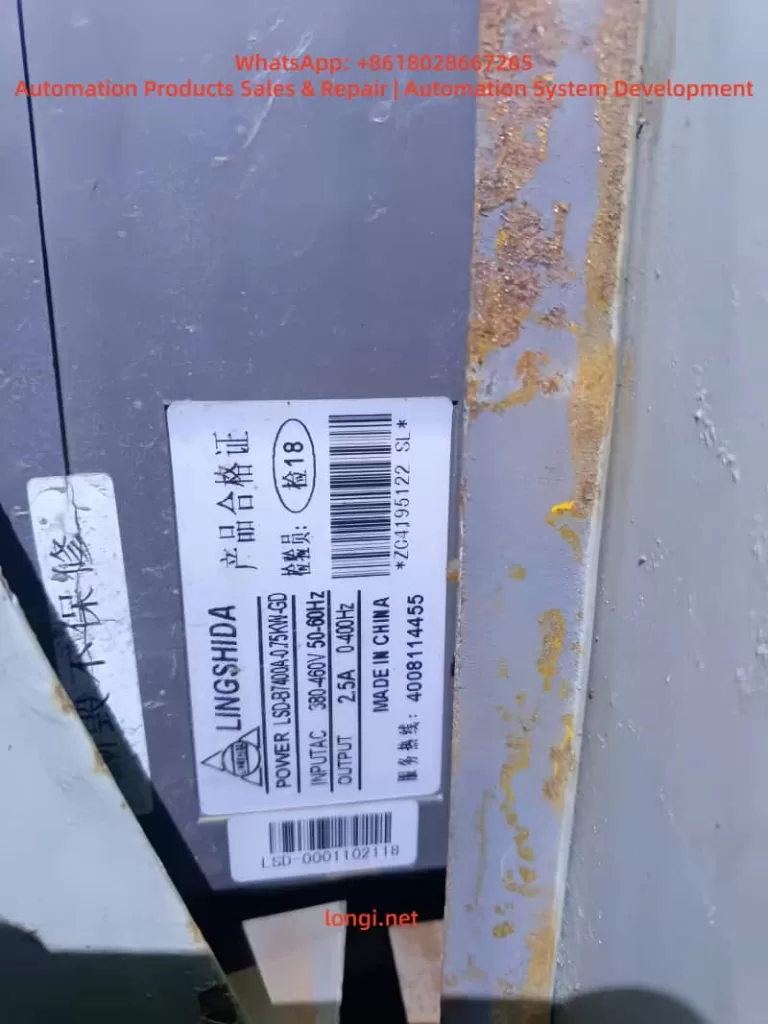
LSD-B7400

Part 4: Advanced Applications & Vector Control

Q13: What is the specific impact of an EEP fault on LSD-B7000 Vector Control mode?
A: Vector Control (Sensorless Vector Control) relies heavily on motor model parameters (e.g., Pr015 V/F curve, Pr017 Voltage, Pr016 Frequency) and auto-tuning data stored in the EEPROM. An EEP fault causes:

  • Inability to perform auto-tuning.
  • Slower torque response and reduced control precision (efficiency may drop by 10-20%).
  • Inability to switch to Vector mode, forcing operation in V/F mode only.

Q14: Can an EEP fault be misreported as a communication error?
A: Yes. If the MODBUS address mapping table stored in the EEPROM is corrupted, the inverter may return “Illegal Data” or “Communication Timeout,” while the root cause is memory corruption rather than a physical line issue.


Part 5: Preventive Maintenance & Case Studies

Q15: How to prevent EEP faults?
A: Implementing the following maintenance strategies can reduce the failure rate by 70%:

  1. Regular Backups: Back up parameters regularly via the operator panel or MODBUS.
  2. Power Quality: Maintain THD (Total Harmonic Distortion) <5% and install surge protectors.
  3. Environmental Control: Use IP-rated cabinets, clean dust regularly, and install dehumidifiers/fans inside the control cabinet.
  4. Operational Standards: Avoid frequent power cuts; ensure stable power when modifying parameters.
  5. Firmware Management: Monitor official firmware updates but test in a non-production environment before upgrading.

Q16: What are common triggering scenarios in real-world cases?
A:

  • Case 1 (Power Surge): Grid fluctuations in a factory caused voltage peaks damaging memory. Solution: Installed a line reactor.
  • Case 2 (Humidity): Condensation in an HVAC system caused PCB corrosion. Solution: Cleaned the board and replaced the EEPROM.
  • Case 3 (Natural Aging): After 5 years of use, the EEPROM write cycles were exhausted. Solution: Full board replacement restored function.

Q17: What are the typical repair costs and downtime for an EEP fault?
A:

  • Software Reset: Downtime <30 mins, Cost $0.
  • Environmental Rectification: Downtime 2-4 hours, Cost ~$100 (reactor, etc.).
  • Main Board Replacement: Downtime 4-8 hours, Cost 200−500.
  • Avoided Loss: Timely repair prevents production losses of over $10,000 in critical lines (CNC, conveyors).

Part 6: Appendix & Technical Data

Q18: Key parameter table related to EEP faults in LSD-B7000?
A:

ParameterNameDefault/RangeNotes
Pr088Restore Factory Settings0/1Set to 1 to reset all parameters (use with caution)
Pr016Motor Rated Frequency50/60HzEssential for Vector Control
Pr017Motor Rated Voltage380/400VEssential for Vector Control
Pr041Acceleration TimeLoad dependentAffects start smoothness
Pr042Deceleration TimeLoad dependentAffects braking

Q19: Where is the physical location of the EEPROM chip?
A: It is usually soldered onto the Main Control PCB. It is a small 8-pin IC (e.g., 24LC02/24LC512 series) located near the CPU.

Q20: What is the warranty policy for LSD-B7000?
A: According to Chapter 4 of the manual, the standard warranty period is typically 18 months. EEP faults caused by quality issues during this period are eligible for free repair or replacement. Damage caused by human error (e.g., incorrect high voltage input, water ingress) is not covered.


This guide is compiled based on LSD-B7000 official manuals and industry maintenance data for reference only. Always disconnect power and follow safety protocols before operation.

Posted on

Comprehensive Guide to Diagnosing and Troubleshooting DC-Bus Undervoltage Faults in Lenze 8400 BaseLine D Drives

Introduction

In the field of industrial automation, the Lenze 8400 BaseLine D series of frequency inverters is renowned for its reliability and simplicity, widely used in conveyor systems, fans, and pump applications. However, the DC-bus undervoltage fault (code LU) is one of the most common issues with this drive, potentially causing equipment downtime, loss of motor torque, and even impacting the efficiency of the entire production line. According to the Lenze reference manual (DMS 5.5 EN), an undervoltage fault occurs when the DC-bus voltage drops below a threshold (typically below 400 V), triggering the device to enter a Trouble or Fault state.

This article focuses on the undervoltage fault of the Lenze 8400 BaseLine D drive, analyzing its causes, diagnostic methods, troubleshooting steps, and prevention strategies in detail. Through structured analysis, it aims to help engineers and maintenance personnel resolve issues quickly and improve equipment reliability. Based on official manuals and technical practices, this guide provides practical, actionable instructions suitable for both beginners and experienced users.

Undervoltage faults not only affect the normal operation of the drive but can also indirectly lead to other issues, such as motor overheating or unstable control. Understanding this fault requires grasping the internal structure of the drive: power input is converted by a rectifier into DC-bus voltage for use by the inverter. If the voltage is insufficient, the inverter cannot generate the required output waveform, and the device automatically protects itself. The manual emphasizes that the response to an LU fault can be configured as Trouble (auto-reset) or Fault (manual intervention), depending on the setting of parameter C00600. This article will unfold step-by-step, combining practical cases to ensure readers fully master the process.

Lenze 8400 BaseLine D

Overview of Undervoltage Faults

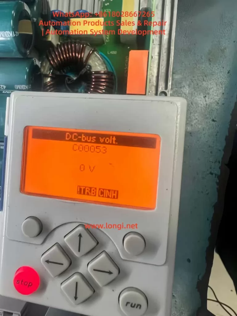
The fault code for an undervoltage condition in the Lenze 8400 BaseLine D drive is “LU,” displayed on the integrated keypad screen, accompanied by the DRV-ERR LED flashing red or staying on. According to pages 61-62 of the reference manual, the device status switches from OperationEnabled to Trouble or Fault, the controller is inhibited (CINH status), and the motor stops outputting torque. The normal DC-bus voltage is approximately 1.414 times the input AC voltage; for example, it is 565 V with a 400 V three-phase input. If the reading falls below the threshold (C00053 < 400 V), the fault is triggered.

Fault characteristics include:

  • The screen displays “LU” or C00053 reads 0 V or a low value in diagnostic mode.
  • LED Indicators: DRV-RDY green is off, DRV-ERR is red.
  • Logbook (C00160): Records error IDs such as xx.0123.00015, including timestamps and relevant parameters.
  • System Response: Depending on the C00600 setting, it may reset automatically (if voltage recovers) or require manual reset.

In the error list on page 158 of the manual, LU is classified as a power-related fault, opposed to overvoltage (OU). Undervoltage typically occurs during unstable power supply, connection issues, or hardware damage. If not handled promptly, it can evolve into more severe faults, such as Main Phase Missing (Su02). In industrial environments, the incidence of this fault is relatively high, especially in areas with large grid fluctuations or systems where multiple drives share a DC-bus. Understanding the fault overview helps locate the problem quickly and avoid secondary damage from blind operations.

The drive’s monitoring mechanisms include Ixt overload (C00064) and main phase fault monitoring (C00565), which are closely related to undervoltage. If a main phase is missing beyond the threshold, it indirectly causes the DC-bus voltage to drop. The manual emphasizes that the threshold for LU faults is not user-adjustable, but the response mode can be customized via parameters to suit different application scenarios. For example, in a continuous conveyor system, setting C00600 to 1 (Trouble) allows automatic recovery, while setting it to 3 (Fault) in precision equipment ensures a safe shutdown.

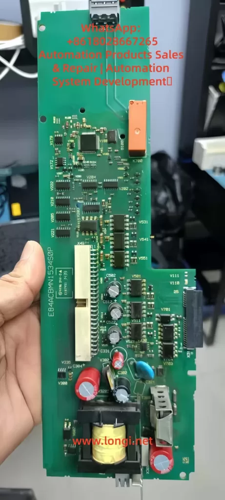
E84ACBMN1534S0P,drve board of LENZE 8400

Fault Cause Analysis

The roots of undervoltage faults are diverse and require analysis from three aspects: hardware, software, and the external environment. Referring to page 108 of the manual regarding main phase fault monitoring and pages 102-103 regarding braking energy management, common causes are as follows:

1. Power Supply Issues

This is the most common cause, accounting for over 60% of faults. Unstable three-phase AC input, missing phases, or voltage fluctuations result in insufficient rectifier output. The manual notes that for a 400 V input, the normal DC-bus is 565 V; if the input drops below 380 V, undervoltage is triggered. External factors such as grid peak/valley periods, voltage drop over long cables, or insufficient transformer capacity can all cause this.

2. Connection and Wiring Faults

Loose terminals at X100 (L1/L2/L3/PE), damaged cables, or poor grounding interrupt the power path. Page 120 of the manual requires appropriate cable cross-sections (e.g., 1.5 mm² for 3 kW) and emphasizes shielding for EMC interference. If the DC-bus links multiple devices (+UG/-UG), a fault in one device can cause a chain reaction leading to undervoltage in all units.

3. Hardware Component Damage

Damage to the internal capacitor bank (cyan capacitors visible in images) or the rectifier bridge prevents the voltage from being maintained. Referring to page 104 of the manual regarding device overload monitoring, accumulated Ixt overload accelerates capacitor aging. Faults appearing after replacing a control board (e.g., E84ACBMN1534SOP) are often due to defects in the power converter on the board (yellow transformer) or improper installation.

4. Parameter Configuration Errors

Although DC-bus voltage is hardware-independent, parameters indirectly affect it. For example, if C00140 (Flying Start function) is disabled, the load’s back-EMF may suppress voltage build-up; incorrect C00056 (Braking Mode) settings result in insufficient energy feedback. Page 50 of the manual notes that if correct data (C00002/12) is not imported after replacing a memory module (EPM), the old configuration may trigger a safety mode.

5. External Load and Environmental Factors

High-inertia loads starting rapidly draw current peaks that pull down the voltage; high ambient temperatures (>40°C) reduce capacitor efficiency. Page 93 of the manual mentions switching frequency selection; high frequency (C00018 = 8 kHz) increases losses, indirectly exacerbating undervoltage risk. In IT grids, failing to remove interference screws can cause instability.

6. Firmware and Compatibility Issues

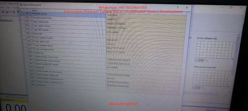
Old firmware (e.g., 15.01.00) has known bugs affecting voltage detection. Referring to Engineer software diagnostics, if the control card (E84ABCTC0000SN0) does not match the power section (E84ABNDT134VN0), voltage readings will deviate.

Through this analysis, users can preliminarily determine the fault type. For instance, if accompanied by Su02 (Phase Missing), prioritize checking the power supply; if only LU is present, focus on internal hardware. The manual recommends using a multimeter to measure the actual voltage and comparing it with the C00053 reading to distinguish sensor faults.

Diagnostic Methods

Accurate diagnosis is a prerequisite for troubleshooting. The Lenze 8400 BaseLine D provides multi-layer diagnostic tools, referring to chapters “Diagnostics & error management” on pages 142-163 of the manual.

1. Keypad and LED Check

Observe the screen upon startup. If “LU” is displayed or C00053 is low, press the navigation key to enter Menu -5- (Diagnostics) to view the C00160 Logbook and C00165 Error ID. LEDs: Red flashing indicates Trouble (auto-recoverable); solid red indicates Fault. Page 19 of the manual’s LED status table aids quick judgment.

2. Parameter Reading

Use the keypad or Engineer software to read key parameters:

  • C00053 (DC-bus voltage): Should be approx. 565 V.
  • C00054 (Motor current): Abnormalities indicate load issues.
  • C00064 (Ixt Utilization): >80% suggests overload.
  • Set C00517/2 = 53 to display voltage constantly on the screen for monitoring.
Engineer Software for lenze drive

3. Engineer Software Diagnosis

Connect a PC to the X6 USB port (pages 32-34 of the manual). View logs, signal flow charts, and oscilloscope traces online. The Diagnostics tab shows error history; if LU is accompanied by PS02 (Invalid Parameter), it indicates a configuration issue. The software can simulate operation to test voltage response.

4. Hardware Measurement

After powering down, use a multimeter to measure the X100 input voltage (three-phase balance <5% deviation) and DC-bus terminals (+UG/-UG, note high voltage >500 V). If manual measurement is normal but the screen reads 0 V, suspect a voltage sensor fault (control board issue).

5. Logbook Analysis

C00160 records events, such as “LU at timestamp XX,” combined with C00137 (Device Status) to determine the trigger timing. If it occurs at startup, check Flying Start (C00140); if during operation, check load fluctuations.

6. Auxiliary Tools

Use an EPM Programmer to copy memory module data (page 15 of the manual) and compare old and new configurations. An external oscilloscope can monitor the input waveform to detect harmonics or transients.

The diagnostic process should proceed from simple to complex to avoid blind disassembly. The manual emphasizes safety: power down for 10 seconds and wear insulating gear before operating. If diagnosis confirms hardware damage, professional repair is required.

Troubleshooting Steps

Based on diagnostic results, troubleshooting undervoltage faults proceeds step-by-step. Pages 155-156 (Reset Methods) and 158 (Error Handling) of the manual provide guidance.

  1. Initial Reset
    Press the STOP button, then RUN to enable the controller. Set C00002/19 = 1 to reset the error. If it recovers automatically, monitor the voltage for stability.
  2. Power Supply Check and Repair
    Measure input voltage to ensure three-phase balance. Replace damaged cables or filters. Page 108 of the manual recommends enabling Main Phase Monitoring (C00565 = 1); if Su02 is triggered, check circuit breakers.
  3. Parameter Optimization
    Load Lenze default settings (C00002/1 = 1) and save (C00002/7 = 1). Enable Flying Start (C00140 = 1) to handle load issues. Adjust C00600 to the appropriate response mode.
  4. Hardware Replacement
    If the control board is faulty, swap back the original board for testing. Check the capacitor bank for bulging or leakage. Page 15 (Memory Module Handling): Import data (C00002/12 = 1).
  5. Load Adjustment
    Extend acceleration time (C00040) to reduce starting shock. Add an external choke to stabilize the input.
  6. Firmware Update
    Download the latest firmware using Engineer, then reset parameters after updating.
  7. Test Verification
    After troubleshooting, run no-load to monitor C00053. Conduct load tests to ensure the fault does not recur.

Steps should be logged to avoid repeating faults. If ineffective, contact Lenze support with the serial number and logs.

Preventive Measures

Preventing undervoltage faults lies in design and maintenance. Page 26 of the manual emphasizes regular inspections.

  1. Design Optimization
    Consider grid quality during sizing; use UPS or voltage stabilizers. The manual’s project planning section suggests a 20% power margin.
  2. Regular Maintenance
    Check connections monthly and clean ventilation. Monitor Ixt and temperature (C00061 < 80°C).
  3. Parameter Monitoring
    Enable auto-save (C00141 = 1) and set alarm thresholds.
  4. Training and Documentation
    Operators should be familiar with display messages on page 20 of the manual.
  5. Backup Strategy
    Regularly export parameters to a PC.

These measures can minimize the fault rate.

Case Studies

Case 1: LU Fault in Factory Conveyor System

  • Diagnosis: Input phase missing.
  • Solution: Replaced cable and reset.
  • Prevention: Added a phase sequence relay.

Case 2: 0 V Reading After Control Board Replacement

  • Diagnosis: Parameter incompatibility.
  • Solution: Imported EPM data.
  • Prevention: Verified board model compatibility.

Case 3: Recurring Fault in High-Temperature Environment

  • Diagnosis: Capacitor aging.
  • Solution: Replaced module and improved ventilation.
  • Prevention: Installed cooling fans.

These cases demonstrate practical applications.

Conclusion

While the Lenze 8400 BaseLine D undervoltage fault is common, it can be resolved efficiently through systematic diagnosis and troubleshooting. This guide provides comprehensive guidance to enhance equipment stability.

Posted on

Analysis and Optimization Strategies for SLP Code on Tianchuan Frequency Inverters: Achieving Efficient Constant Pressure Water Supply

Introduction

In modern industrial and civil water supply systems, constant pressure water supply technology is highly favored for its ability to stabilize water pressure, improve water quality, and effectively save energy. Tianchuan frequency inverters, as high-performance water supply control devices, are widely used in various water supply scenarios. However, during use, users may encounter situations where the frequency inverter displays the SLP code, which is often related to the sleep function in constant pressure water supply mode. This article will delve into the meaning of the SLP code on Tianchuan frequency inverters, the reasons for its appearance, and optimization strategies to help users better understand and utilize frequency inverters for efficient and energy-saving constant pressure water supply.

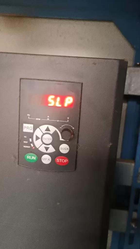
SLP status

1. Explanation of the SLP Code

1.1 Basic Definition of the SLP Code

The SLP code is a status indicator on Tianchuan frequency inverters in constant pressure water supply mode, representing that the frequency inverter is currently in a “sleep” state. When the water supply system pressure reaches the set value and there is no water demand for a certain period, the frequency inverter automatically reduces the operating frequency or even stops to reduce unnecessary energy consumption. At this time, the SLP code is displayed on the frequency inverter’s operation panel, indicating that the system has entered an energy-saving mode.

1.2 Energy-Saving Principle of the Sleep Function

The sleep function is an important energy-saving technology for frequency inverters in constant pressure water supply systems. By continuously monitoring the system pressure, when the pressure reaches the set value and there is no water demand for a certain period, the frequency inverter automatically adjusts its operating state, reducing the motor’s running time and thus lowering electricity consumption. This intelligent adjustment mechanism not only helps save energy but also extends the equipment’s service life and reduces maintenance costs.

2. Causes of the SLP Code Appearing

2.1 System Pressure Reaches the Set Value

When the water supply system pressure reaches the target pressure value set by the frequency inverter and there is no water demand for a certain period, the frequency inverter automatically triggers the sleep function and displays the SLP code. This is a normal energy-saving phenomenon, indicating that the system is operating effectively.

2.2 Improper Setting of Sleep-Related Parameters

The conditions for the frequency inverter to enter the sleep state are not only related to the system pressure but also influenced by parameters such as sleep frequency and sleep delay time. If these parameters are set unreasonably, it may cause the frequency inverter to frequently enter or exit the sleep state, affecting system stability and energy-saving effects.

2.3 Pressure Sensor Failure or False Alarms

The system pressure sensor is an important basis for the frequency inverter to determine whether to enter the sleep state. If the sensor fails or is improperly set, it may cause the frequency inverter to misjudge the system pressure, leading to incorrect display of the SLP code or inability to enter the sleep state normally.

2.4 System Leakage or Changes in Water Consumption Patterns

System leakage or changes in user water consumption patterns may also cause the frequency inverter to frequently display the SLP code. For example, pipeline leakage can cause the system pressure to continuously drop, preventing the frequency inverter from maintaining a stable sleep state. Sudden changes in user water consumption patterns, such as a large amount of water consumption in a short period, may also prevent the frequency inverter from adjusting its operating state in a timely manner.

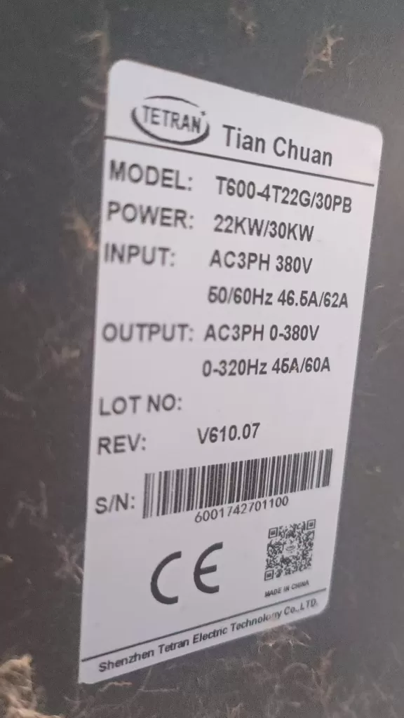
T600-4T22G/30 PB TETRAN INVERTER

3. Optimization Strategies for SLP Code Issues

3.1 Reasonable Setting of Sleep-Related Parameters

3.1.1 Sleep Frequency

The sleep frequency is the frequency threshold for the frequency inverter to enter the sleep state. Based on the actual needs of the system, set the sleep frequency reasonably to avoid it being too high or too low. An excessively high sleep frequency may prevent the frequency inverter from effectively saving energy, while an excessively low sleep frequency may affect the system’s response speed. For example, increasing the sleep frequency from the original 20Hz to 25Hz can ensure that the frequency inverter exits the sleep state only after the system pressure has stabilized and dropped.

3.1.2 Sleep Delay Time

The sleep delay time is the time parameter for the frequency inverter to enter the sleep state after reaching the sleep frequency and experiencing no water demand for a certain period. Based on the system’s water consumption habits, set the sleep delay time reasonably to prevent the frequency inverter from frequently entering the sleep state due to short-term absence of water demand. For example, extending the sleep delay time from the original 30 seconds to 1 minute can improve system stability.

3.1.3 Water Supply Sleep Tolerance

The water supply sleep tolerance is the tolerance range for the system pressure near the set value. Appropriately increasing the water supply sleep tolerance can reduce the frequency of the frequency inverter entering and exiting the sleep state due to pressure fluctuations, improving system stability. For example, increasing the water supply sleep tolerance from the original 5% to 10% can effectively reduce the frequency inverter’s frequent adjustments.

3.2 Inspect and Calibrate the Pressure Sensor

Ensure that the system pressure sensor is working properly and can accurately reflect the system pressure. Regularly calibrate and maintain the pressure sensor to prevent the frequency inverter from misjudging the system pressure due to sensor failure or false alarms. If abnormal sensor readings are detected, replace or adjust the sensor promptly.

3.3 Optimize System Design and Maintenance

3.3.1 Check for System Leakage

Regularly inspect the water supply system for leakage and promptly repair any leaks to ensure stable system pressure. Leakage not only causes the frequency inverter to frequently display the SLP code but also results in water waste and equipment damage. Through regular inspections and maintenance, leakage issues can be effectively prevented.

3.3.2 Analyze Water Consumption Patterns and Adjust Strategies

Based on changes in user water consumption patterns, adjust the operating strategy of the frequency inverter in a timely manner. For example, start the frequency inverter in advance before peak water consumption periods to ensure stable system pressure. During low water consumption periods, reasonably set sleep parameters to achieve energy-saving operation. By intelligently analyzing water consumption patterns, the operating efficiency of the frequency inverter can be further optimized.

3.4 Upgrade Frequency Inverter Software and Firmware

With continuous technological advancements, frequency inverter manufacturers continuously optimize product software and firmware to improve system stability and energy-saving effects. Regularly check and upgrade the software and firmware versions of the frequency inverter to ensure that the equipment is always in the best operating state. Read the upgrade instructions carefully before upgrading to ensure a smooth process.

4. Practical Case Analysis

4.1 Case Background

A residential community uses a Tianchuan frequency inverter for constant pressure water supply control. Recently, users have reported that the frequency inverter frequently displays the SLP code and sometimes fails to respond promptly to water demand. Preliminary inspections revealed that the system pressure sensor is working properly, but the sleep-related parameters are set conservatively.

4.2 Problem Analysis

  • Low Sleep Frequency Setting: The frequency inverter exits the sleep state as soon as the system pressure drops slightly, preventing effective energy savings.
  • Short Sleep Delay Time: The frequency inverter enters the sleep state shortly after a brief absence of water demand, affecting the system’s response speed.
  • Small Water Supply Sleep Tolerance: Slight pressure fluctuations cause the frequency inverter to frequently enter and exit the sleep state.

4.3 Solution

  • Adjust Sleep Frequency: Increase the sleep frequency from the original 20Hz to 25Hz to ensure that the frequency inverter exits the sleep state only after the system pressure has stabilized and dropped.
  • Extend Sleep Delay Time: Extend the sleep delay time from the original 30 seconds to 1 minute to prevent the frequency inverter from frequently entering the sleep state due to short-term absence of water demand.
  • Increase Water Supply Sleep Tolerance: Increase the water supply sleep tolerance from the original 5% to 10% to reduce the frequency of the frequency inverter adjusting its operating state due to pressure fluctuations.

4.4 Implementation Effect

After implementing the above adjustments, the frequency inverter’s display of the SLP code significantly decreased, and the system’s response speed improved, enhancing the user’s water consumption experience. At the same time, since the frequency inverter can effectively enter the sleep state during periods of no water demand, the overall energy consumption of the system also decreased.

5. Conclusion and Outlook

5.1 Conclusion

The appearance of the SLP code on Tianchuan frequency inverters is a normal energy-saving phenomenon in constant pressure water supply mode. However, if the frequency inverter frequently displays the SLP code or fails to respond promptly to water demand, it may be related to factors such as improper setting of sleep-related parameters, pressure sensor failure, or system leakage. By reasonably setting sleep parameters, inspecting and calibrating the pressure sensor, optimizing system design and maintenance, and upgrading frequency inverter software and firmware, SLP code-related issues can be effectively resolved, achieving efficient and energy-saving constant pressure water supply.

5.2 Outlook

With the continuous development of intelligent water supply technology, future frequency inverters will become more intelligent and automated. By introducing advanced control algorithms and sensor technologies, frequency inverters will be able to more accurately judge system status and user demand, achieving more precise and efficient constant pressure water supply control. At the same time, with the popularization and application of IoT technology, frequency inverters will also realize functions such as remote monitoring and fault diagnosis, further improving the reliability and maintenance efficiency of water supply systems. Users can expect more intelligent, convenient, and energy-saving water supply solutions, bringing more convenience and benefits to daily life and industrial production.

Posted on

In-depth Analysis of Rhymebus RM6 Series Inverters: From Principles to Troubleshooting — Using SC Fuse Open Protection as an Example

Introduction

In the field of modern industrial automation and energy saving, the AC Variable Frequency Drive (VFD) has become the core equipment for motor speed control. By changing the power frequency and voltage, it achieves precise control of three-phase asynchronous motors, significantly improving system efficiency, reducing energy consumption, and providing rich protection functions.

Rhymebus Corporation, a professional manufacturer with over 35 years of experience in power electronics, has seen its RM6 series inverters widely applied in textiles, food processing, fluid machinery, HVAC (Heating, Ventilation, and Air Conditioning), and elevators due to their reliable performance, comprehensive protection mechanisms, and flexibility for various applications.

The RM6 series adopts advanced IGBT control technology and digital signal processing, with an output frequency range of 0.1~400Hz. It supports V/F control mode, PID closed-loop regulation, RS-485 Modbus communication, and other functions. The power range covers 0.5HP to several hundred HP, with voltage levels including 200V and 400V series. The overload capacity is divided into heavy-duty (150% for 1 minute) and light-duty (120% for 1 minute), suitable for constant torque and variable torque loads.

This article uses the common user fault code “SC” (Fuse Open Protection) as a starting point to systematically analyze the structure, working principle, installation and debugging, parameter optimization, and fault diagnosis of the RM6 series inverters, providing practical technical guidance to help engineers and maintenance personnel improve equipment reliability and service life.

Structure and Working Principle of the RM6 Series Inverter

The RM6 series inverter adopts the classic three-phase rectifier-inverter topology, with the main components including:

  1. Rectifier Section: Input three-phase AC 380-480V (or 200V series) is rectified by an uncontrolled diode bridge, outputting a DC bus voltage (approximately 540V DC for 380V input).
  2. Filter Section: The DC link capacitor smooths the ripple to provide a stable DC voltage. Some models support external DC reactors (DCL) to suppress harmonics.
  3. Inverter Section: The core uses an IGBT power module to generate three-phase variable frequency/voltage output (U, V, W terminals) through SPWM (Sine Wave Pulse Width Modulation) or SVPWM to drive the motor.
  4. Control Section: Based on DSP or MCU, it integrates analog inputs (0-10V/4-20mA), multi-function digital terminals, PID controller, and RS-485 interface.
  5. Protection Circuit: Includes hardware/software protection such as Overcurrent (OC), Overvoltage (OE), Undervoltage (LE1), Overheat (OH), Ground Fault (GF), and Fuse Open (SC).

Working Principle and Control Logic
The working principle is based on Voltage/Frequency (V/F) control: maintaining a constant V/F ratio to ensure stable motor magnetic flux, avoiding field weakening or saturation. The RM6 supports multiple V/F curves (linear, energy-saving, square law, etc.) and integrates the following key functions:

  • Slip Compensation (Parameter F_050)
  • AVR (Automatic Voltage Regulation, F_093)
  • Stall Prevention (F_070~F_074) to prevent overcurrent or stalling during acceleration, constant speed, or deceleration.

Energy-Saving Application Features
The RM6 is particularly prominent in energy-saving applications:

  • For square torque loads such as fans and water pumps, it reduces output voltage during light loads to reduce copper and iron losses, achieving 30%-60% energy savings.
  • The built-in PID function (F_153~F_195) supports constant pressure/current/temperature/flow control, suitable for air conditioning cooling towers and constant pressure water supply systems.
 a typical three-phase VFD wiring schematic, showing the connection of input R/S/T, output U/V/W, and ground PE. The actual RM6 series is similar

(The image above is a typical three-phase VFD wiring schematic, showing the connection of input R/S/T, output U/V/W, and ground PE. The actual RM6 series is similar.)

Installation and Wiring Specifications for the RM6 Series

Correct installation and wiring are the first steps to avoiding faults (such as SC). According to the RM6 manual:

Environmental and Heat Dissipation Requirements

  • Environment: Install on a metal fireproof surface. Ambient temperature <50°C (inside the control panel), humidity <90%RH, and no corrosive gases. IP20 protection rating; avoid direct contact with live parts.
  • Spacing: Vertical spacing >10cm, left/right/rear >5cm.
  • Heat Dissipation: For forced air-cooled models, ensure the air duct is unobstructed; fans require regular maintenance.

Power and Wiring Specifications

  • Circuit Breaker: Configure MCCB or NFB at the input (rated current 1.5~2 times the inverter’s rated current).
  • Reactor: Connect an external ACL (AC Reactor) when the power supply capacity is >10 times the inverter’s rated capacity or >500kVA to suppress harmonics.
  • Grounding: The PE terminal must be reliably grounded. Connect the motor housing to the inverter PE using 75°C copper wire; the cross-sectional area depends on the model (e.g., at least 2.5mm² for a 400V 17A model).
  • Output Side: U/V/W connect directly to the motor.
    • If cable length >30m, it is recommended to add an output ACL to suppress dV/dt.
    • Prohibited: Do not install contactors or capacitors on the output side.
  • Control Wires: Use shielded twisted pairs separated from the main circuit wiring; length <20m (for UP/DOWN control).

Pre-energization Check
Wiring errors (such as output short circuits or poor grounding) are the main causes of SC faults. The post-installation process:

  1. Check DC bus voltage with no load.
  2. Wait for the CHARGE light to turn off (5~20 minutes) and ensure the voltage between P/+ and N/- is <25V before operating.
  3. Then connect the motor for testing.
PWM VFD working principle diagram, showing the SPWM generation process; RM6 uses similar technology

(PWM VFD working principle diagram, showing the SPWM generation process; RM6 uses similar technology.)

Parameter Settings and Optimization Strategies

The RM6 series has rich parameters (F_000~F_220+), with factory defaults suitable for heavy-duty mode.

Key Parameter Classification

CategoryParameter CodeFunction Description
Basic SettingsF_001Start Command: 0=Terminal, 3=Keypad
F_002Frequency Command: 1=Analog Input
F_031Max Frequency: 60/50Hz
F_019/F_020Accel/Decel Time: 5~30s depending on load
Motor ParametersF_048Motor Rated Current
F_051Number of Poles
F_046Motor Overload Protection Enable
ProtectionF_070~F_074Stall Prevention Level: Accel 170%, Constant 160%
F_098Ground Fault Detection
F_116Auto Reset Count
PID ControlF_153=1Closed Loop Mode
F_155~F_157P/I/D Gains
F_125~F_152Feedback Source, Setpoint Source
AdvancedF_081Carrier Frequency: 0~15kHz (balance noise & efficiency)
F_211Heavy/Light Duty Switch

Optimization Suggestions

  • Fans/Pumps: Enable energy-saving mode (F_102=1) and reduce stall prevention level to 80%.
  • Heavy Machinery (e.g., extruders): Extend acceleration time to avoid OC/SC triggering.
  • Anti-misoperation: Lock parameters (F_092) to prevent accidental changes.

SC Fault Code Details: Fuse Open Protection

SC FAULT

The RM6 series fault display uses the KEYPAD panel. The SC code corresponds to “Fuse Open Protection” (保險絲開路保護).

Fault Meaning
The internal fuse has blown or the IGBT module has failed, causing the main circuit to be interrupted. The manual specifies that causes include an internal fuse open circuit or damage to the IGBT power module.

Common Trigger Causes

  1. Output Short Circuit: Short circuit between U-V, V-W, W-U, or any phase to ground (cable damage, motor winding failure, wiring error).
  2. Ground Leakage: Insulation resistance <100MΩ (tested with a 500V megger), causing high current.
  3. IGBT Breakdown: Overvoltage spikes, overheating, aging, or manufacturing defects cause IGBT short circuits, instantly blowing the fuse with high current.
  4. External Overload/Impact: Load jamming during startup, motor stall, or frequent starts/stops.
  5. Improper Wiring: Mixing up input/output or lack of grounding.

Diagnosis and Troubleshooting Steps (High voltage operation requires professionals)

  1. Power Off and Discharge: Turn off power, wait for the CHARGE light to go out (5~20 minutes), and measure voltage between P/+ and N/- to ensure it is <25V.
  2. External Inspection:
    • Remove U/V/W cables.
    • Use a multimeter to measure resistance between the three phases (balanced, low value indicates a short).
    • Perform insulation test to ground (requirement ≥100MΩ).
    • Use a megger to test motor windings.
  3. Reset Attempt: Power on again and press the RESET key.
    • If SC disappears, it may have been a transient disturbance.
    • If it persists, proceed to hardware fault investigation.
  4. Internal Diagnosis:
    • Check the internal fuse (if accessible, test continuity with a multimeter).
    • IGBT module testing requires professional tools (testing gate-emitter resistance, collector-emitter withstand voltage).
  5. Repair:
    • Replace the fuse (must follow manual specifications, e.g., Class RK5/T type).
    • IGBT damage usually requires returning the unit to the factory for repair (module replacement cost is high).
  6. Prevention: Regular insulation testing, adding output reactors, enabling GF detection (F_098=1), and real-time output current monitoring.

Manual suggestion: For SC faults, please contact customer service for repair; avoid disassembling the unit yourself.

(IGBT module example; the RM6 series inverter bridge uses similar power devices, and damage often causes SC.)

Common Fault Prevention and Maintenance Practices

  • Daily Inspection: Monitor panel display (current, temperature, DC voltage) and check for dust on fans and heat sinks.
  • Regular Maintenance: Perform annual insulation tests, tighten terminals, and clean filters.
  • Advanced Application: Integrate Modbus monitoring (address 0-255, baud rate 4800~38400bps) for remote fault diagnosis.
  • Energy-Saving Case: In HVAC constant pressure water supply systems, using RM6 PID + multi-pump switching can achieve an energy-saving rate of over 40%.

Conclusion

The RM6 series inverter is a reliable choice for industrial energy saving due to its comprehensive protection, ease of use, and high cost-performance ratio. Although the SC fault is a hardware-level issue, most cases can be avoided or quickly located through standardized installation, careful diagnosis of external short circuits, and timely maintenance.

Understanding its principles and protection mechanisms not only solves immediate problems but also enhances the stability and lifespan of the entire system. It is recommended that users record parameters (Appendix F table) and perform regular data backups.

Posted on

Deep Analysis and Comprehensive Troubleshooting Guide for ALE08 Fault on DPSON DSL200P Servo Drives

Introduction

In the realm of industrial automation, servo drives serve as the critical “muscle” and “brain” of motion control systems, dictating the precision, speed, and stability of machinery. The DPSON DSL200P series, known for its cost-effectiveness and reliability, is widely deployed in packaging machinery, CNC lathes, conveyor systems, and printing equipment. However, like all sophisticated electronic devices, they are susceptible to specific operational faults.

One of the most frequent and disruptive alarms encountered by engineers is ALE08 (Position Deviation Counter Overflow). When this fault occurs, the drive halts the motor abruptly to prevent mechanical damage or motor burnout. If not diagnosed correctly, troubleshooting can be time-consuming, leading to significant production downtime.

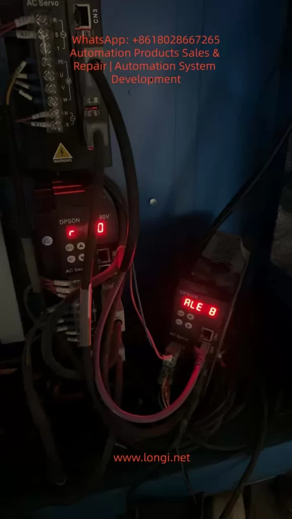
ALE 8

This article provides an exhaustive technical analysis of the ALE08 fault. We will dissect the underlying control logic, categorize root causes into mechanical, electrical, and parametric domains, provide a step-by-step diagnostic workflow, analyze real-world case studies, and outline preventive maintenance strategies. This guide is designed for maintenance engineers, system integrators, and automation students seeking a deep understanding of servo dynamics.


I. The Principle of ALE08: Understanding Position Deviation

To effectively troubleshoot ALE08, one must first understand the Closed-Loop Position Control architecture inherent to servo systems.

1. The Control Loop Logic

A servo system operates on a feedback loop:

  1. Command Input: The host controller (PLC or Motion Card) sends a stream of Command Pulses (representing position or speed) to the drive.
  2. Feedback Input: The servo motor’s encoder sends Feedback Pulses back to the drive, reporting the actual rotor position.
  3. Deviation Calculation: The drive’s DSP (Digital Signal Processor) continuously subtracts the Feedback Pulse count from the Command Pulse count. The result is the Position Deviation (or Position Error).
  4. Correction: Using PID (Proportional-Integral-Derivative) algorithms, the drive adjusts the output voltage/current to the motor to minimize this deviation to zero.

2. The Position Deviation Counter

The Position Deviation Counter is a specific register within the drive’s memory (typically a 16-bit or 32-bit signed integer). It acts as a “bucket” that accumulates the difference between where the motor should be and where it is.

The Overflow Mechanism:
Every servo drive has a maximum limit for this counter (e.g., ±32,767 for a 16-bit system). If the motor fails to follow the command—due to being blocked, lack of torque, or signal loss—the deviation value accumulates rapidly. Once this value exceeds the register’s limit, an overflow occurs. The drive interprets this as a critical failure (the system has lost control of the axis) and triggers ALE08, cutting power to the motor (coast stop or decelerated stop) to protect the machinery.


II. Root Cause Analysis: The Three Domains of Failure

Based on field data and the DSL200P technical manual, the causes of ALE08 can be systematically categorized into three primary domains: Mechanical LoadCommand Signal, and Motor/Drive System.

Domain A: Mechanical Load Anomalies (The Most Common Culprit)

This accounts for approximately 60% of ALE08 cases. The issue is not electronic; it is physical. The motor simply cannot generate enough torque to overcome the resistance.

  1. Excessive Load/Jamming:
    • Scenario: A conveyor belt gets stuck on a debris, or a packaging machine hopper gets clogged.
    • Physics: The load torque exceeds the motor’s peak torque (e.g., a 750W motor typically offers ~2.39 N·m rated torque, but the instantaneous load demands 5 N·m). The motor stalls, but the controller keeps sending pulses, causing the deviation counter to max out instantly.
  2. Transmission Component Failure:
    • Ball Screw/Lead Screw: Worn nuts, lack of lubrication, or bent shafts increase friction exponentially.
    • Belt Drive: Belt snapping, severe slippage, or incorrect tension.
    • Bearings: Seized bearings due to contamination or lack of grease.
    • Couplings: Failure of the flexible element (spider) in the coupling, disconnecting the motor from the load mechanically while the encoder still reports “zero movement.”
  3. Foreign Object Intrusion: Metal chips, plastic fragments, or dust entering the screw/nut interface creates a physical barrier.
  4. Misalignment: The motor axis and the load axis are not concentric, creating binding forces (radial load) that the motor bearings cannot handle.

Domain B: Command Pulse Anomalies (The “Confused” Drive)

If the drive receives incorrect instructions, it cannot calculate the deviation correctly, or the deviation accumulates erroneously.

  1. Controller/Source Issues:
    • Frequency Mismatch: The controller outputs pulses at 300kHz, but the DSL200P is rated for a maximum of 200kHz. The drive misses pulses, leading to calculation errors.
    • Electrical Interference (EMI): Noise from nearby VFDs or heavy machinery couples into the pulse line, creating “ghost pulses” or dropping real pulses.
    • Hardware Failure: A blown transistor in the controller’s output module.
  2. Wiring & Connection Faults:
    • Loose Terminals: Oxidation or vibration loosening screws on PUL+, PUL-, or SIGNAL GND.
    • Cable Damage: Broken shielding or shorted cores in the encoder/pulse cable.
    • Grounding Loops: Improper grounding causing reference voltage shifts.
  3. Parameter Mismatches:
    • Electronic Gear Ratio (EGR): If the mechanical reduction is 5:1 but the parameter is set to 1:1, the drive expects the motor to turn 5x faster than it physically can, causing immediate overflow.
    • Pulse Equivalent: Incorrect settings for “pulses per millimeter” lead to scaling errors in the deviation calculation.
    • Signal Type: Controller sends Differential Line Driver (RS422) signals, but the drive is set to NPN/Open Collector mode.

Domain C: Motor and Drive Output Failures (The “Weak” System)

Even with a perfect command and a free mechanical load, the system might fail to execute.

  1. Motor Faults:
    • Winding Short/Open: The motor generates zero torque.
    • Encoder Failure: A dirty code disk or broken cable causes the drive to lose position feedback. The drive thinks the motor isn’t moving (even if it is vibrating) and increases current, eventually triggering an error or overflow as it fights “phantom” resistance.
    • Brake Issues: If the motor has a holding brake that fails to release, the motor cannot turn.
  2. Drive Hardware Faults:
    • IGBT Module Damage: One phase of the inverter is dead, resulting in single-phasing. The motor hums but produces insufficient torque.
    • Output Line Break: The U/V/W power cable to the motor is severed.
    • Current Limit Settings: The “Torque Limit” parameter is set too low (e.g., 20% of rated current), physically preventing the motor from moving a heavy load.
  3. Incorrect Motor Parameters:
    • Auto-Tuning Failure: The drive has not been “tuned” to the specific motor inertia.
    • Mismatched Specs: The drive is configured for a 400W motor, but a 750W motor is attached (or vice versa), leading to current saturation.

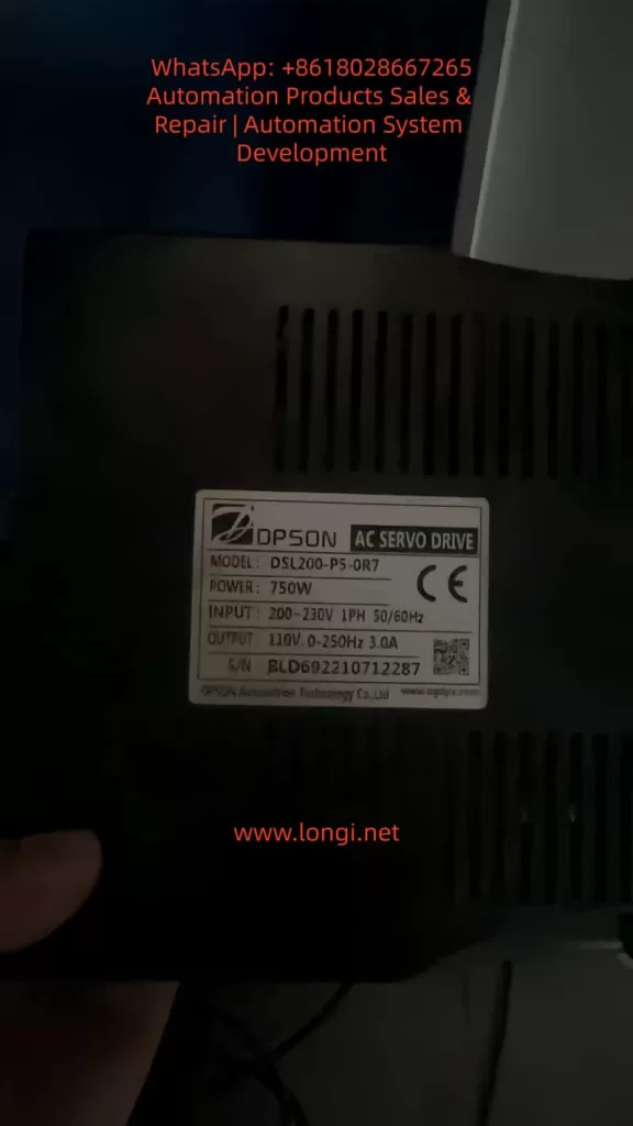
DSL200-P5-0R7

III. Systematic Troubleshooting Workflow

Follow this “Outside-In” approach to isolate the fault efficiently. Safety First: Disconnect main power before physical inspection.

Step 1: Mechanical Isolation (The “Hand Test”)

Goal: Determine if the load is physically free.

  1. Power Down: Turn off the main breaker and wait for the drive LEDs to extinguish (capacitors discharge).
  2. Manual Rotation:
    • Direct Drive: Try to turn the motor shaft by hand. It should offer some resistance (magnetic detent) but turn smoothly. If it is locked solid, the motor bearings are seized, or the brake is engaged.
    • Belt/Screw Drive: Disconnect the coupling (if possible) and turn the motor side. Then turn the load side.
      • Motor turns, Load does not: The jam is in the transmission (screw, bearing, gearbox). Inspect for chips or lack of lube.
      • Neither turns: The jam is at the load end (conveyor, axis).
  3. Inspection: Visually check for broken belts, disconnected couplers, or obvious obstructions.

Step 2: Signal Verification (The “Oscilloscope Test”)

Goal: Verify the integrity of the Command Pulses.

  1. Reconnect Power: Keep the motor disconnected (or hold the brake) to prevent movement.
  2. Measure: Connect an oscilloscope to the drive’s PUL+ and PUL- terminals (referenced to SIGNAL GND).
  3. Analyze Waveform:
    • Shape: Look for clean square waves. “Rounded” edges or “stair-stepping” indicates weak drive circuitry or cable capacitance issues. “Spikes” indicate noise.
    • Amplitude:
      • Differential (RS422): Should be ~2V to 5V peak-to-peak.
      • Open Collector (NPN): Should swing from 0V to 24V (or 5V depending on the system).
    • Frequency: Command a move (e.g., 10kHz). Does the scope read 10kHz? If it reads 5kHz or 15kHz, the controller or cabling is faulty.
  4. Check Shielding: Ensure the cable shield is grounded at both ends (Controller and Drive) for high-frequency noise immunity.

Step 3: Parameter & Configuration Audit

Goal: Ensure the “Software” matches the “Hardware”.

Access the DSL200P parameter list (usually via keypad or software). Verify:

  • PA01 (Pulse Type): Matches wiring (Differential vs. Open Collector).
  • PA02 (Electronic Gear Ratio): Numerator/Denominator matches mechanical reduction (e.g., 1/5 for a 5:1 reducer).
  • PA03 (Pulse Equivalent): Correct value for the machine (e.g., 0.001mm/pulse).
  • PA05 (Motor Model): Matches the physical motor tag.
  • PA10 (Torque Limit): Is it set to 100% or higher? (Sometimes set low for safety testing).

Step 4: Electrical Component Testing

Goal: Test the Motor and Drive power stage.

  1. Motor Insulation & Resistance:
    • Use a Megger (insulation tester) to check U/V/W to Ground (should be >100MΩ).
    • Use a multimeter to measure U-V, V-W, W-U resistance. They should be balanced (e.g., all ~1.5Ω). An open circuit (OL) or short circuit (0Ω) indicates burnt windings.
  2. Encoder Check:
    • Rotate the motor shaft by hand slowly.
    • Monitor the diagnostic screen (or use a frequency counter) for A/B/Z phase pulses. They should increment/decrement smoothly without dropping counts.
  3. Drive Output (IGBT):
    • Warning: High Voltage. With power on (no run command), measure DC bus voltage (across P/+ and N/-). It should be ~1.41x the input AC voltage (e.g., 320VDC for 220VAC input).
    • If the DC bus is low or zero, the rectifier bridge is blown.

IV. Case Studies: Real-World Diagnostics

Case 1: The “Invisible” Jam in a Packaging Machine

  • Symptom: Intermittent ALE08 on a sealing bar axis. Manual rotation felt “heavy” but possible.
  • Investigation: Mechanical inspection revealed no broken parts. The ball screw was clean. However, the linear guide rails were covered in hardened glue residue from a previous product run.
  • Resolution: Cleaning the rails and re-greasing solved the issue. The friction coefficient had increased just enough to exceed the motor’s torque margin during high-speed moves.

Case 2: The Ground Loop Interference

  • Symptom: ALE08 occurred only when a large 5kW spindle motor started nearby.
  • Investigation: Oscilloscope revealed massive noise spikes on the pulse line coinciding with the spindle start-up. The pulse cable was routed in the same trunking as the 220V spindle power cable.
  • Resolution: Re-routing the pulse cable 30cm away from the power cable and installing a ferrite ring (magnetic bead) on the pulse line at the drive end eliminated the noise.

Case 3: Incorrect Electronic Gear Ratio

  • Symptom: ALE08 immediately upon starting a “Jog” command, even with the motor unloaded (coupling removed).
  • Investigation: The machine was a direct drive (1:1), but the parameter “Electronic Gear” was set to 2:1 from a previous machine setup. The drive was commanding the motor to move twice as fast as the encoder was reporting, causing instant overflow.
  • Resolution: Resetting the Electronic Gear Ratio to 1:1 cleared the fault.

V. Prevention and Maintenance Strategy

“An ounce of prevention is worth a pound of cure.” To minimize ALE08 occurrences:

  1. Mechanical PM Schedule:
    • Weekly: Lubricate screws and rails.
    • Monthly: Check belt tension and coupler set screws.
    • Quarterly: Clean debris from machine tracks.
  2. Electrical Best Practices:
    • Use shielded twisted-pair cables for encoders and pulses.
    • Ground the shield at both ends (for servo drives, this is usually preferred over single-point grounding to shunt high-frequency noise).
    • Separate power cables (220V/380V) from signal cables (24V/5V).
  3. Parameter Management:
    • Perform a “Backup” of parameters to a USB or PC after every commissioning.
    • Document the mechanical reduction ratios and pulse equivalents physically on the machine.
  4. Operator Training:
    • Train operators to recognize the sound of a “stalling” motor (a loud hum) and to hit the E-Stop immediately rather than resetting the drive repeatedly (which can burn the motor).

VI. Common Pitfalls and Safety Warnings

  1. The “Reset” Trap: Do not simply press “Reset” multiple times. If the mechanical load is jammed, resetting will cause the drive to try to push again, potentially overheating the motor windings or stripping gears. Find the root cause first.
  2. Ignoring the Encoder: A dirty encoder is a silent killer. If the feedback is lost, the drive assumes the motor is stationary and ramps up current to max, often tripping “Overcurrent” (ALE02) before “Overflow” (ALE08), but sometimes causing ALE08 if the error accumulates subtly.
  3. Safety: Always assume the motor can move. Secure the load with blocks or jacks before working under it, even if the drive is off (gravity can move vertical axes).

Conclusion

The ALE08 (Position Deviation Counter Overflow) fault on the DPSON DSL200P is a protective mechanism indicating a loss of synchronization between the commanded position and the actual position. While it signals a stop in production, it prevents catastrophic mechanical failure.

By understanding the closed-loop control logic, systematically isolating the problem into mechanical, signal, and parametric categories, and utilizing tools like oscilloscopes and multimeters, engineers can drastically reduce troubleshooting time. Remember that 70% of ALE08 faults are mechanical (friction/jamming), 20% are wiring/interference, and only 10% are drive/motor hardware failures.

Mastering the diagnosis of ALE08 is not just about fixing a single error code; it is about mastering the dynamics of motion control. With the guidelines provided in this article, maintenance personnel can transform from reactive “part changers” into proactive system diagnosticians, ensuring higher uptime and reliability for industrial automation systems.

Posted on

Analysis and Handling of E0020 Contactor Fault in WISCO South E-CONVERT 5 Series Inverter

Introduction

In the field of modern industrial automation, inverters, as the core equipment for motor control, play a crucial role in ensuring production safety and improving equipment utilization. The E-CONVERT 5 series inverter launched by WISCO South (Wuhan) Automation Co., Ltd. has gained widespread market recognition for its high performance, high reliability, and rich functionality. However, during actual operation, the E0020 contactor fault, as a relatively common type of fault, poses a threat to the normal operation of the equipment. This article will provide a detailed analysis of the meaning, causes, diagnostic methods, and handling measures of the E0020 fault, aiming to assist technicians in quickly locating problems and restoring normal equipment operation.

E0020 FAULT
filter: 0; fileterIntensity: 0.0; filterMask: 0; hdrForward: 0; highlight: true; brp_mask:0;
brp_del_th:null;
brp_del_sen:null;
delta:null;
module: photo;hw-remosaic: false;touch: (-1.0, -1.0);sceneMode: 8;cct_value: 0;AI_Scene: (-1, -1);aec_lux: 0.0;aec_lux_index: 0;HdrStatus: auto;albedo: ;confidence: ;motionLevel: -1;weatherinfo: null;temperature: 28;

I. Overview of E0020 Fault

1.1 Fault Definition

The E0020 fault code in the WISCO South E-CONVERT 5 series inverter represents a contactor fault. When the inverter detects that the contactor fails to engage normally or exhibits abnormalities during startup or operation, it triggers this fault code, causing the inverter to stop working and display corresponding fault information.

1.2 Fault Impact

As a key connecting component between the inverter and the motor, the contactor’s normal operation is vital for the motor’s startup, operation, and shutdown. Once a contactor fault occurs, it will directly affect motor control, potentially leading to production line shutdowns, equipment damage, or even safety accidents.

II. Causes of E0020 Fault

2.1 Contactor Faults

  • Contact Wear or Adhesion: After prolonged operation, the contacts of the contactor may become worn or adhered due to arc erosion, resulting in poor contact or an inability to disconnect.
  • Coil Faults: The contactor coil may be damaged due to voltage fluctuations, overheating, etc., leading to an inability to engage or maintain engagement.
  • Mechanical Faults: The internal mechanical structure of the contactor (such as springs, armatures, etc.) may experience wear, deformation, etc., causing sluggish action or seizure.

2.2 Control Circuit Issues

  • Abnormal Control Signals: The control signals output by the inverter may prevent the contactor from engaging normally due to line faults, interference, etc.
  • Incorrect Parameter Settings: Parameters within the inverter related to contactor control (such as engagement time, release time, etc.) may be set improperly, causing abnormal contactor action.
  • Program Errors: The inverter’s control program may contain logical errors or bugs, leading to incorrect or unsent contactor control commands.

2.3 Power Supply Problems

  • Unstable Power Supply Voltage: Excessive fluctuations in the power supply voltage may result in insufficient or excessive voltage at the contactor coil, affecting its normal operation.
  • Power Supply Phase Loss: The absence of any phase in a three-phase power supply will prevent the contactor from engaging or maintaining engagement.

2.4 Environmental Factors

  • High Temperature: Excessively high operating temperatures in the inverter’s environment may accelerate the aging of internal components in the contactor, degrading performance.
  • High Humidity: High humidity environments may cause condensation, short circuits, etc., inside the contactor.
  • Dust Pollution: Dust entering the contactor may affect the quality of contact between the contacts, leading to poor contact.

III. Diagnostic Methods for E0020 Fault

3.1 Visual Inspection

  • Observe the appearance of the contactor to check for damage, deformation, burning, etc.
  • Inspect the connecting wires to confirm they are not loose, detached, or damaged.

3.2 Electrical Measurement

  • Use a multimeter to measure the voltage across the contactor coil to confirm whether the voltage is normal and stable.
  • In a de-energized state, use a multimeter to measure the resistance value of the contactor contacts to confirm whether the contacts are in good contact.

3.3 Control Signal Inspection

  • Inspect the control signal lines to confirm they are intact and free from short circuits or open circuits.
  • Use an oscilloscope to observe the waveform of the control signal to confirm whether the signal is stable and meets the inverter’s requirements.

3.4 Parameter and Program Inspection

  • Verify the parameter settings within the inverter related to contactor control to confirm they are correct and error-free.
  • If possible, debug and inspect the inverter’s control program to confirm the correctness of the program logic.

3.5 Environmental Inspection

  • Confirm whether the inverter’s operating environment meets requirements, including temperature, humidity, dust, etc.
  • Clean the inverter and contactor to remove dust and dirt.
EC551-4AAX-075A

IV. Handling Measures for E0020 Fault

4.1 Replacing the Contactor

  • Confirming the Fault: After completing the above diagnostic steps, if it is confirmed that the contactor itself has a fault and cannot be repaired, promptly replace it with a contactor of the same model and specifications.
  • Replacement Steps:
    • Disconnect the power supply to the inverter and confirm there is no electricity.
    • Remove the faulty contactor and record its wiring method.
    • Install the new contactor and connect the wires according to the original wiring method.
    • Restore the power supply and test whether the contactor operates normally.

4.2 Repairing the Control Circuit

  • Repairing Line Faults: If short circuits or open circuits are found in the control signal lines, promptly repair or replace the lines.
  • Adjusting Parameter Settings: Adjust the parameter settings related to contactor control within the inverter according to the inverter’s manual to ensure the parameters are reasonable and meet actual needs.
  • Repairing Program Errors: If logical errors or bugs are found in the control program, promptly contact the manufacturer or professional personnel for repair.

4.3 Improving Power Supply Quality

  • Stabilizing Power Supply Voltage: Install voltage stabilizers, UPS devices, etc., to stabilize the power supply voltage and reduce the impact of voltage fluctuations on the contactor.
  • Checking for Power Supply Phase Loss: Use a phase sequence meter to check whether the three-phase power supply is missing any phase and promptly address the power supply phase loss issue.

4.4 Optimizing the Operating Environment

  • Controlling Temperature: Install air conditioners, ventilation equipment, etc., to control the operating temperature of the inverter’s environment within a reasonable range.
  • Reducing Humidity: Use dehumidifiers, desiccants, etc., to reduce the humidity of the operating environment and prevent condensation and short circuits.
  • Reducing Dust: Regularly clean the inverter and contactor to reduce the impact of dust pollution on the equipment.

V. Preventive Measures and Routine Maintenance

5.1 Regular Inspection and Maintenance

  • Developing a Maintenance Plan: Formulate a regular maintenance plan based on the equipment’s usage and the manufacturer’s recommendations, including contactor inspection, line tightening, parameter verification, etc.
  • Executing Maintenance Tasks: Regularly perform maintenance tasks according to the maintenance plan to ensure the equipment is in good condition.

5.2 Training and Operating Specifications

  • Training Technicians: Provide professional training to equipment operators to improve their understanding and handling ability of inverter and contactor faults.
  • Developing Operating Specifications: Formulate detailed equipment operating specifications and maintenance procedures to ensure operators follow the specifications for operation and maintenance.

5.3 Spare Parts Management

  • Stocking Spare Parts: Stock necessary spare parts (such as contactors, coils, etc.) based on the equipment’s usage and historical fault records to enable prompt replacement in case of faults.
  • Managing Spare Parts: Establish a spare parts management system to regularly inspect and update spare parts, ensuring they are of reliable quality and sufficient quantity.

VI. Conclusion

The E0020 contactor fault is a relatively common type of fault during the operation of the WISCO South E-CONVERT 5 series inverter. By thoroughly analyzing the fault causes, adopting scientific diagnostic methods, and implementing effective handling measures, normal equipment operation can be quickly restored, and the impact of faults on production can be reduced. Meanwhile, by formulating preventive measures and strengthening routine maintenance management, the reliability and stability of the equipment can be further improved, creating greater economic and social benefits for enterprises.

Posted on

In-Depth Analysis of E024 Fault in Sanjing DPG10 Inverter: A Full-Process Solution Guide from Theory to Practice

Introduction

In the field of industrial automation, inverters are core devices for achieving motor speed regulation, energy-saving control, and closed-loop adjustment. The Sanjing Electric DPG10 series inverter, with its high cost-performance ratio and stable closed-loop control performance, is widely used in constant pressure/constant current control systems for loads such as centrifugal pumps, fans, and compressors. However, during long-term operation, the E024 “Feedback Line Break Fault” is one of the most common faults in the DPG10 series—minor faults cause equipment downtime, while major ones disrupt production continuity. This article combines the technical characteristics of the DPG10 series with on-site practical experience to provide a actionable full-process solution guide covering fault principles, cause analysis, troubleshooting steps, and preventive measures, helping engineers and technicians quickly locate and resolve issues.

E024 FAULT

I. Core Principles and Trigger Mechanism of E024 Fault

The E024 fault in the DPG10 series inverter is essentially a protection mechanism for feedback signal abnormalities in closed-loop control mode. Its trigger logic is as follows:
When the inverter operates in closed-loop mode (e.g., pressure closed-loop, flow closed-loop), it real-time monitors the feedback signal (analog: 4-20mA/0-10V; pulse: encoder signal). If any of the following conditions is detected and lasts longer than the line break detection time (default: 1 second), the E024 fault is triggered:

  1. Complete interruption of the feedback signal (e.g., line break);
  2. Feedback signal value exceeds the reasonable range (e.g., pressure sensor outputs 0mA or >20mA);
  3. Feedback signal fluctuation exceeds the threshold (e.g., intermittent poor contact).

Review of Closed-Loop Control Process:
Set target value (e.g., pipeline pressure 0.5MPa) → Sensor collects actual value (converted to electrical signal) → Inverter compares target value with actual value via PID algorithm → Adjusts output frequency → Maintains actual value stability. If the feedback signal is abnormal, the PID algorithm fails to work, and the inverter stops output and alarms to protect the equipment.

PDG10-4T0022B

II. Three Core Causes of E024 Fault

Based on statistics from over 100 on-site faults, the causes of E024 fault are distributed as: Line issues (60%) > Sensor issues (30%) > Parameter settings (10%). Detailed analysis is as follows:

(1) Line Issues: Break or Poor Contact (Most Common)

Lines are the “channel” for feedback signal transmission, and their faults mainly stem from physical damage or connection failure:

  • Line break: External force damage (rat bites, construction misoperation), line aging (insulation layer cracking causing core wire breakage), or loose terminal screws (core wire detachment);
  • Poor contact: Terminal oxidation (copper-aluminum connection produces oxide layer), loose plugs (aviation plugs not locked), or virtual connection of terminal blocks (screws not tightened).

Case: In a sewage treatment plant’s centrifugal pump system, moisture in the control cabinet caused oxidation of the pressure sensor terminals, resulting in intermittent feedback signals and frequent E024 faults in the inverter.

(2) Sensor Issues: Damage or No Output (Second Most Common)

Sensors are the “source” of feedback signals, and their faults directly lead to signal abnormalities:

  • Sensor damage: Overload (pressure exceeding the range causes deformation of elastic elements), overvoltage (power supply voltage exceeding the rated value burns the circuit), or environmental factors (moisture short circuit, high-temperature aging);
  • No feedback signal: Sensor not powered (power line break), range mismatch (e.g., sensor outputs 0-10V but the inverter is set to 4-20mA input), or installation error (pressure sensor not installed at the pressure tapping point).

Case: In a chemical plant’s fan system, the pressure sensor’s internal lead broke due to vibration, outputting 0V signal, and the inverter judged it as a line break.

(3) Parameter Settings: Too Short Detection Time or Incorrect Type (Rare)

  • Too short line break detection time: The default 1-second detection time cannot adapt to system fluctuations (e.g., pressure shock during pump startup), causing false alarms;
  • Incorrect feedback signal type: For example, if the sensor outputs 4-20mA but the inverter parameter is set to “pulse input”, the signal cannot be recognized.

Case: In a paper mill’s water pump system, the line break detection time was set to 1 second. During pump startup, pressure fluctuations lasted 1.5 seconds, and the inverter misjudged it as a line break. After adjusting the time to 3 seconds, the fault disappeared.

On-site control of water pump for constant pressure water supply by frequency converter

III. Full-Process Troubleshooting Steps for E024 Fault (Practical Guide)

Follow the principle of “hardware first, then software; simple first, then complex” and troubleshoot step by step:

Step 1: Check Feedback Lines (Priority, 60% of Causes)

Preparation: Disconnect the main power supply of the inverter (confirm power-off to avoid electric shock) and prepare a multimeter (continuity gear, voltage gear), screwdriver, and alcohol cotton.

  1. Check Terminal Connections:
    Open the control cabinet, find the signal line between the sensor and the inverter (usually a shielded wire with white/blue core wires), and check if the terminals at both ends (e.g., inverter AI1/AI2, sensor output end) are loose or oxidized. If loose, tighten with a screwdriver; if oxidized, clean with alcohol cotton and reconnect.
  2. Measure Line Continuity:
    Use the multimeter’s continuity gear to measure both ends of the signal line (e.g., sensor output end → inverter AI1 end). If the multimeter does not beep (discontinuous), the line is broken and needs to be replaced with a shielded wire of the same specification (recommended RVVP2×1.0mm², with the shield layer grounded at one end only).
  3. Check Shield Layer Grounding:
    Ensure the shield layer of the shielded wire is grounded only at the inverter end (to avoid ground loops caused by dual-end grounding), and the grounding resistance is <4Ω (measured with a grounding resistance tester).

Step 2: Verify Sensor Validity (30% of Causes)

  1. Power-On Check for Sensor:
    Use the multimeter’s voltage gear to measure the sensor’s power supply end (usually DC24V). If the voltage is 0V, check if the power line is broken or the power module is faulty.
  2. Detect Sensor Output Signal:
    • Analog Sensor (e.g., Pressure Sensor): Connect the multimeter in series (current gear) to measure the output current (4-20mA) or in parallel (voltage gear) to measure the output voltage (0-10V). If the output is 0mA/0V or exceeds the range, the sensor is damaged.
    • Pulse Sensor (e.g., Encoder): Use an oscilloscope to measure the output pulse signal (e.g., for a 1000P/R encoder, the frequency is 16.67kHz at 1000rpm). If there is no pulse or the frequency fluctuates greatly, the encoder is damaged.
  3. Replacement Verification:
    Replace with a spare sensor of the same model. If the fault disappears, the original sensor is damaged and needs to be replaced.

Step 3: Check Inverter Parameters (10% of Causes)

  1. Confirm Feedback Signal Type:
    Enter the parameter mode (press the “Menu” key and enter the password), find the “Feedback Signal Selection” parameter (e.g., F0-03), and ensure the setting matches the sensor (set to “0” for 4-20mA, “1” for pulse).
  2. Adjust Line Break Detection Time:
    Find the “Line Break Detection Time” parameter (e.g., F8-01), change the default 1 second to 3-5 seconds (adjusted according to system fluctuations; recommended not to exceed 10 seconds), save the parameter (press “Shift + Menu” keys), and restart the inverter.
  3. Verify Feedback Range:
    Confirm that the “Feedback Range Upper Limit” (F8-02) and “Feedback Range Lower Limit” (F8-03) match the sensor’s range (e.g., for a 0-1.0MPa pressure sensor, set F8-02 to 1.0 and F8-03 to 0).

Step 4: Eliminate System Interference and Logic Issues (5% of Causes)

  1. Check Communication Logic:
    If the inverter receives feedback signals via Modbus RTU, confirm that the register address, baud rate, and station number in the PLC program match the inverter (e.g., if the inverter’s station number is 1, the PLC must be set to 1).
  2. Electromagnetic Interference (EMI) Protection:
    • Route feedback lines separately in galvanized steel pipes and keep them away from power lines (≥30cm);
    • Connect a 0.1μF/250V ceramic capacitor in parallel at the inverter’s feedback terminal (for filtering);
    • Use a signal isolator (e.g., 4-20mA isolator) to cut off the interference path.

IV. Real Case Review: Practical Solutions for E024 Fault

Case 1: Centrifugal Pump E024 Fault in a Sewage Treatment Plant

Fault Phenomenon: A DPG10-4T022B inverter (22kW) controlling a centrifugal pump suddenly reported E024 during operation, and the pump stopped with the alarm light on.
Troubleshooting Process:

  1. Disconnect power, check the pressure sensor (CYB-20S, 4-20mA) terminals, and find that the screw of the inverter’s AI1 terminal was loose, causing the core wire to detach;
  2. Tighten the terminal, clean the oxide layer, and use a multimeter to confirm the line was conductive;
  3. Power on and start the pump—pressure feedback showed 0.3MPa (normal), and the fault disappeared.
    Cause: Loose terminal screws leading to poor contact.

Case 2: Fan E024 Fault in a Chemical Plant

Fault Phenomenon: A DPG10-4T030B inverter (30kW) controlling a fan reported E024 upon startup and could not enter closed-loop mode.
Troubleshooting Process:

  1. Check the line: The shielded wire was connected normally, and the continuity test passed;
  2. Detect the sensor: The pressure sensor (PT124B, 0-10V) had normal power supply but output 0V, indicating damage;
  3. Replace the sensor—feedback voltage was 5V (corresponding to 0.5MPa), and the fault disappeared.
    Cause: Internal circuit damage of the sensor (vibration caused lead breakage).

Case 3: Water Pump E024 Fault in a Paper Mill

Fault Phenomenon: A DPG10-4T015B inverter (15kW) controlling a water pump frequently reported E024 and could only run for a few minutes after restarting.
Troubleshooting Process:

  1. Lines and sensors were normal, and the sensor output was stable (4-20mA);
  2. Check parameters: The line break detection time (F8-01) was set to 1 second. During pump startup, pressure fluctuations lasted 1.5 seconds, causing false alarms;
  3. Adjust F8-01 to 3 seconds, save, and restart—fault disappeared.
    Cause: Too short line break detection time, unable to adapt to system fluctuations.

V. Preventive Measures for E024 Fault

  1. Regular Line Maintenance: Tighten terminal screws and clean oxide layers quarterly; replace aging shielded wires annually (recommended oil-resistant and corrosion-resistant types).
  2. Sensor Calibration and Replacement: Calibrate sensors with a standard signal source every six months; replace sensors after their service life (2-3 years).
  3. Rational Parameter Settings: Adjust the line break detection time (3-5 seconds) according to system fluctuations; ensure the feedback signal type and range match the sensor.
  4. EMI Protection: Route feedback lines in separate pipes and away from power lines; use shielded wires with one-end grounding; install signal filters.
  5. Fault Record and Analysis: Establish a fault log to record the time, phenomenon, and solution of each fault; analyze high-frequency causes (e.g., if line issues are common, strengthen line maintenance).

VI. Conclusion

The E024 fault in the Sanjing DPG10 series inverter is essentially a closed-loop control failure caused by feedback signal abnormalities. The key to solving it is accurately locating the fault point—troubleshoot step by step from lines (most common), sensors (second most common), to parameters (rare). On-site technicians need to be familiar with the inverter’s closed-loop principles, master methods for line inspection, sensor detection, and parameter adjustment, and accumulate experience through cases to quickly resolve issues.

Meanwhile, preventive measures such as regular maintenance, rational parameter settings, and EMI protection can effectively reduce the probability of E024 faults and ensure stable equipment operation. For unresolved faults, contact Sanjing Electric’s official after-sales service (provide inverter model, fault code, and working conditions) or use professional tools (oscilloscope, signal generator) for further diagnosis to avoid expanding losses due to misoperation.

Appendix: Reference Parameters for E024 Fault in DPG10 Series

Parameter CodeParameter NameDefault ValueAdjustment Suggestion
F0-03Feedback Signal Selection0Set to 0 for 4-20mA
F8-01Line Break Detection Time1 second3-5 seconds (adjusted by fluctuations)
F8-02Feedback Range Upper Limit100Match sensor range (e.g., 100 for 1.0MPa)
F8-03Feedback Range Lower Limit0Match sensor lower limit (e.g., 0 for 0MPa)

(Note: Parameter codes are subject to the DPG10 series manual; different models may vary slightly.)

With this guide, engineers and technicians can quickly resolve E024 faults in the DPG10 series and improve equipment operation reliability.

Posted on

Deep Dive into EC.21 Fault in Shenzhen Kingda V600 Inverters: A Comprehensive Guide from Diagnosis to Resolution

Introduction

In the realm of industrial automation, the Variable Frequency Drive (VFD) stands as the heart of motor control systems, dictating the efficiency, precision, and reliability of production lines. Among the myriad of VFDs available in the market, the V600 Series manufactured by Shenzhen Kingda Electric Technology Co., Ltd. has carved a niche for itself due to its robust performance and cost-effectiveness. However, like all sophisticated power electronics, it is susceptible to specific failure modes. One of the most critical and frequently encountered alarms in this series is EC.21.

This alarm code signifies a Temperature Sensor Fault. While it may appear as a simple numeric code on the LED display, the implications are far-reaching. If misdiagnosed or ignored, an EC.21 fault can lead to catastrophic thermal runaway, IGBT module failure, and costly unplanned downtime. This article provides an exhaustive technical analysis of the EC.21 fault, dissecting its root causes, establishing a logical diagnostic workflow, and offering actionable solutions for engineers and maintenance personnel.


EC.21 FAULT

1. The Phenomenon: Understanding the Symptoms

When a V600 series inverter triggers an EC.21 alarm, the operation panel typically displays the red code “EC.21” (or similar alphanumeric variations depending on the specific firmware version). This visual indicator is accompanied by a sequence of operational changes:

  1. Immediate Trip/Stop: The inverter usually halts output to the motor immediately to prevent damage.
  2. Cooling Fan Anomaly: The control logic for the cooling fan may fail. You might observe the fan stopping completely, running at an erratic speed, or failing to ramp up during high-load operations.
  3. Thermal Accumulation: Without valid temperature data, the inverter cannot regulate its internal thermal environment. The heatsink temperature may rise rapidly, often triggering secondary protections like “Overheating” (if a backup thermal switch exists) or “Overcurrent” due to IGBT performance degradation at high temperatures.
  4. Performance Derating: Even if the drive attempts to run, it will likely limit the output frequency and current to a “safe” but inefficient level, causing the motor to stall or run unevenly.

The core issue is a loss of telemetry. The microcontroller unit (MCU) has lost the ability to “see” the temperature of the critical components (usually the IGBT module or the main heatsink), forcing it into a defensive “safe mode.”


2. The Mechanism: Why EC.21 Happens

To solve the problem, one must understand the physics and electronics behind it. The V600 series typically employs an NTC (Negative Temperature Coefficient) Thermistor as the primary temperature sensing element.

The Operational Principle:
An NTC thermistor is a resistor whose resistance decreases as temperature increases. The inverter’s mainboard supplies a small excitation voltage (often 5V or 3.3V) to the thermistor via a precision resistor, creating a voltage divider circuit. The resulting voltage is read by the MCU’s Analog-to-Digital Converter (ADC). The MCU then uses a lookup table or a mathematical formula (Steinhart-Hart equation) to convert this voltage into a temperature value (°C).

Failure Modes:
The EC.21 alarm is triggered when the measured voltage falls outside the expected operational window. This generally stems from two distinct categories:

Category A: Signal Chain Integrity Failure

  • Open Circuit: The wire is broken, or the connector is unplugged. The ADC reads maximum voltage (Vcc), interpreting it as an “infinite” resistance, which the logic interprets as a sensor failure or -273°C (absolute zero), both of which are invalid.
  • Short Circuit: The signal line is shorted to ground. The ADC reads 0V, interpreting it as 0 Ohms (infinite temperature), triggering an immediate fault.
  • Contact Resistance: Oxidation or loose pins create high resistance in the connector. This adds to the thermistor’s value, causing the MCU to read a temperature much higher than reality, potentially causing nuisance trips.
  • EMI/RFI Interference: In high-noise environments (near large contactors or welding machines), electromagnetic interference can induce noise spikes on the sensor line, corrupting the ADC reading.

Category B: Sensor Body Failure

  • Thermal Aging: Over years of operation, the chemical composition of the NTC bead degrades. Its resistance drifts out of specification (e.g., a 10kΩ sensor at 25°C might read 8kΩ or 15kΩ), causing calibration errors.
  • Physical Damage: The sensor is often embedded in the thermal paste between the IGBT and the heatsink. If the encapsulation cracks due to thermal cycling (expansion/contraction), moisture can enter, causing corrosion or a short circuit.
  • Incorrect Replacement: Using a non-OEM sensor with a different B-constant (sensitivity curve) will result in the MCU miscalculating the temperature, leading to persistent errors.

V600-4T550CM

3. The Diagnostic Workflow: A Step-by-Step Protocol

Troubleshooting EC.21 requires a “Systems Engineering” approach. Do not simply replace parts randomly. Follow this tiered diagnostic process:

Phase 1: Safety & Preliminary Inspection (The “Zero Cost” Checks)

  1. LOTO (Lockout/Tagout): Isolate the inverter from the mains power. Wait at least 5–10 minutes for the DC bus capacitors to discharge. Verify 0V at the input terminals using a multimeter.
  2. Visual Inspection: Open the inverter chassis. Locate the temperature sensor (usually a two-wire cable leading from the mainboard to the heatsink or IGBT module).
    • Check the Connector: Is it seated firmly? Look for black/green oxidation on the pins.
    • Check the Cable: Look for fraying, cuts, or “wire work hardening” (stiffness indicating internal copper breakage).
    • Check the Environment: Is the heatsink clogged with dust? Is there evidence of water ingress or oil contamination?

Phase 2: Signal Chain Verification (The “Electrical” Checks)
Tools: Multimeter, Megger (optional).

  1. Continuity Test: Disconnect the sensor plug. Measure resistance from the plug end to the mainboard header. It should be near 0Ω (<1Ω). If it is high or infinite, the wire or PCB trace is broken.
  2. Isolation Resistance (Megger Test): If moisture is suspected, use a 500V megger to test the insulation resistance between the sensor lines and the ground/heatsink. It should be >100MΩ.
  3. Voltage Injection Test (Simulation):
    • Reconnect power (carefully).
    • Disconnect the sensor.
    • Use a precision decade resistance box or a known-good resistor (e.g., 10kΩ for a standard sensor) to bridge the connector pins on the cable side.
    • If the EC.21 alarm clears and the drive runs, the Mainboard is functional, and the fault lies in the sensor or the cable on the heatsink side.

Phase 3: Sensor Performance Validation
Tools: Multimeter, Thermal Gun, Hair Dryer/Freezer Spray.

  1. Ambient Resistance Check: Measure the sensor’s resistance at room temperature. Compare it to the datasheet (e.g., 10kΩ ±1% at 25°C). If it reads 50kΩ or 0Ω, the sensor is dead.
  2. Thermal Response Test:
    • Heat the sensor gently with a hair dryer (do not exceed 100°C). The resistance should drop smoothly and continuously.
    • Cool it with freeze spray. The resistance should rise.
    • Failure Indicator: If the resistance jumps erratically, lags significantly, or stays flat, the NTC element is fractured.
  3. Oscilloscope Analysis (Advanced): Hook a probe to the signal line while the drive is running (if possible). Look for high-frequency noise riding on the DC level. If noise exceeds 100mV p-p, shielding is inadequate.

Phase 4: Mainboard Forensics
If the sensor and wiring are perfect, the fault is on the MCU board.

  1. ADC Reference Voltage: Check the 5V/3.3V rail supplying the sensor circuit. Is it stable?
  2. Filtering Capacitors: Check the small ceramic or electrolytic capacitors near the ADC input pin. If they are shorted or open, the signal will be corrupt.
  3. Firmware/EEPROM: In rare cases, the calibration data stored in the EEPROM might be corrupted. Try a factory reset (consult the manual for the specific key combination).

4. Solutions and Remediation Strategies

Once the root cause is identified, apply the appropriate fix.

Scenario A: Wiring/Connector Issues

  • Repair: Do not just twist wires. Solder the connection and use heat-shrink tubing with adhesive lining (marine grade) to prevent water ingress.
  • Contact Enhancement: Clean oxidized pins with DeoxIT or Isopropyl Alcohol (IPA). Apply a thin layer of dielectric grease before mating the connectors.
  • Shielding: If EMI is the culprit, wrap the signal pair in copper foil tape (grounded at one end only to avoid ground loops) or replace the cable with a shielded twisted pair (STP).

Scenario B: Sensor Replacement

  • OEM SourcingCritical. Do not use generic thermistors. Contact Kingda support with your Serial Number and Model (e.g., V600-4T0550CM) to get the exact part number.
  • Installation Best Practices:
    1. Clean the mounting surface (heatsink/IGBT) with IPA to remove old, hardened thermal paste.
    2. Apply a high-performance thermal compound (e.g., Arctic MX-4 or equivalent).
    3. Ensure the sensor is flush against the surface. Use thermal tape or a spring clip if not screw-mounted.
    4. Torque: If screw-mounted, use a torque screwdriver. Over-tightening can crack the sensor; under-tightening creates an air gap (thermal insulator).
  • Calibration: Some advanced V600 units allow “Sensor Offset” parameters. After replacement, you may need to run a self-tuning procedure or input a correction factor.

Scenario C: Environmental/Systemic Issues

  • Cooling Upgrade: If the ambient temperature inside the cabinet exceeds 40°C, the sensor isn’t “failed”—it’s doing its job by tripping! Install cabinet coolers, exhaust fans, or air filters.
  • Parameter AdjustmentUse with caution. You can slightly raise the “Temperature Warning Level” or “Temperature Trip Level” in the parameters (e.g., from 85°C to 90°C) to prevent nuisance trips, but never exceed the IGBT’s maximum junction temperature (usually 125°C-150°C).

5. Case Study: The “Ghost” Fault in a Humid Environment

Background: A textile factory reported intermittent EC.21 faults on three V600-4T0750CM drives. The maintenance team replaced the sensors twice, but the fault returned within two weeks.

Investigation:

  1. Visual: The factory floor had high humidity (>80%) and lint dust.
  2. Testing: The “old” sensors removed from the drive tested perfectly fine on a bench LCR meter. The wiring showed 5Ω resistance (high for a short run).
  3. Root Cause: Microscopic analysis revealed galvanic corrosion on the connector pins due to the humid, lint-filled environment. The lint absorbed moisture and acted as a wick, drawing humidity into the connector. The resistance increase mimicked a “high temperature” reading, triggering EC.21.

Resolution:

  1. Conformal Coating: The mainboard connector and sensor wires were sprayed with acrylic conformal coating (humidity protection).
  2. Sealed Connectors: Standard Molex connectors were replaced with IP67 rated circular connectors.
  3. Preventive Maintenance: The cabinet filters were upgraded to IP54, and a schedule for blowing out lint with compressed air was established.

Outcome: Zero EC.21 faults in the subsequent 12 months.


6. Preventive Maintenance & Lifecycle Management

Reactive repair is expensive. A proactive strategy is essential for the V600 series.

  1. Thermal Imaging: Use an infrared camera quarterly to scan the inverter heatsinks. Look for “hot spots” indicating poor contact between the IGBT and the heatsink (which the sensor might not detect if it’s mounted elsewhere).
  2. Vibration Analysis: If the inverter is on a vibrating machine, check connector tightness annually. Vibration loosens screws and fractures solder joints.
  3. Dust Management: Implement a “Clean Cabinet” policy. Dust is a thermal insulator. If the heatsink is coated in dust, the sensor will read high temps, and the components will age faster.
  4. Firmware Management: Check the Kingda website for firmware updates. Newer versions often include improved noise filtering algorithms for the ADC, which can eliminate false EC.21 triggers in electrically noisy environments.

7. Future Trends: The Evolution of Thermal Monitoring

As we move toward Industry 4.0, the way we handle EC.21 is evolving:

  • AI-Driven Predictive Maintenance: Modern IoT-enabled VFDs don’t just report “Fault.” They upload temperature trends to the cloud. AI algorithms analyze the rate of change of temperature. If the temperature rises 2°C faster than usual under the same load, the system predicts a fan failure or clogged filter before the EC.21 threshold is breached.
  • Wireless Sensor Networks: Instead of running analog wires (prone to noise), future retrofits may use Zigbee or LoRaWAN temperature nodes stuck directly onto the IGBTs, transmitting digital data wirelessly to the controller.
  • Redundancy: Critical applications are moving toward “Dual Sensor” logic. If Sensor A disagrees with Sensor B by more than 5°C, the system flags a “Sensor Discrepancy” warning (allowing continued operation) rather than a hard trip, giving operators time to schedule maintenance.

Conclusion

The EC.21 (Temperature Sensor Fault) on a Shenzhen Kingda V600 inverter is a solvable problem, but it demands a methodical approach. It is rarely just a “bad part” issue; it is often a symptom of environmental stress, poor installation practices, or signal integrity degradation.

By adhering to the diagnostic hierarchy—Visual -> Wiring -> Sensor -> Board—engineers can isolate the fault efficiently. Furthermore, by implementing robust preventive measures like conformal coating, proper torque application, and environmental control, the recurrence of this fault can be virtually eliminated.

Final Safety WarningAll procedures involving the opening of the inverter chassis must be performed by qualified electrical personnel adhering to NFPA 70E or local equivalent safety standards. The DC bus capacitors retain lethal voltages even after power disconnection. Always verify zero energy state before touching internal components.

Mastering the resolution of EC.21 is not just about fixing a single error code; it is about mastering the thermal management of the entire drive system, ensuring longevity and reliability in the harshest industrial environments.