Posted on

In-Depth Technical Analysis of Parker 590P DC Drive AUX POWER Fault: From Auxiliary Power Supply to CODING and Three-Phase Synchronization Detection

1. Fault Background and Initial Symptom

The Parker 590P / Eurotherm 590 series DC drive is widely used in industrial DC motor speed control systems. Unlike a simple DC power controller, the 590P has a relatively complex internal power and detection structure. It has an independent auxiliary control supply, a three-phase mains input, a thyristor firing circuit, phase synchronization detection, phase-loss detection, power-board coding identification, and multiple status feedback signals sent to the CPU control board.

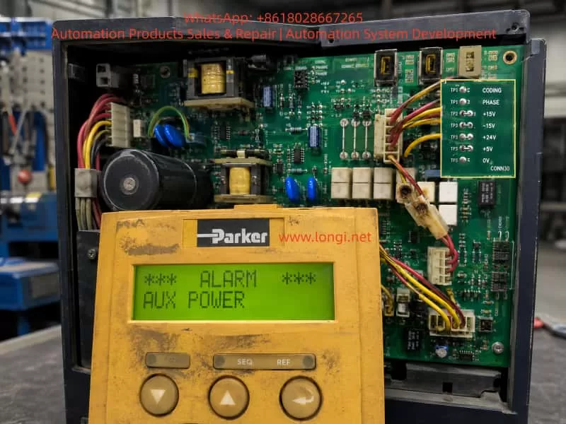
In this case, the observed fault was very typical but also easy to misjudge:

The drive powered up normally. The keypad display was normal. However, once a run/start command was issued, the drive immediately tripped with an AUX POWER alarm.

At first glance, this alarm seems to point directly to an auxiliary power supply problem. A common assumption would be that the internal switching power supply is unstable, or that one of the secondary outputs such as +5 V, +24 V, +15 V, or -15 V collapses when the drive is enabled. The CPU control board was replaced first, but the fault remained unchanged. This proved that the fault was not caused by the CPU board itself. The diagnosis therefore had to move toward the power/drive board, auxiliary supply detection circuit, three-phase mains detection circuit, CODING signal, PHASE signal, and the signals exchanged between the power board and the CPU board.

The important lesson from this case is that AUX POWER on a 590P must not be interpreted only as “the low-voltage switching power supply has failed.” In the Parker 590 series, this alarm can also be triggered by abnormal three-phase mains detection or abnormal coding/synchronization signals.

Parker 590P DC drive showing an AUX POWER alarm on the keypad with the internal power drive board exposed for troubleshooting.

2. Two Different Power Concepts in the 590P

To understand this fault correctly, two power systems inside the drive must be clearly separated.

The first is the single-phase auxiliary supply. The 590P normally has a separate auxiliary supply input, often 110 V or 220 V AC depending on configuration. This auxiliary input powers the internal switching power supply. The switching supply then generates the low-voltage rails used by the electronics, such as:

  • +5 V for logic and CPU-related circuits;
  • +24 V for relays, I/O, fan, and auxiliary control functions;
  • +15 V for analog circuits;
  • -15 V for analog circuits.

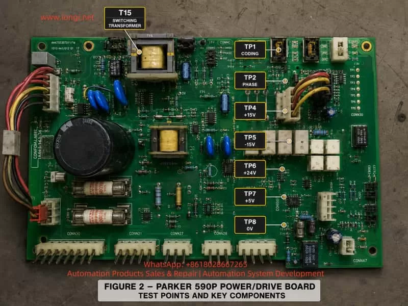
These voltages can be measured on the power board test points:

  • TP7: +5 V
  • TP6: +24 V
  • TP4: +15 V
  • TP5: -15 V
  • TP8: 0 V reference

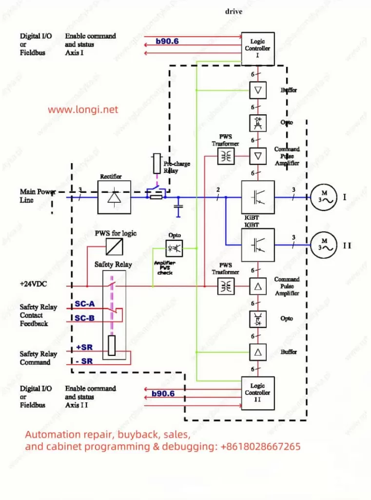
The second is the three-phase mains input, typically L1/L2/L3. This is not only the main power source for the thyristor bridge and DC armature output. It is also used by the control system to generate synchronization information. A DC thyristor drive must know the phase position of the AC supply in order to fire the SCRs at the correct angle. If the phase detection is wrong, missing, unstable, or inconsistent with the expected coding signal, the drive cannot safely run.

Therefore, the three-phase input participates in:

  • phase synchronization;
  • phase-loss detection;
  • phase sequence tracking;
  • mains voltage range recognition;
  • SCR firing reference generation;
  • power-board / stack coding validation.

This is why an AUX POWER fault can still occur even when +5 V, +24 V, +15 V, and -15 V are all present and stable.

Parker 590P power drive board with labeled diagnostic test points including TP1 CODING, TP2 PHASE, +15V, -15V, +24V, +5V, 0V and T15 switching transformer.

3. Why the Low-Voltage Switching Power Supply Was Not the Main Fault in This Case

The initial suspicion was reasonable: if the drive powers up normally but trips immediately after the start command, the auxiliary switching power supply could be weak under load. On older industrial drives, this is common. Aging electrolytic capacitors, a weak UC2844 supply capacitor, poor secondary rectifiers, high ESR output capacitors, or bad solder joints around the switching transformer can all cause a supply to look normal at no load but collapse when the drive is enabled.

The 590P board in this case used a UC2844 PWM controller and a switching transformer, marked T15. Its secondary side generated the low-voltage rails. If T15’s secondary output were weak, one would expect to see one or more of the following:

  • +5 V dipping below about 4.7 V during start;
  • +24 V falling significantly under load;
  • +15 V or -15 V becoming unstable;
  • UC2844 entering undervoltage lockout or hiccup mode;
  • all secondary voltages pulsing or dropping simultaneously;
  • excessive ripple on the electrolytic capacitors near T15.

However, measurements were made at the test points for +15 V, -15 V, +24 V, and +5 V before and after the start command. No obvious voltage change was observed with a multimeter. Although a multimeter may miss very narrow transient dips, the later comparison with a known good power/drive board strongly shifted the diagnosis away from the switching supply itself.

The conclusion was that the basic auxiliary low-voltage supply was probably healthy. The original AUX POWER alarm was more likely caused by the detection and coding section associated with three-phase mains recognition and synchronization.

Technician measuring the TP1 CODING signal on a Parker 590P power drive board, comparing a stable 2.3V good board reading with abnormal faulty board coding voltages.

4. The Real Importance of the CODING Circuit

The 590 series manual describes the coding circuit as being located on the power board. It is not merely a simple fixed resistor identification circuit. It is associated with the generation of synchronization signals for the main processor and the thyristor stack. It also participates in phase-loss detection and automatic phase-sequence tracking.

This is the key point in this case.

The CODING circuit performs several possible functions:

  1. Hardware identification
    The CPU board must know what type of power board, voltage range, stack configuration, and hardware version it is connected to.
  2. Power stack / thyristor synchronization support
    The CPU requires correct timing information before it can fire the SCRs.
  3. Three-phase mains supervision
    If the three-phase input is missing, if one phase is lost, or if the phase detection chain is abnormal, the CPU may receive an invalid coding or phase signal.
  4. Fault classification
    Depending on how the signal fails, the drive may report different alarms, such as SEQ PRE READY, coding-related faults, or AUX POWER.

The 590C documentation also lists two important fault codes:

  • 0xF003: pre-ready fault / coding not present;
  • 0xFF03: auxiliary power fault, with the recommended action to check the auxiliary supply or the three-phase mains input.

This directly matches the field behavior in this case. When the CODING line was manually grounded, the drive displayed SEQ PRE READY, proving that the CPU actively reads this coding signal. But the original fault was AUX POWER, which indicates that the CODING line was not simply absent. Instead, the CPU was likely receiving an abnormal or unstable combination of coding, phase, or mains-status information during the start sequence.

Parker 590P AUX POWER fault diagnostic flow diagram showing three-phase mains input, phase coding detection, LM324 transistor network, TP1 CODING, TP2 PHASE and CPU board signal path.

5. Key Test Result: Good Board vs Faulty Board

The most important diagnostic breakthrough came from comparing the faulty power/drive board with a known good board.
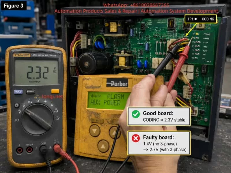
On the good board:

  • Without three-phase 380 V mains applied, TP1 CODING was about 2.3 V DC.
  • With three-phase 380 V mains applied, TP1 CODING remained about 2.3 V DC, with only a slight change.

On the faulty board:

  • Without three-phase mains, TP1 CODING was about 1.4 V DC.
  • With three-phase mains applied but before starting, TP1 CODING rose to about 2.7 V DC.

This comparison is extremely important.

It shows that on a healthy board, TP1 CODING should be a relatively stable identification voltage. It may be related to the coding/synchronization system, but it should not be strongly pulled up or down by the presence of three-phase mains.

On the faulty board, the CODING voltage was already abnormal without three-phase input. It was too low at 1.4 V. When the three-phase supply was applied, it shifted too high to 2.7 V. This means the CODING node was being incorrectly affected by the three-phase detection circuit, PHASE detection circuit, transistor network, op-amp circuit, leakage path, or board contamination.

The fault was therefore not simply “no coding.” If CODING were completely missing, the drive would more likely report a 0xF003 / SEQ PRE READY type fault. Instead, the faulty board produced a wrong or unstable coding condition, which the CPU interpreted as an auxiliary power / mains input abnormality.

6. Why Grounding CODING Caused SEQ PRE READY

During testing, the CODING signal was grounded. The drive then displayed SEQ PRE READY.

This result is logical.

Grounding CODING forces the CPU to see an invalid hardware/coding state. The CPU no longer sees a valid power board identity or coding supply. As a result, it stops at the pre-ready stage and reports a coding-related fault.

This proves several things:

  • CODING is definitely read by the CPU board.
  • CODING is not an ordinary digital alarm line.
  • CODING cannot be grounded, shorted, or bypassed as a repair method.
  • The normal CODING voltage range is meaningful to the CPU.
  • An incorrect CODING level can change the alarm category.

In simple terms:

  • CODING completely invalid or missing → SEQ PRE READY / 0xF003 type fault.
  • CODING present but abnormal in relation to mains/phase detection → AUX POWER / 0xFF03 type fault.

This explains why forcing CODING low did not reproduce the original AUX POWER alarm. It created a different, more fundamental pre-ready fault.

7. The Three Transistors Connected to CODING

Another important observation was that the CODING line was connected to three transistors on the power/drive board. When two of them were removed, the CODING voltage rose to around 4.5 V. When all were removed, the voltage became around 0.5 V.

This proves that these transistors are not unrelated components. They are part of the CODING voltage-generation network.

Such a transistor network may be used for:

  • weighted analog coding;
  • hardware version identification;
  • power stack identification;
  • voltage class coding;
  • phase/mains status gating;
  • fault-state encoding;
  • switching resistor branches into or out of the CODING node.

If one transistor develops leakage, if a base resistor drifts, if a collector-emitter path becomes partially conductive, or if contamination creates a leakage path across the board, the CODING voltage can shift significantly. Because the normal voltage is only around 2.3 V, even a few hundred millivolts of offset may be enough to confuse the CPU.

In this case, the faulty board’s CODING voltage changed from 1.4 V to 2.7 V depending on three-phase mains presence. That is too large to be considered normal. The three-transistor CODING network is therefore one of the first areas to inspect and repair.

The correct repair approach is not to remove transistors and test whether the drive runs. Instead, restore the original circuit and compare each transistor’s base, collector, and emitter voltages against the good board.

8. The Role of LM324 Near the CODING Circuit

The board also has an LM324 near the CODING and PHASE test points. LM324 is a quad operational amplifier commonly used in industrial analog circuits. In this kind of drive board, it may be used for:

  • buffering analog coding voltage;
  • filtering phase detection signals;
  • generating weighted voltage levels;
  • conditioning mains detection signals;
  • summing or comparing several status inputs;
  • driving transistor networks.

If the LM324 has input leakage, output offset, damaged output stage, poor supply, or defective feedback components, it can easily shift the CODING voltage.

The LM324 should be checked carefully by comparing the good board and the faulty board. Important pins include:

  • Pin 4: positive supply;
  • Pin 11: negative supply or ground, depending on circuit design;
  • Pins 1, 7, 8, and 14: op-amp outputs.

The practical method is to measure these pins on both boards under the same conditions:

  1. auxiliary supply only;
  2. auxiliary supply plus three-phase mains;
  3. start command applied;
  4. alarm present.

If one LM324 output on the faulty board changes abnormally with the three-phase mains while the corresponding output on the good board remains stable, that op-amp channel or its surrounding resistor/capacitor network should be investigated.

9. PHASE Signal Must Be Checked Together With CODING

TP2 PHASE should not be ignored. Unlike CODING, which appears as a DC identification voltage, PHASE may be a shaped synchronization signal or a logic signal related to three-phase mains detection. A multimeter may not reveal much about it. An oscilloscope is the correct instrument.

A healthy PHASE signal should be stable when the three-phase mains is present. It should not disappear, jitter heavily, or collapse during the start command.

If TP1 CODING is abnormal and TP2 PHASE is also abnormal, the fault may lie upstream in the three-phase detection chain rather than in the CODING transistor network alone.

The three-phase detection chain may include:

  • L1/L2/L3 mains input;
  • contactor input and output;
  • sampling wires;
  • burnt or oxidized connectors;
  • high-value power resistors;
  • 47 nF Y2 capacitors;
  • optocouplers or isolation modules such as Schurter IF-0321-G;
  • LM393 comparator;
  • LM324 signal conditioning circuit;
  • transistor coding network;
  • TP1 CODING and TP2 PHASE;
  • CPU board input circuits.

Because the drive is a thyristor DC drive, phase synchronization is essential. If the CPU cannot trust the phase signal, it will not allow normal running.

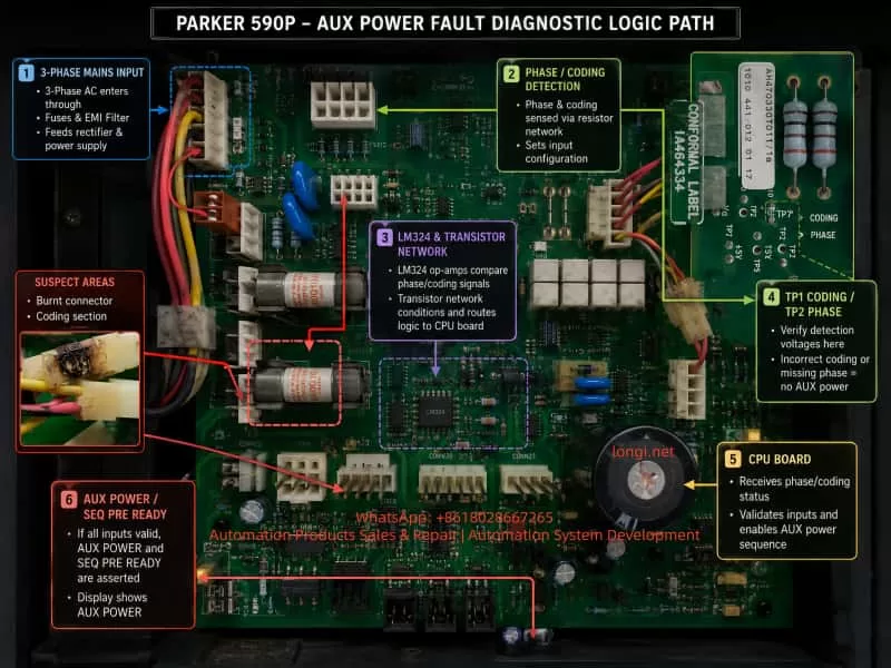
10. The Burnt Connector and Contamination Problem

Several photos showed burnt or darkened connectors and wiring near the three-phase sampling/coding area. This is not a cosmetic issue.

A carbonized connector can cause:

  • high resistance contact;
  • intermittent signal loss;
  • leakage between adjacent pins;
  • unstable three-phase sampling;
  • abnormal analog coding voltage;
  • false phase-loss detection;
  • false AUX POWER alarm.

This is especially serious around high-impedance analog nodes such as CODING. A +24 V relay circuit may tolerate some dirt or contact resistance, but a 2.3 V analog coding node may be disturbed by very small leakage currents.

Any burnt connector in this part of the board should be replaced, not merely cleaned. The PCB surface should be thoroughly cleaned. If the board material is carbonized, the carbonized area should be scraped away and insulated. The terminals and wire crimps should also be replaced or re-crimped if they show heat damage.

11. Why Phase Sequence Alone Is Not the Main Suspect

It is correct that a DC thyristor drive must consider phase sequence and phase synchronization. However, the manual indicates that the coding circuit provides automatic phase-sequence tracking. This means that a simple L1/L2/L3 sequence reversal may not necessarily cause this exact alarm.

More likely causes include:

  • one phase not being detected;
  • one sampling resistor open or drifting;
  • one optocoupler channel weak;
  • one isolation module output abnormal;
  • PHASE signal missing;
  • CODING signal being pulled by the phase detection circuit;
  • contactor output unstable;
  • sampling connector burnt or intermittent;
  • board contamination causing leakage;
  • CPU receiving invalid coding voltage.

Swapping two phases can be used as a diagnostic comparison, but if the fault remains unchanged, the focus should return to phase detection and coding signal conditioning, not merely phase order.

12. Recommended Diagnostic Procedure

For a Parker 590P that powers up normally but trips with AUX POWER when started, the following sequence is recommended.

Step 1: Verify the low-voltage auxiliary rails

Use TP8 as the 0 V reference and measure:

  • TP7 +5 V;
  • TP6 +24 V;
  • TP4 +15 V;
  • TP5 -15 V.

Check these values:

  • with auxiliary supply only;
  • with three-phase mains applied;
  • during start command;
  • after the alarm.

If these voltages remain stable, the low-voltage switching supply is not the main suspect.

Step 2: Measure TP1 CODING

Compare the value with a known good board if possible.

In this case:

  • good board: about 2.3 V with or without three-phase mains;
  • faulty board: 1.4 V without three-phase mains and 2.7 V with three-phase mains.

This confirms an abnormal CODING circuit.

Step 3: Measure TP2 PHASE with an oscilloscope

A multimeter may not be enough. Confirm whether the PHASE signal is present, stable, and consistent when three-phase mains is applied and during the start command.

Step 4: Compare the CODING transistor network

With power off and capacitors discharged, compare the good and faulty boards:

  • TP1 to 0 V resistance;
  • TP1 to +5 V resistance;
  • TP1 to +15 V resistance;
  • TP1 to -15 V resistance;
  • TP1 to TP2 PHASE resistance;
  • TP1 to each transistor pin.

Any major deviation points to leakage or incorrect loading.

Step 5: Replace suspect CODING transistors and inspect resistors

If the CODING voltage is abnormal, the three transistors connected to CODING should be tested or replaced. Their base resistors, collector resistors, emitter resistors, small signal diodes, and filter capacitors should also be inspected.

Step 6: Check LM324 and surrounding components

Compare LM324 output pins on the good and faulty boards. Replace LM324 if one channel output is offset or reacts abnormally to three-phase input.

Step 7: Inspect three-phase sampling and isolation components

Check:

  • high-value sampling resistors;
  • 47 nF Y2 capacitors;
  • Schurter IF-0321-G modules;
  • optocouplers;
  • LM393 comparator;
  • solder joints;
  • burnt plugs;
  • wiring harness.

Step 8: Repair all burnt connectors and contamination

Do not leave carbonized connectors in the circuit. Replace damaged plugs, clean the PCB, repair solder joints, and ensure there is no leakage between signal traces.

13. Final Technical Conclusion

This case shows that the AUX POWER alarm on a Parker 590P DC drive can be misleading if interpreted too narrowly. Although the term suggests an auxiliary power supply fault, the actual detection logic also involves three-phase mains input, coding signal, phase synchronization, and power-board identification.

In this case, the low-voltage auxiliary outputs +5 V, +24 V, +15 V, and -15 V were stable before and after the start command. Therefore, the UC2844 switching power supply and T15 transformer section were not the main fault.

The decisive clue was TP1 CODING. On a good board, TP1 CODING remained approximately 2.3 V whether the three-phase 380 V supply was applied or not. On the faulty board, TP1 was approximately 1.4 V without three-phase supply and 2.7 V with three-phase supply. This proves that the faulty board’s CODING node was being abnormally pulled by the three-phase detection or coding network.

The most probable fault area is therefore:

  • CODING transistor network;
  • LM324 signal conditioning circuit;
  • TP1 surrounding resistors and capacitors;
  • PHASE / three-phase detection coupling path;
  • burnt sampling connectors;
  • isolation components such as IF-0321-G or optocouplers;
  • LM393 phase/mains comparator circuit;
  • PCB contamination or leakage.

The correct repair strategy is to restore the CODING voltage to a stable value close to the good board’s 2.3 V and ensure that TP2 PHASE remains valid during start. Once the CPU receives a valid coding voltage and reliable phase/mains detection signals, the AUX POWER alarm should no longer appear.

The key diagnostic principle is simple:

Do not treat AUX POWER only as a low-voltage power supply fault. On a 590P DC drive, always check the CODING and PHASE detection chain together with the auxiliary power rails.

Posted on

Parker AC10 Series Inverter LU Fault Diagnosis and Troubleshooting Guide: From Theory to Practice

Abstract

In the field of modern industrial automation, Variable Frequency Drives (VFDs) serve as the core equipment for motor control, and their stable operation directly impacts production efficiency and equipment lifespan. The Parker AC10 series inverter is renowned for its simplicity, reliability, and cost-effectiveness, widely used in applications such as fans, pumps, and conveyors. However, the LU fault code (Under-Voltage Protection) is one of the most common issues in this series, often causing equipment downtime. This article begins with the fundamental principles of inverters, provides a detailed analysis of the specifications and internal structure of the Parker AC10 series, and delves into the causes, diagnostic methods, and resolution strategies for LU faults. Through real case studies and preventive maintenance recommendations, it offers comprehensive technical guidance to help engineers solve problems efficiently. The article emphasizes safe operation and parameter optimization in practical application scenarios, aiming to enhance VFD maintenance standards.

LU alarm

Introduction

With the advancement of Industry 4.0, the role of inverters in energy saving, emission reduction, and precision control has become increasingly prominent. According to data from the International Energy Agency (IEA), motor systems consume approximately 46% of the world’s electricity, and inverters can save 20%-30% of this energy. As a global leader in motion and control technology, Parker Hannifin’s AC10 series inverter stands out for its compact design and user-friendly interface. However, in actual operation, faults are inevitable. Among them, the LU fault code is one of the most common protection mechanisms, representing under-voltage protection.

The occurrence of an LU fault usually stems from abnormal input voltage; if not addressed promptly, it can trigger chain reactions such as motor overheating or system collapse. Based on Parker’s official manuals, technical literature, and field experience, this article systematically expounds on the diagnosis and troubleshooting of LU faults. The structure includes inverter fundamentals, an overview of the AC10 series, fault details, cause analysis, diagnostic steps, case studies, preventive measures, and advanced topics. Through a logically rigorous narrative, it ensures readers can fully grasp the relevant knowledge from theory to practice.

Inverter Fundamentals

Definition and Working Principle of Inverters

An inverter is a power electronic device used to control the speed and torque of an AC motor. It achieves flexible drive of the motor by changing the output voltage and frequency. The basic structure includes a rectifier unit, a filter unit, an inverter unit, and a control unit.

  • Rectifier Unit: Converts input AC power into DC power, typically using a diode bridge rectifier. For a three-phase input, the output DC voltage (DC Bus) is approximately 1.414 times the input line voltage. For example, with a 380V input, the DC Bus is approximately 537V.
  • Filter Unit: Uses large-capacity electrolytic capacitors to smooth the DC voltage and reduce ripple. Under-voltage faults are often related to this unit; if the capacitor ages or the input voltage is insufficient, the DC Bus voltage will drop below the threshold.
  • Inverter Unit: Uses power devices such as IGBTs or MOSFETs to invert the DC power into adjustable frequency AC power for output to the motor.
  • Control Unit: Based on a microprocessor, it implements algorithms such as vector control and V/F control. The Parker AC10 supports sensorless vector control, providing precise torque response.

The protection functions of an inverter are crucial, including Over-Current (OC), Over-Voltage (OE), Overload (OL), and Under-Voltage (LU). LU protection is a safety mechanism that triggers when the DC Bus voltage falls below a set threshold to prevent equipment damage caused by operation under low voltage.

Application of Inverters in Industry

In the manufacturing industry, inverters are widely used for constant pressure water supply, fan speed regulation, and conveyor belt control. For example, in the textile industry, the AC10 can precisely control the speed of a spinning machine to reduce yarn breakage. Under-voltage faults occur frequently in areas with unstable power grids, such as remote factories or during peak electricity usage periods, leading to production interruptions. Understanding the basic principles helps in quickly locating the problem.

Overview of the Parker AC10 Series

Product Specifications and Features

The Parker AC10 series is an economical compact inverter with a power range from 0.2kW to 180kW (IP20 protection level) or 0.4kW to 90kW (IP66). It supports single-phase 230V, three-phase 230V, or 380-480V input voltage, with an output frequency of 0-400Hz. Key specifications include:

ParameterSpecification Description
Input Voltage3-phase 380-480V (+10%/-15%)
Output Power0.2-180kW
Overload Capacity150% for 1 minute, 180% for 2 seconds
Control ModeV/F, Sensorless Vector
Protection FunctionIP20/IP66, Built-in EMC Filter
InterfaceRS485 Modbus, Keypad Display

The AC10 adopts a modular design, with internal circuits including a power board, a control board, and a drive board. The power board is responsible for rectification and filtering, while the control board processes signals and parameters. Features include a built-in PID controller, auto-tuning, and display of up to 15 fault codes.

Internal Circuit Structure

The internal circuit of the AC10 focuses on efficiency and reliability. The input passes through an EMI filter to a rectifier bridge (typically 6 diodes) to generate the DC Bus. Electrolytic capacitors (typically rated for 450V) store energy, and an IGBT module inverts the output. A voltage sampling circuit monitors the DC Bus in real-time; if it falls below the threshold (approximately 320-340V for 380V models), it triggers an LU fault.

A control chip (such as the STM32 series) processes the fault logic. Common components on the power board include relays (HF105F), transformers, and resistor voltage divider networks. Loose connections often occur between these components, causing intermittent under-voltage.

AC10G-410-3200

Detailed Explanation of LU Fault Code

Meaning of the LU Code

In the Parker AC10 series, LU stands for “Low Voltage” or “Under Voltage,” i.e., under-voltage protection. When the inverter detects that the input voltage or DC Bus voltage is below the safety threshold, it displays LU and stops output. This is an active protection mechanism to avoid IGBT damage or motor loss of control when operating under low voltage.

According to the manual, the LU trigger threshold is usually 85%-90% of the input voltage. For example, in a 380V system, the threshold is approximately 320V. The fault code is displayed on the LED panel, accompanied by a buzzer or flashing indicator light.

Distinction from Other Faults

LU is different from Over-Voltage (OE) or Phase Loss (PF1). OE is caused by a high DC Bus, often due to regenerative energy; PF1 is caused by a missing input phase, leading to imbalance. LU focuses specifically on low voltage and is usually not accompanied by current abnormalities.

Common Cause Analysis

The causes of LU faults are diverse and can be divided into external and internal factors. Based on industry experience and literature, the following are common causes ranked by probability:

  1. Input Power Supply Voltage Too Low (Most Common, ~60%)
    Grid fluctuations, peak loads, or long-distance transmission cause voltage drops. Both steady-state under-voltage (e.g., below 380V) and instantaneous sags can trigger it. The International Electrotechnical Commission (IEC) standard defines a voltage sag as a voltage drop below 90% lasting 10ms to 1 minute.
  2. Power Connection Issues (~25%)
    Loose terminals, oxidized cables, or poor contact cause intermittent voltage drops. In user cases, loose wires on the power board fall into this category. Loose connections increase impedance, leading to a reduction in effective voltage.
  3. Input Phase Loss or Imbalance (~10%)
    A broken wire in one phase or a blown fuse causes unstable rectifier output. The AC10 may report LU first and then switch to PF1.
  4. Internal Component Failure (~5%)
    Aging of electrolytic capacitors (capacity attenuates by 20% after 5 years of use), damage to the rectifier bridge, or offset in the voltage sampling circuit. High-temperature environments accelerate aging.
  5. Incorrect Parameter Settings
    The under-voltage threshold (P07.XX parameter) is set too high, or the input voltage range is set incorrectly.

Other rare causes include electromagnetic interference or load-side feedback, but the probability is low.

Diagnosis and Troubleshooting Steps

Diagnosing an LU fault requires a systematic approach, ensuring safety (de-energized operation). The following is a step-by-step guide:

Step 1: Initial Inspection and Reset

  • Observe the Panel: Confirm the LU code and record accompanying symptoms (e.g., motor not turning).
  • Reset: Press the STOP/RESET key. If it reappears immediately, the problem is persistent; if it recovers, it may have been a transient sag.

Step 2: Measure Input Voltage

  • Use a digital multimeter (e.g., Fluke) to measure the three-phase line voltages (L1-L2, L2-L3, L3-L1). Normal values should be within 380-480V ±10%.
  • If low: Check the power grid, transformer, or upstream switches. Add a voltage stabilizer or compensation capacitor.
  • Measure DC Bus: After power-off and discharging, connect probes to the P+ and N- terminals. Normal value is around 565V (as per user photos).

Step 3: Check Connections and Wiring

  • Inspect input terminals, cables, and contactors. Tighten screws and clean oxidation.
  • Test Continuity: Use the ohmmeter range to check inter-phase impedance; there should be no open circuit.

Step 4: Internal Inspection

  • Open the unit and inspect the power board: check for capacitor bulging, burn marks, or loose wires (as in the user case).
  • If capacitor is faulty: Replace with the same specification (e.g., 330μF 450V).

Step 5: Parameter Verification

  • Enter the menu (press M key): Check P07.02 (DC Bus voltage) and P00.11 (input voltage setting). Restore factory defaults if necessary.

Step 6: Test Run

  • Connect to a backup power source for testing. If normal, confirm an external issue; otherwise, send for repair.

Throughout the process, wear insulated gloves and avoid live operations.

Case Studies

Analysis of a Real Fault Case

In a factory’s conveying system using a Parker AC10 5.5kW model (Model 10G-43-0120-BF), an LU fault suddenly appeared. Initial inspection showed the input voltage was normal (approx. 400V), but the DC Bus was only 565V (below normal).

Upon further disassembly, a wire connecting the rectifier bridge on the power board was found to be loose (see user photo). The looseness increased contact resistance, causing an instantaneous voltage drop that triggered the LU. After re-plugging and securing the wire, the equipment returned to normal.

Analysis: Vibration environments cause wires to loosen, which is a connection issue. Prevention: Secure with cable ties.

This case highlights the importance of measurement and visual inspection, saving the cost of replacing components.

Simulated Case: Grid Fluctuation

Assume a water pump application where a grid sag causes an LU fault. Solution: Install a UPS or Dynamic Voltage Restorer (DVR), costing approximately $2000, but avoiding downtime losses.

Prevention and Maintenance Strategies

Prevention is better than cure. The following is a maintenance guide for the AC10:

Regular Maintenance Schedule

  • Monthly: Clean dust and check terminal tightness.
  • Quarterly: Measure voltage and test capacitor capacity (using an LCR meter).
  • Yearly: Comprehensive overhaul and software upgrade.

Environmental Optimization

  • Install in a ventilated cabinet to avoid high temperatures (>40°C).
  • Use EMC filters to reduce interference.

Parameter Optimization

  • Set P00.13 to auto-restart to reduce manual intervention.
  • Monitor Logs: The AC10 supports fault history recording (P14.XX).

Implementing these measures can reduce the fault rate by 30%.

Advanced Topics: Parameter Adjustment and Circuit Analysis

Parameter Deep Dive

The AC10 parameter groups include P00 (Basic), P01 (Motor), and P07 (Monitoring). Under-voltage related parameters: P07.01 (Input Voltage), P11.08 (Under-voltage Threshold). Adjusting the threshold requires caution to avoid false protection.

In-depth Internal Circuit Analysis

Power Board Circuit: The input passes through a fuse to the rectifier bridge. Behind the bridge, capacitors and discharge resistors are connected in parallel. Sampling is performed via a voltage divider resistor to the ADC. When a fault occurs, the MCU compares the value and triggers an interrupt.

For maintenance, it is recommended to use an oscilloscope to observe ripple (normal <5%). If an IGBT fails, it may cause a chain reaction LU fault.

IoT Integration Monitoring

Modern Trend: Connect RS485 to a SCADA system for real-time voltage monitoring. Parker provides software tools such as Drive System Explorer.

Conclusion

While the LU fault in the Parker AC10 series is common, it can be efficiently resolved through systematic diagnosis. This article covers the full spectrum of knowledge from basics to advanced topics. The key takeaway is: Safety First, Prevention Oriented. In the future, with the development of intelligent diagnostic technologies, VFD faults will become easier to predict. I hope this article helps you master the techniques and improve efficiency.

Posted on

Engineering Analysis and Systematic Repair Strategy for “All LEDs Flashing + ISSUE” Condition on Parker 590 Digital DC Drives

Abstract

The Parker 590 Digital DC Drive is a widely used high-performance DC speed controller applied in rolling mills, extrusion lines, wire drawing machines, paper production, printing equipment, and chemical process systems.
A frequently misunderstood fault condition encountered in field service is the following: immediately after power-up, all LEDs on the keypad flash simultaneously, and the display shows “DIGITAL DC DRIVE – ISSUE x.x”. The drive does not enter normal operation or parameter menus.

This condition is often incorrectly treated as a parameter problem, accidental calibration mode, or software issue. In reality, it almost always indicates an internal startup failure of the control system.

This paper provides a system-level engineering explanation of this phenomenon, analyzes its root causes, and proposes a structured troubleshooting and repair methodology suitable for industrial maintenance professionals.


DIGITAL DC DRIVE   ISSUE:7.4

1. System Architecture and Startup Logic of the Parker 590

To correctly understand the “ISSUE + all LEDs flashing” condition, it is essential to first review the internal architecture of the Parker 590.

From a system perspective, a Parker 590 DC drive consists of the following major functional blocks:

  1. Control Power Supply (SMPS)
    Generates regulated low-voltage rails such as +5 V, ±15 V, and +24 V for logic and analog circuits.
  2. Main Control System (MCU/DSP/CPLD)
    Executes firmware responsible for self-tests, parameter management, communications, control algorithms, and protection logic.
  3. Human-Machine Interface (HMI)
    Keypad, LEDs, and LCD module communicating with the main controller.
  4. Power and Firing System
    Gate drive circuits, armature and field control, SCR or transistor trigger boards.
  5. Measurement and Protection Circuits
    Voltage/current sensing, isolation, hardware protection channels.

The normal startup sequence of the Parker 590 is:

  • Control power supply starts
  • Logic voltages stabilize
  • Reset is released
  • Clock oscillation established
  • Boot code executed
  • Internal hardware self-test
  • Parameter memory verification
  • Power section status check
  • Transition to READY/STOP state

If any critical stage fails, the drive will not enter normal operating mode.


2. Engineering Meaning of “All LEDs Flashing + ISSUE”

In Parker 590 terminology, “ISSUE” is not a user fault code (such as overcurrent or overvoltage). It is an internal startup diagnostic indication.

It means:

The drive failed to complete its initialization and self-test sequence and did not reach a valid operational state.

Typical characteristics of this condition include:

  • All keypad LEDs flashing synchronously
  • Display fixed on “ISSUE x.x”
  • Inability to enter standard menus
  • Weak or absent keypad response
  • State remaining unchanged or repeatedly resetting

This is fundamentally a boot or initialization failure, not an application or parameter fault.

At this stage, the controller is not fully running and cannot reliably execute parameter handling, calibration routines, or normal control logic.


DIGITAL DC DRIVE DC 2Q 35A

3. Distinction from Calibration or Engineering Modes

Parker 590 drives do have special engineering or calibration modes that may involve unusual LED behavior. These are sometimes confused with the ISSUE condition.

However, there are decisive differences.

3.1 Characteristics of Calibration / Engineering Modes

  • Clear menu or calibration item displayed
  • Keys respond normally
  • Structured menu navigation
  • No “ISSUE” indication
  • System already fully operational

These modes require the CPU, memory, and power rails to be fully functional.

3.2 Characteristics of Startup Failure Mode

  • Appears immediately at power-up
  • Not triggered intentionally
  • Display shows “ISSUE”
  • No access to normal menus
  • All LEDs flash together
  • Indicates incomplete system initialization

A fundamental maintenance rule for Parker 590 drives is therefore:

If menus are accessible, investigate parameters or calibration.
If menus are inaccessible and ISSUE is displayed, treat it as a hardware startup failure.


4. Root Cause Classification

Based on extensive industrial repair experience, the “ISSUE + all LEDs flashing” condition almost always originates from the internal control system. Root causes fall into three primary categories.


4.1 Control Power Supply Failure (Highest Probability)

This is the most frequent cause.

Typical problems include:

  • Switching power supply not starting
  • One voltage rail missing or undervoltage
  • Excessive ripple or oscillation
  • Power supply unable to sustain load
  • Cyclic startup and collapse (hiccup mode)

Common failed components:

  • PWM controller ICs
  • Startup resistors
  • Secondary rectifier diodes
  • Optocouplers and reference circuits
  • Small electrolytic capacitors

Any instability in the logic supply will continuously reset the CPU, preventing successful initialization.


4.2 Main Control Board or Processor Failure

Examples include:

  • Damaged MCU or DSP
  • Corrupted or inaccessible program memory
  • Clock oscillator failure
  • CPLD/FPGA malfunction
  • Reset or enable circuit faults

Typical causes:

  • Lightning or surge events
  • 24 V misapplied to logic terminals
  • External high-voltage intrusion
  • Severe power disturbances
  • Long-term thermal degradation

In such cases, logic voltages may appear normal, but the controller never executes firmware correctly.


4.3 Internal Load or Subsystem Short Circuit

For example:

  • Shorted gate-drive board
  • Faulty interface or communication modules
  • Analog input/output circuit failure

This category is characterized by:

  • Power supply stable when unloaded
  • Voltage collapses when specific boards are connected
  • Reproducible failure when certain modules are installed

Isolation and staged reconnection are required to identify the defective subsystem.


5. Systematic Engineering Troubleshooting Procedure

A structured troubleshooting process is essential to avoid misdiagnosis.


Step 1 – External Isolation

Disconnect:

  • Armature circuit
  • Field circuit
  • Encoder
  • I/O wiring
  • Communication cables
  • External 24 V sources

Leave only the control power supply.

This excludes external shorts and miswiring.


Step 2 – Comprehensive Power Rail Measurement

Measure and verify:

  • +5 V (critical digital rail)
  • +15 V / –15 V (analog rails)
  • +24 V (if applicable)

Check for:

  • Presence
  • Correct level
  • Stability
  • Ripple and transient behavior

Any abnormality must be corrected before further investigation.


Step 3 – Oscilloscope Verification of Core Signals

Key points include:

  • MCU clock output
  • Reset line behavior
  • 5 V ripple and noise
  • Power-supply feedback signals

Typical faults observed:

  • No clock oscillation
  • Reset permanently asserted
  • Periodic voltage collapse

These directly confirm startup failure mechanisms.


Step 4 – Load Isolation Method

If power instability is suspected:

  • Disconnect control boards
  • Disconnect firing or interface boards
  • Reconnect subsystems sequentially

This identifies which unit overloads the power supply.


Step 5 – Logic Startup Chain Validation

After confirming stable voltages:

  • Verify reset release
  • Confirm clock stability
  • Check memory communication
  • Inspect bus lines for shorts

This differentiates power-supply faults from processor-level failures.


6. Why Recalibration Cannot Solve This Condition

Calibration routines require:

  • A running CPU
  • Accessible parameter memory
  • Stable logic power
  • Functional communication between subsystems

The ISSUE condition explicitly indicates these prerequisites are not satisfied.
Therefore, recalibration is not a valid corrective action.

This fault occurs before the system reaches any state capable of executing calibration or configuration code.


7. Engineering Conclusion and Maintenance Strategy

When a Parker 590 drive exhibits:

  • All LEDs flashing immediately at power-up
  • Display showing “ISSUE”
  • No access to standard menus

It should be formally classified as:

Control system startup failure (boot failure / logic supply fault)

Correct maintenance strategy focuses on:

  • Control power supply integrity
  • Main controller startup chain
  • Internal load and subsystem isolation

Not on parameters, tuning, or external control signals.


8. Final Remarks

The Parker 590 is a robust and highly repairable industrial drive.
The “ISSUE + all LEDs flashing” symptom is not random or obscure; it is a consistent indicator of startup-level failure.

By approaching the problem from a system engineering perspective—centered on power integrity, processor initialization, and internal loading—most drives exhibiting this condition can be diagnosed efficiently and restored successfully.

Posted on

Analysis and Troubleshooting of Parker TWIN-N Servo Drive Error Code Er.25

Introduction

In modern industrial automation, servo drives play a crucial role. Acting as the bridge between motors and control systems, they must not only provide stable power and driving capability but also precisely process real-time signals from feedback devices. If the feedback system fails, the drive cannot initialize or operate correctly, leading to fault alarms and machine downtime.
This article focuses on Error Code Er.25 in Parker TWIN-N series servo drives, analyzing its definition, root causes, troubleshooting methods, and preventive measures. It also presents real case studies and maintenance guidelines, offering engineers and technicians a comprehensive reference to handle this error effectively.


TWIN8NSE

1. Overview of Parker TWIN-N Series Servo Drives

Parker Hannifin is a globally recognized provider of motion and control technologies. Its TWIN-N series servo drives are widely applied in packaging machines, textile equipment, electronic manufacturing, and other high-precision industrial automation fields.

Key features of the TWIN-N series include:

  1. Dual-axis design: One drive can simultaneously control two brushless motors, saving space and cost.
  2. Multiple feedback compatibility: Supports Resolver, Incremental Encoder, SinCos, EnDat, and Hiperface.
  3. Flexible parameter configuration: Different motor and feedback types can be adapted via parameter settings.
  4. Advanced control functions: Provides position control, speed control, torque control, electronic cam, and other functions.

Among these functions, the correct initialization of feedback signals is critical. When the drive cannot establish a valid speed loop feedback, it triggers the Er.25 alarm.


2. Official Definition of Er.25

According to the Parker TWIN-N / SPD-N user manual:

Er.25 – Speed loop FBK initialization error

Recommended actions:

  • Check speed feedback (Speed FBK) parameter settings.
  • Check speed feedback (Speed FBK) connections.

This indicates that during startup, the drive fails to initialize the feedback required for the speed loop. Essentially, the drive cannot obtain valid speed feedback from the encoder or resolver, preventing the closed-loop control system from functioning.


3. Possible Causes of Er.25

Based on the manual and practical field experience, the following are the most likely causes of Er.25:

3.1 Incorrect feedback type configuration

The drive supports different feedback devices, and each requires correct parameter configuration:

  • Resolver mode for resolver feedback.
  • Incremental encoder mode with proper pulse number and supply voltage.
  • EnDat or Hiperface modes with specific communication protocols.

If the configuration does not match the actual feedback hardware, the initialization fails.

3.2 Wiring and connection issues

Feedback wiring typically includes power supply, signal lines, and shielding. Problems such as:

  • No voltage or reversed polarity on +5V / +8V power.
  • Broken, shorted, or swapped A/B/Z channels.
  • Incorrect Sin+/Sin− / Cos+/Cos− wiring.
  • Improper grounding of shield cables.

These can all cause the initialization error.

3.3 Faulty feedback device

Internal damage to the feedback device may lead to errors:

  • Open winding in resolver.
  • Malfunctioning photodiode in optical encoders.
  • EEPROM failure in EnDat/Hiperface devices.

3.4 Electromagnetic interference (EMI) and environment

Industrial sites often have strong EMI sources such as welding machines, large inverters, or solenoids. Poor shielding or excessive cable length may cause unstable signals at startup, leading to Er.25.

3.5 Drive hardware or firmware issues

If the feedback input board is defective or the firmware has bugs, the drive may also fail to initialize. Though less common, this should be considered after external causes are ruled out.


er.25

4. Step-by-Step Troubleshooting

A structured troubleshooting process ensures efficient diagnosis and resolution:

Step 1 – Verify feedback type configuration

  • Check drive parameter (e.g., Pr196) to confirm correct selection of Resolver, Incremental, or SinCos feedback.
  • Compare motor nameplate and encoder type with drive configuration.

Step 2 – Verify feedback power supply

  • Measure encoder supply voltage (+5V or +8V) with a multimeter.
  • Confirm stable supply, correct polarity, and no short circuits.

Step 3 – Inspect wiring and signals

  • Use an oscilloscope to check A/B/Z or Sin/Cos waveforms.
  • Ensure signal symmetry, integrity, and no significant noise.
  • Confirm secure wiring and proper shield grounding.

Step 4 – Perform encoder phasing (alignment)

  • Execute encoder phasing procedure if using incremental or SinCos encoders.
  • For EnDat/Hiperface, re-download EEPROM data if required.

Step 5 – Cross-test with a spare feedback device

  • Replace with a known good encoder/resolver to rule out sensor damage.

Step 6 – Check drive hardware

  • If external checks are normal, suspect damage to feedback interface or firmware issues. Contact the manufacturer or service center for repair.

5. Case Study

In a production line, a Parker TWIN8NSE K006 drive repeatedly showed Er.25 during startup. Investigation revealed:

  • The motor used an incremental encoder, but the drive remained configured in Resolver mode.
  • The encoder supply voltage was correct, but no pulses were detected at the signal terminals.

Solution:

  1. Corrected the feedback type parameter to “Incremental Encoder.”
  2. Re-wired the feedback cable and performed encoder phasing.
  3. Restarted the drive, and the error disappeared.

This case highlights the importance of both parameter configuration and wiring inspection.


6. Preventive Measures

To minimize recurrence of Er.25, the following preventive practices are recommended:

6.1 Proper cabling

  • Use twisted, shielded cables for feedback signals.
  • Avoid routing feedback lines parallel to power cables.
  • Keep cable length within the specified range (typically 20–35 m).

6.2 Routine inspection

  • Check encoder waveforms every six months.
  • Clean connectors regularly to prevent dust or oil contamination.

6.3 Parameter management

  • After replacing or resetting the drive, always reconfigure feedback parameters.
  • Ensure firmware version supports the chosen feedback protocol.

6.4 Parameter backup

  • Save drive parameters in normal operation for quick restoration after faults.

6.5 EMI control

  • Keep drives away from strong EMI sources.
  • Use isolation transformers or EMI filters when necessary.

7. Conclusion

Error Code Er.25 in Parker TWIN-N series servo drives is a speed loop feedback initialization error. It is most commonly caused by incorrect feedback configuration, wiring problems, or faulty encoders. By applying a systematic troubleshooting approach—checking parameters, verifying wiring, confirming power, and testing feedback devices—engineers can quickly resolve the issue.

From a broader perspective, the feedback system acts as the “sensory organ” of the servo drive. Any malfunction, however minor, can disrupt the entire closed-loop system. Understanding the logic behind fault codes, combined with preventive maintenance practices, is essential for ensuring the long-term stability and reliability of servo drive systems.


Posted on

Application Scheme of Parker 590+ DC Drive in Blow Molding Machines

I. Introduction

Blow molding machines are critical equipment for producing hollow plastic products (such as PE bottles and containers). The process involves several steps, including extrusion, clamping, blow molding, cooling, and mold opening. The Parker 590+ DC drive, with its precise speed and torque control capabilities, is particularly well-suited for controlling DC motors in blow molding machines. This document elaborates on how to apply the 590+ drive to a PE material blow molding machine, covering motor functions, wiring schemes, parameter settings, control system integration, and textual descriptions of electrical wiring diagrams and control schematics.

II. Analysis of Motor Functions in Blow Molding Machines

The process flow of a blow molding machine (especially for PE material extrusion blow molding) includes:

  • Extrusion: Plastic pellets are melted through the extruder screw to form a tubular parison.
  • Clamping: The mold closes, clamping the parison.
  • Blow Molding: Air is injected into the parison to expand and form the shape.
  • Cooling: The molded product is cooled.
  • Mold Opening: The mold opens, and the finished product is removed.

Motor Functions
Based on the blow molding process, the following motors are suitable for use with the 590+ DC drive:

  • Extruder Motor:
    • Function: Drives the screw to control plastic melting and extrusion speed.
    • Requirements: Precise speed control, smooth acceleration/deceleration, and overload protection.
    • Reason: PE materials require a stable extrusion speed to ensure uniform parison formation. Baumüller emphasizes the need for high torque and precise speed control in extruders.
  • Clamping Unit Motor:
    • Function: Controls the opening and closing of the mold.
    • Requirements: Rapid response and precise speed or position control.
    • Reason: Quick and accurate mold movements can improve production efficiency. Plastics Technology mentions the need for precise control in clamping systems.

Motor Specifications (Based on User Input)

  • Rated Voltage: 440V
  • Rated Current: 25.1A
  • Power: 15kW
  • Speed: 1500 rpm
  • Field Excitation: Field current not provided; assumed to use voltage control mode.
  • Assumption: The extruder motor uses the above specifications. The clamping unit motor specifications may differ (e.g., 10A, assumed value) and should be adjusted according to the actual nameplate.

III. Application Design of the 590+ DC Drive

  1. Application Positions and Functions
    • Extruder Motor
      • Control Mode: Speed Setpoint mode.
      • Function: Precisely control the screw speed to ensure uniform melting of PE materials; maintain stable extrusion through PID control; use Ramp function for smooth start-up and shutdown.
      • Implementation: The drive receives a 0-10V speed reference signal from the PLC and feeds back the actual speed through an encoder or DC generator.
    • Clamping Unit Motor
      • Control Mode: Speed Setpoint mode (or Position Control mode if supported).
      • Function: Control the rapid closing and opening of the mold; ensure precise movements and reduce mechanical shock.
      • Implementation: The drive receives open/close commands from the PLC and may use limit switches for position control.
  2. Wiring Scheme
    • Motor Connections
      • Extruder Motor: Connect the armature to the drive’s A1 (positive)/A2 (negative) terminals; if the field is internally powered, no connection is needed; if external, connect to FL1/FL2 terminals (refer to Eurotherm Manual).
      • Clamping Unit Motor: Same as above, to be confirmed based on actual motor specifications.
    • Control Signal Connections
      • Speed Reference: Connect the PLC analog output (0-10V) to the A4 terminal (ANIN3), ensuring signal shielding to reduce noise.
      • Start/Stop: Connect the PLC digital output to the C3 terminal (DIGN2 for start); connect the PLC digital output to the C4 terminal (DIGN3 for stop, or use a single signal).
      • Feedback: Connect the encoder to the drive’s encoder input terminals; connect the DC generator to the TB terminal.
      • Communication: Connect the P3 port to the PLC communication interface (e.g., RS-485) for data exchange.
    • Power Connections
      • Main Power: Connect the three-phase AC power (380V or matching voltage) to the L1/L2/L3 terminals.
      • Control Power: Connect 24V DC to the C9 (+24V)/C10 (0V) terminals.
    • Wiring Precautions
      • Use shielded cables to reduce electromagnetic interference.
      • Ensure proper grounding to comply with safety standards.
      • Refer to the wiring diagram in Appendix L of the manual.
  3. Parameter Settings
    • Extruder MotorParameter NameLabelSetting ValueRangeDefault ValueNotesARMATURE V CAL.201.03530.9800 to 1.10001.0000Voltage switch set to 425VCUR. LIMIT/SCALER15100.00%0.00 to 200.00%100.00%Corresponding to 25.1AMAIN CURR. LIMIT421100.00%0.00 to 200.00%200.00%Adjustable as neededFIELD CONTROL MODE209VOLTAGEVOLTAGE/CURRENTVOLTAGEVoltage control modeRATIO OUT/IN21090.00%0.00 to 100.00%90.00%Initial field voltage ratioSPEED FBK SELECT10ENCODERMultiple options-Assume using encoderMODE1Speed SetpointMultiple modes-Speed control modeRAMP RATE (Accel)25.0 seconds0.1 to 600.0 seconds-Smooth accelerationRAMP RATE (Decel)35.0 seconds0.1 to 600.0 seconds-Smooth deceleration
    • Clamping Unit Motor
      • Assume current is 10A; other parameters are similar.
    • Setting Steps
      • Enter the configuration mode via MMI (CONFIGURE ENABLE = ENABLED).
      • Set the above parameters, referring to the manual’s menu system.
      • Save the parameters (CONFIGURE ENABLE = DISABLED).
  4. Control System Integration
    • PLC Selection
      • Recommended: Siemens S7-1200 (compact, suitable for small and medium-sized blow molding machines) or S7-300 (suitable for large equipment).
      • Functions: Control the process flow (extrusion, clamping, blow molding, mold opening); send analog signals (speed reference) and digital signals (start/stop); receive feedback from the drive (speed, current, faults).
      • Modules: Analog output module (e.g., EM 231, 0-10V); digital output module (e.g., EM 222); communication module (e.g., RS-485).
    • HMI Selection
      • Recommended: Siemens KTP700 Basic or Allen-Bradley PanelView Plus.
      • Functions: Display extrusion speed, motor current, fault status; provide start/stop buttons, speed setting interface; alarm management.
      • Interface Example: The home page displays running status, speed, and current; the setting page adjusts extrusion speed and clamping speed; the alarm page displays drive fault codes.
    • Industrial PC (Optional)
      • Recommended: Siemens Simatic IPC477E or Beckhoff CX5130.
      • Functions: Recipe management (store parameters for different PE products); data logging (production data, fault logs).
      • Applicable Scenarios: Large production lines or when advanced automation functions are required.
    • Control Logic
      • PLC Program: The main cycle executes the process steps in sequence (extrusion → clamping → blow molding → cooling → mold opening); set the speed reference (e.g., 50%) when the extruder starts and activate the C3 terminal; stop by closing the C3 terminal and setting the speed to 0; send a close command (speed 100%) to the clamping unit before blow molding and an open command (speed -100% or reverse) after blow molding.
      • Example Logic (Textual Description)
        • Press the “Start” button: Output the speed reference (Q0.0, 0-10V) to A4; activate C3 (Q0.1, start).
        • Clamping phase: Output the clamping speed (Q0.2, 0-10V) to the clamping drive’s A4; activate the clamping C3 (Q0.3, start).
  5. Electrical Wiring Diagram and Control Schematic
    • Extruder Wiring Diagram (Textual Description)
      • [Three-phase power 380V] –> [L1/L2/L3] –> [590+ input terminals]
      • [24V DC power] –> [C9(+24V)/C10(0V)] –> [590+ control power]
      • [Extruder motor armature] –> [A1/A2] –> [590+ output terminals]
      • [Extruder motor field] –> [FL1/FL2] –> [590+ field terminals] (if external)
      • [PLC analog output 0-10V] –> [A4(ANIN3)] –> [590+ speed reference]
      • [PLC digital output] –> [C3(DIGN2)] –> [590+ start]
      • [PLC digital output] –> [C4(DIGN3)] –> [590+ stop]
      • [Encoder] –> [Encoder input] –> [590+ feedback]
    • Clamping Unit Wiring Diagram (Textual Description)
      • [Three-phase power 380V] –> [L1/L2/L3] –> [590+ input terminals]
      • [24V DC power] –> [C9(+24V)/C10(0V)] –> [590+ control power]
      • [Clamping motor armature] –> [A1/A2] –> [590+ output terminals]
      • [Clamping motor field] –> [FL1/FL2] –> [590+ field terminals] (if external)
      • [PLC analog output 0-10V] –> [A4(ANIN3)] –> [590+ speed reference]
      • [PLC digital output] –> [C3(DIGN2)] –> [590+ start]
      • [PLC digital output] –> [C4(DIGN3)] –> [590+ stop]
      • [Limit switch] –> [Digital input] –> [590+ position feedback]
    • Control Schematic (Textual Description)
      • [Operator] –> [HMI KTP700]
      • [HMI] –> [PLC S7-1200]
      • [PLC] –> [Analog output Q0.0] –> [Extruder 590+ A4]
      • [PLC] –> [Digital output Q0.1] –> [Extruder 590+ C3]
      • [PLC] –> [Analog output Q0.2] –> [Clamping 590+ A4]
      • [PLC] –> [Digital output Q0.3] –> [Clamping 590+ C3]
      • [Extruder 590+] –> [Extruder motor] –> [Screw]
      • [Clamping 590+] –> [Clamping motor] –> [Mold]
      • [PLC] –> [Other control] –> [Blow molding valve, cooling system]

IV. Implementation Steps

  1. Wiring
    • Confirm the power supply voltage (380V or matching).
    • Connect the motor armature (A1/A2) and field (FL1/FL2, if needed).
    • Connect the control power (C9/C10).
    • Connect the PLC analog output to A4 and digital output to C3/C4.
    • Connect the feedback device (encoder or DC generator).
    • Connect the P3 port to the PLC communication interface.
  2. Parameter Setting
    • Enter the MMI and set CONFIGURE ENABLE = ENABLED.
    • Set parameters such as armature voltage, current limit, field control mode, etc.
    • Configure speed feedback and control mode.
    • Save the parameters and set CONFIGURE ENABLE = DISABLED.
  3. PLC and HMI Configuration
    • Write the process control program in the PLC.
    • Configure the HMI interface, adding status displays and control buttons.
    • Test the communication (PLC with the drive).
  4. Testing and Debugging
    • Power on and check the drive status (no alarms).
    • Start the extruder via the HMI and verify speed control.
    • Test the clamping unit’s opening and closing to ensure accurate movements.
    • Adjust parameters (e.g., Ramp time, PID gain) to optimize performance.

V. Precautions

  • Safety: Ensure power is disconnected before wiring and follow electrical safety standards.
  • Debugging: Test gradually to avoid motor overload or mechanical damage.
  • PE Material Characteristics: Ensure that the extrusion speed is coordinated with temperature control (refer to ScienceDirect).
  • Manual Reference: Detailed wiring and parameter settings should be consulted in the Eurotherm Manual.

VI. Conclusion

By applying the Parker 590+ DC drive to the extruder and clamping unit of a blow molding machine, precise motor control can be achieved, improving the production efficiency and quality of PE products. The wiring scheme ensures reliable signal transmission, parameter settings match motor requirements, and PLC and HMI integration enables automated control. This scheme is a general design and may require微调 (fine-tuning) based on specific equipment and processes in practical applications.

Posted on

User Guide for Parker Servo System TWIN5NS(TWIN-N/SPD-N) Series

The Parker servo system TWIN-N/SPD-N series is a high-performance servo drive system widely used in industrial automation, robotics, and precision control applications. This guide provides detailed instructions on how to perform jog testing, position mode control, electronic cam functionality, and troubleshooting for this system.

TWIN5NS physical picture

1. Jog Testing

Jog testing is a crucial step in the calibration and verification of servo systems. Here’s a detailed guide on how to perform jog testing:

Wiring Steps:

  • Power Connection: Connect the three-phase power supply lines L1, L2, and L3 to the drive’s terminals 1, 2, and 3, respectively. For single-phase or DC power supply, refer to the user manual for the appropriate wiring diagram.
  • Motor Connection: Connect the motor’s U, V, and W phases to the drive’s terminals 5, 6, and 7 (Motor I). For dual-axis drives (TWIN-N), connect the second motor’s U, V, and W phases to terminals 9, 10, and 11 (Motor II).
  • Encoder Connection (if used): For incremental encoders, connect the A+, A-, B+, and B- signal lines to terminals 13, 14, 15, and 16, respectively. For sine/cosine encoders, connect the Sin+, Sin-, Cos+, and Cos- signal lines to terminals 6, 7, 8, and 9, respectively.
  • Control Signal Connection: Connect the 24V control power supply to terminals 24 and 48. Connect the analog reference input to terminals 1 and 2 (Rif. AUX + and Rif. AUX -). Connect the JOG operation buttons to digital input terminals (e.g., IN0, IN1) for start, stop, and direction control.

Parameter Settings:

  • Initialize Parameters: After powering on, set the drive to default parameters using the keypad. Set b99.7 and b99.13 to 0, issue command b99.12, and save the settings (b99.14 and b99.15).
  • Set Motor Parameters: Input motor parameters such as pole count (Pr29), rated speed (Pr32), rated current (Pr33), encoder pole count (Pr34), motor impedance (Pr46), and inductance (Pr47).
  • Set Feedback Type: Configure feedback parameters based on the encoder type (e.g., b42.9, b42.8, b42.7, b42.6).
  • Adjust Speed Loop Parameters: Set the integral gain (Pr16) and damping (Pr17) of the speed loop, adjusting based on system response.
  • Set Acceleration/Deceleration Time: Configure acceleration and deceleration times (Pr8, Pr9, Pr10, Pr11).
  • Set Limiting Parameters: Set overspeed limit (Pr13), high-speed limit (Pr14), low-speed limit (Pr15), and peak current (Pr19).

Jog Operation Procedure:

  1. After powering on, start the JOG operation by pressing the corresponding buttons. One button can start the motor in the forward direction, and another can start it in reverse.
  2. Releasing the button should stop the motor immediately or according to the set deceleration.

Open-Loop Mode Testing:

In open-loop mode (without an encoder), the drive operates the motor using V/F control by varying the frequency of the input voltage. Set the motor type to asynchronous (Pr217 = 1) and input related parameters such as base speed (Pr218), slip (Pr219), and magnetizing current (Pr220). In this mode, the drive estimates the motor’s speed and position by detecting the back EMF.

2. Position Mode Forward and Reverse Control

Position mode control is commonly used in servo systems to precisely control the motor’s position. Here’s how to implement forward and reverse control in position mode:

Wiring Steps:

  • In addition to the power and motor connections, connect a position feedback device (e.g., an encoder) to the drive’s corresponding terminals.

Parameter Settings:

  • Set Position Mode: Select the position mode in the operation settings (e.g., Pr31 = 13 or 14).
  • Set Position Parameters: Configure target position (e.g., Pr62:63), speed (Pr8, Pr9), and acceleration (Pr10, Pr11).
  • Enable Position Control: Ensure the position feedback device is correctly connected and calibrated.

Forward and Reverse Control:

Control the motor’s forward and reverse rotation by setting the target position to positive or negative values. For example, a positive target position will rotate the motor forward, while a negative value will rotate it in reverse.

3. Electronic Cam Functionality

The electronic cam function is an advanced feature of servo systems used for complex motion control. Here’s how to implement it:

Implementation Steps:

  • Set Electronic Cam Parameters: Select the electronic cam mode in the operation settings (e.g., Pr31 = 14). Configure the cam table parameters, such as position, speed, and acceleration.
  • Configure Cam Table: Set up the data points in the cam table according to the motion requirements.

Using CAN Protocol:

  • CAN Wiring: Connect the CAN communication lines to the drive’s CAN interface terminals.
  • Set CAN Parameters: Configure the CAN communication speed (e.g., Pr48) and CANopen address (e.g., Pr49).
  • Configure CAN Communication: Set up the data frames and control words for CAN communication according to the user manual.
TWIN5NS functional structure diagram

4. Troubleshooting Fault Codes

Servo systems may encounter various faults during operation. Understanding fault codes and how to handle them is crucial for maintaining system stability. Here are common fault codes and their handling methods:

  • Overcurrent Fault (Pr23 = 1): Check the motor and cable connections, and ensure the load is within rated limits.
  • Overvoltage Fault (Pr23 = 2): Verify the power supply voltage and ensure it is stable.
  • Overheating Fault (Pr23 = 3): Check the drive and motor cooling, and ensure proper ventilation.
  • Encoder Fault (Pr23 = 4): Inspect the encoder connections and signals, and ensure the encoder is functioning correctly.

Handling Procedure:

  1. Identify the fault code and refer to the user manual for the fault description.
  2. Inspect the relevant components and connections based on the fault description.
  3. After resolving the fault, restart the system and monitor its operation.

Conclusion

The Parker servo system TWIN-N/SPD-N series is a powerful and versatile servo drive system. By following the correct wiring and parameter settings, users can perform jog testing, position mode control, and electronic cam functionality. Understanding fault codes and their handling methods ensures the system’s stable operation. This guide provides comprehensive instructions to help users effectively utilize this servo system, enhancing work efficiency and control precision.