In an ultramicrotome, the stereomicroscope holder is not merely an accessory for visual observation. It is an important part of the operator interface that affects how easily the user can monitor the specimen block, knife edge, water boat, floating sections, and ribbon formation during cutting.
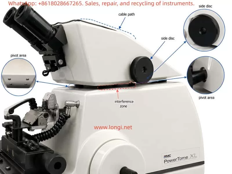
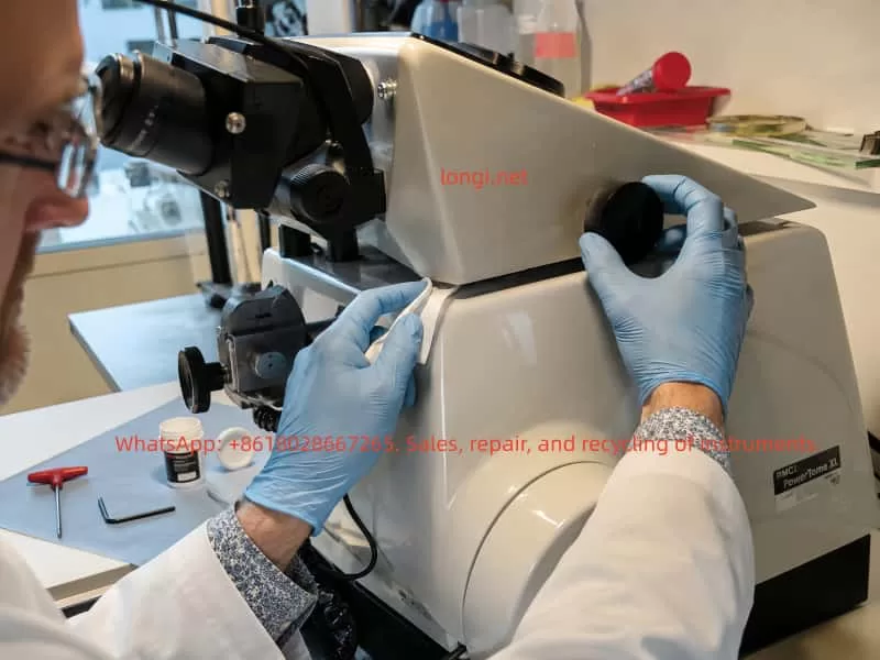
On systems such as the RMC PowerTome XL, the stereomicroscope is mounted on an adjustable support assembly that can be moved laterally or rotated to provide a suitable viewing angle. Under normal conditions, this holder should move smoothly across its working range while still maintaining enough friction to remain stable in the selected position.
A common problem on older ultramicrotomes is that the stereomicroscope holder becomes stiff, uneven, or difficult to move. In some cases, the holder may rotate freely on both sides but become noticeably resistant only when it approaches the central position, approximately parallel to the main longitudinal axis of the instrument.
This type of symptom is important because it does not always indicate a simple lack of lubrication in the vertical pivot. When resistance appears only at one particular angle, the cause is often related to local mechanical interference, internal cable tension, misalignment, or a binding linkage rather than a uniformly dry rotation shaft.
This article explains the mechanical logic behind this fault, describes likely causes, and provides a structured troubleshooting and maintenance approach for stereomicroscope holder rotation problems on ultramicrotomes.
1. Function of the Stereomicroscope Holder
During ultrathin sectioning, the operator must accurately observe the relationship between the specimen block and the knife edge. The stereomicroscope is used to inspect:
- Specimen trimming progress
- Knife edge position
- Clearance angle
- Water boat condition
- Floating section ribbons
- Section compression
- Knife contamination
- Section collection area
For this reason, the stereomicroscope holder must allow comfortable positioning without excessive force. At the same time, the holder must remain stable once the desired observation angle has been selected.
A properly functioning holder should have the following characteristics:
- Smooth movement over the full rotation range
- Light but controlled friction
- No sudden increase in resistance
- No metal-to-metal rubbing noise
- No cable pulling or twisting
- No visible movement of the microscope when the holder is stationary
- Stable positioning without drifting or swinging back
The ideal mechanical condition is not “completely loose.” A well-designed holder usually has a small amount of intentional friction or damping so that the microscope remains where the operator places it.
2. Common Mechanical Designs Used in Microscope Holders
The mechanical design of microscope holders varies between manufacturers and instrument generations. However, most designs fall into several general categories.
2.1 Single Vertical Pivot Design
The simplest design uses a central vertical shaft mounted in a bushing or bearing. The microscope support rotates around this vertical axis.
The assembly may include:
- Vertical steel shaft
- Bronze or polymer bushing
- Thrust washer
- Friction disc
- Spring washer
- Adjustment screw
- Locking screw
- Retaining collar
In this type of system, dried grease or excessive preload usually causes resistance across the entire rotation range.
2.2 Dual-Side Support or Synchronized Adjustment Design
Some ultramicrotomes use a more complex holder structure with two external side discs, knurled wheels, or adjustment knobs. These may be connected internally through a shaft, linkage, cam system, or friction mechanism.
The visible black discs may not be simple locking knobs. They may be part of a synchronized lateral viewing system or a mechanical support structure for the stereomicroscope holder.
Possible internal components include:
- Connecting shafts
- Cam followers
- Friction discs
- Eccentric mechanisms
- Linkage rods
- Gear segments
- Retaining collars
- Compression springs
- Position stops
In such systems, a problem that occurs only at one angle may be caused by internal binding rather than a dry central axis.
2.3 Combined Sliding and Rotating Support Systems
Some holders include both lateral travel and rotational movement. These may use guide rails, sliding blocks, pivot joints, or adjustable friction pads.
Over time, hardened grease, dust accumulation, corrosion, or mechanical misalignment may cause uneven movement.
2.4 Holder Assemblies with Internal Wiring
Modern stereomicroscope holders may contain or guide several cables, including:
- Microscope illumination wires
- Camera cables
- LED power cables
- Video output cables
- Fiber-optic light guides
- Sensor wiring
- Internal control harnesses
These cables move with the holder. If they are routed incorrectly, trapped inside the support, or too tight, they can create resistance at a specific point in the rotation travel.
3. Why Localized Resistance Is an Important Clue
One of the most useful diagnostic details is whether the resistance is uniform or localized.
If the holder feels stiff through the entire movement range, likely causes include:
- Dried grease
- Corroded pivot shaft
- Tight friction adjustment
- Overloaded spring washer
- Worn bushing
- Excessive mechanical preload
- Contaminated thrust surface
However, if the holder moves relatively freely on both sides and becomes difficult only near the central position, the diagnosis changes.
Localized resistance usually suggests one of the following:
- A cable is being stretched or compressed
- A mechanical stop is contacting too early
- A linkage is binding at its center position
- A cam or friction plate is misaligned
- A support component is touching the instrument housing
- An internal wire harness is trapped
- A retaining collar is offset
- The holder assembly is slightly distorted
- A side adjustment mechanism is becoming tight at a specific geometry
This distinction is critical. Adding oil to a pivot will not solve a cable-routing problem, a misaligned cam, or a mechanical interference issue.
4. Typical Failure Modes
4.1 Hardened or Aged Lubricant
Lubricants gradually age. Grease may become thick, dry, sticky, or contaminated by dust. In humid or coastal environments, corrosion can also accelerate degradation.
Typical symptoms include:
- Stiff movement across the full rotation range
- Rough or dry feeling during movement
- Resistance increasing in cold conditions
- Slight improvement after repeated movement
- Uniform friction in both directions
The correct repair normally involves disassembly, removal of old grease, cleaning of the shaft and bushing, inspection for damage, and application of a thin layer of suitable precision lubricant.
4.2 Excessive Friction Adjustment
Many support systems include a friction adjustment mechanism to prevent the microscope from moving unintentionally.
If this adjustment becomes too tight, the holder may become difficult to rotate. Causes include:
- Adjustment screw tightened too much
- Spring washer compressed excessively
- Friction pad swollen or distorted
- Incorrect reassembly after previous service
- Retaining collar moved from its original position
In some systems, the friction is not perfectly uniform. A cam, offset washer, or eccentric component may cause higher resistance near one position.
4.3 Internal Cable Tension
Internal cable tension is one of the most overlooked causes of localized resistance.
A cable may be pulled tight when the holder reaches a certain angle. The cable may then act like a spring, pulling the holder back or creating a noticeable resistance zone.
Signs of cable-related resistance include:
- Holder moves freely on one side but tightens near the center
- Resistance changes if cables are moved by hand
- Visible cable stretching or twisting
- Resistance stronger in one direction than the other
- No obvious grinding sound
- Holder tends to return slightly after release
Cable problems may occur because of:
- Incorrect cable routing
- Lost cable clamp
- Cable tie installed too tightly
- Aged stiff cable insulation
- Excessive cable shortening during previous repair
- Internal harness trapped between moving parts
4.4 Mechanical Interference with the Housing
If the holder or support structure has shifted slightly, it may contact the main instrument housing at a particular angle.
This may be caused by:
- Instrument impact during transport
- Loose mounting screws
- Deformed sheet-metal cover
- Bent support bracket
- Misaligned bearing housing
- Previous incorrect assembly
- Wear in the pivot bushing
Visible clues may include:
- Paint scratches
- Bright metal rubbing marks
- Plastic dust
- Black powder from friction surfaces
- Uneven gaps between the holder and instrument body
- Contact marks near the pivot region
4.5 Binding in a Dual-Side Adjustment Mechanism
When a holder has large side discs or synchronized wheels, the mechanism may include a complex internal transmission system.
Potential faults include:
- Dry cam surface
- Misaligned synchronizing shaft
- Loose retaining screw
- Damaged friction disc
- Uneven spring tension
- Bent internal linkage
- Worn or cracked plastic bushing
- Binding gear segment
- Offset eccentric mechanism
This type of problem often produces localized resistance because the mechanical geometry changes during rotation.
5. Why Oil Should Not Be Applied Immediately
It is tempting to apply oil directly into a visible gap around the rotation axis. However, this is not recommended until the fault source has been confirmed.
Several risks exist.
5.1 Oil Can Enter Sensitive Areas
Low-viscosity oil may migrate into:
- Microscope optics
- Knife area
- Sample stage
- Internal electronic components
- Friction pads
- Cable channels
- Instrument housing
Once oil migrates, it can collect dust and create sticky deposits.
5.2 Penetrating Sprays Can Remove Original Grease
Products such as general-purpose penetrating sprays may temporarily reduce friction, but they can also dissolve or displace the original grease. This may leave internal components poorly protected after the solvent evaporates.
5.3 Excess Lubricant Can Create New Problems
Too much grease or oil can:
- Attract dust
- Increase contamination risk
- Spread into the cutting area
- Affect friction adjustment
- Cause the holder to become too loose
- Stain laboratory surfaces or specimens
5.4 Lubrication Will Not Fix Mechanical Interference
If the real problem is a trapped cable, a rubbing housing, or a binding linkage, oil will not solve it. It may only hide the issue temporarily.
6. Recommended Inspection Procedure
Before considering disassembly, the following inspection procedure should be followed.
Step 1: Make the Instrument Safe
Before handling the holder:
- Switch off the instrument
- Disconnect power if necessary
- Remove the knife or move it to a safe position
- Remove the specimen block if possible
- Protect the cutting area
- Ensure the holder cannot swing into the knife assembly
Ultramicrotome knives are extremely sharp. Even minor movement of the microscope holder can create an accident risk if the knife is exposed.
Step 2: Identify the Exact Tight Position
Move the holder slowly through its full travel and record:
- Where the resistance begins
- Whether the resistance is repeatable
- Whether it is stronger when moving left-to-right or right-to-left
- Whether the holder stops suddenly or gradually
- Whether any rubbing sound is present
- Whether the holder moves more easily when lifted slightly
If the resistance always occurs at the same position, this strongly indicates a geometry-related issue rather than random lubrication failure.
Step 3: Inspect Cables and Wiring
Carefully check:
- Microscope rear cables
- Illumination cables
- Fiber-optic light guides
- Camera wiring
- Cable loops behind the holder
- Cable routing under the support
- Wiring near the side adjustment discs
- Any wires entering the main housing
At the tight position, inspect whether any cable becomes:
- Straightened
- Twisted
- Compressed
- Pulled against a sharp edge
- Pinched between moving parts
- Tensioned around the pivot
A cable may be hidden inside the support housing, so visible external wiring should not be assumed to be the only source.
Step 4: Check for Contact Marks
Inspect the holder and surrounding housing for:
- Scratched paint
- Polished metal contact areas
- Plastic rubbing marks
- Wear debris
- Uneven clearances
- Deformed covers
- Loose panels
Mechanical interference often leaves visible evidence.
Step 5: Test the Side Adjustment Discs
If two large side discs or knurled wheels are present, compare their behavior at different holder positions.
Check:
- Are both discs equally easy to turn?
- Do they become tight when the holder reaches the difficult central position?
- Does turning one disc affect the other?
- Is there any slipping, clicking, or irregular motion?
- Does one disc have significantly more resistance than the other?
If the discs also become stiff near the same position, the problem is likely inside the synchronized adjustment mechanism.
If the discs remain smooth but the holder itself becomes difficult to swing, the problem is more likely related to the main pivot, cable routing, or housing interference.
7. Components That Should Not Be Removed First
Without a detailed service manual or exploded drawing, several components should not be removed casually.
These include:
- Large black knurled side discs
- Center screws inside the side discs
- Retaining screws supporting the holder assembly
- Bottom screws that may hold the entire support structure
- Screws near internal spring or friction mechanisms
- Any screw that appears to retain a shaft
Removing these parts may cause:
- Misalignment of the microscope holder
- Loss of synchronization between both sides
- Release of springs or friction washers
- Shift of the rotation center
- Loss of stable positioning
- Difficulty restoring original adjustment
- Damage to internal cable routing
Before removing any screw, the support structure should be properly supported and photographs should be taken from multiple angles.
8. Proper Lubrication Method
If inspection confirms that the pivot shaft or bushing is genuinely dry or contaminated, lubrication should be performed correctly.
The goal is not to flood the mechanism with oil. The goal is to restore a thin, stable lubricating film.
A suitable lubricant should have:
- Low evaporation rate
- Good metal compatibility
- Good plastic compatibility
- Stable behavior over time
- Low migration tendency
- Appropriate viscosity
- Resistance to humidity and oxidation
Suitable choices may include precision synthetic grease or PTFE-compatible instrument grease, depending on the materials involved.
A typical lubrication procedure includes:
- Remove the holder assembly carefully.
- Photograph all components before disassembly.
- Clean old grease from the shaft, bushing, thrust washers, and friction surfaces.
- Inspect for corrosion, scoring, burrs, cracks, or uneven wear.
- Apply a very thin layer of suitable grease.
- Reassemble in the original order.
- Adjust preload gradually.
- Test movement across the full rotation range.
- Confirm that the holder remains stable but not excessively tight.
Excess lubricant should always be removed. The mechanism should not have visible grease squeezing out around the pivot.
9. When Professional Service Is Recommended
Professional service should be considered when any of the following conditions are present:
- The holder binds strongly at one position
- The holder produces metal scraping sounds
- The side adjustment discs are not synchronized
- The holder has vertical play or wobble
- The holder suddenly releases after resistance
- Internal cables appear to be trapped
- The support structure touches the instrument housing
- The holder is difficult to reassemble after partial disassembly
- The instrument has high-value optical or cutting accessories
- The mechanism includes hidden springs, cams, or friction components
Although the fault may appear minor, incorrect disassembly can affect the microscope position, viewing geometry, cable routing, and long-term usability of the ultramicrotome.
10. Conclusion
A stiff stereomicroscope holder on an ultramicrotome should not automatically be treated as a lubrication problem.
When the holder is difficult to move only near the central position, the most likely causes are localized mechanical interference, cable tension, internal linkage binding, misalignment, or non-uniform friction adjustment.
The correct diagnostic approach is:
- Identify whether resistance is uniform or localized.
- Inspect cables and external contact points.
- Check for housing interference and wear marks.
- Compare the behavior of side adjustment mechanisms.
- Avoid unnecessary disassembly.
- Lubricate only after confirming that the pivot or bushing is the true source of the problem.
A careful inspection sequence can prevent unnecessary damage and reduce the risk of contaminating a precision ultramicrotome with unsuitable lubricants. Proper diagnosis is more important than immediately applying oil, especially when the symptom is angle-dependent rather than constant.