Posted on

The “Time Bomb” of Frequency Converters: The Hidden Payment Rules and Industry Chronic Illness Behind the E.rH5 Fault of the D1M Series

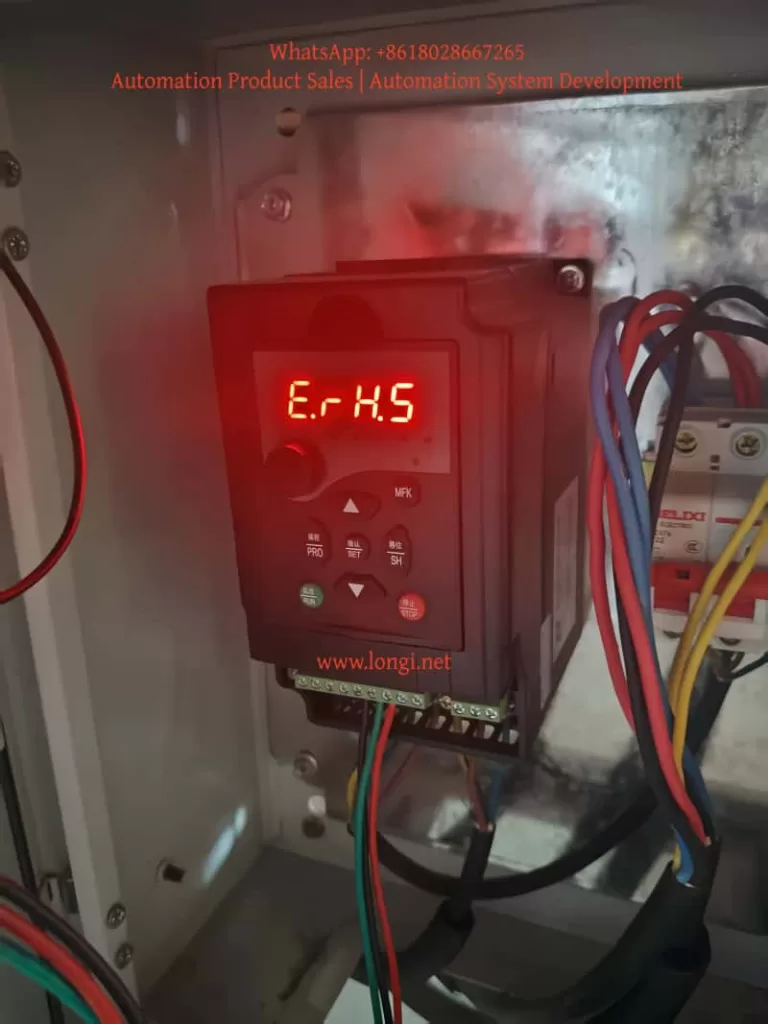
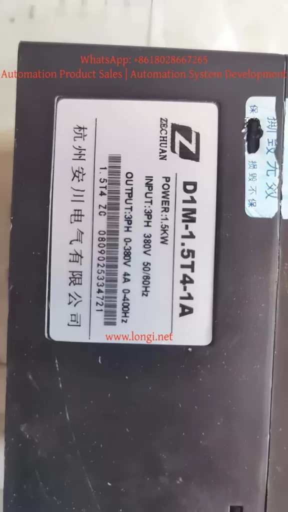
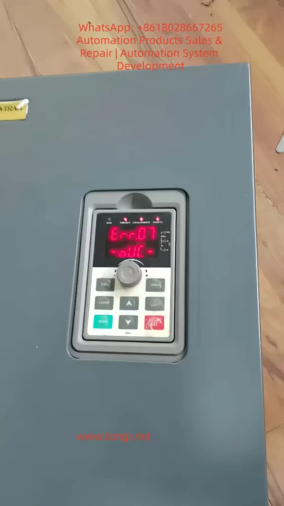
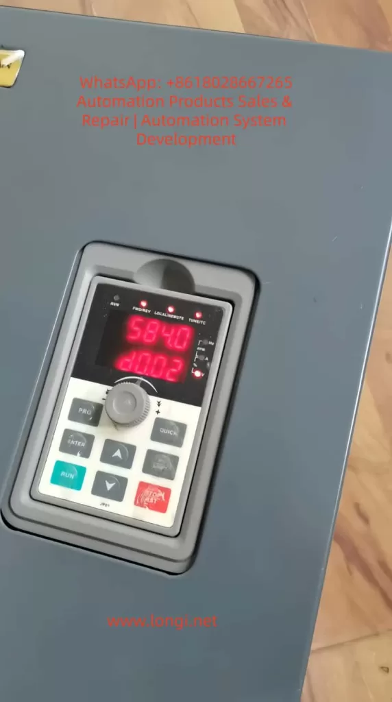
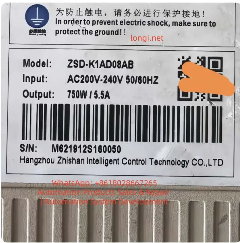
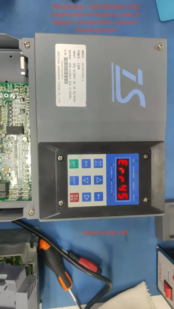
The Hangzhou Yaskawa D1M – 1.5T4 – 1A frequency converter, a domestically – produced simple device with a nominal power of 1.5 kW, an input of 3PH 380V 50/60Hz, and an output of 0 – 400Hz, showed the “E.rH5” display on its digital tube immediately after being powered on at the user’s site. The device was completely locked up, unable to start, modify parameters, or run any motor load. The user searched through the entire 32 – page PDF “User Quick Manual” (Version 1.1, August 8, 2014), from the table of contents to Chapter 4 “Maintenance and Fault Information”, including 4.1 “Fault Information and Troubleshooting” and 4.2 “Common Abnormal Phenomena”. However, the list of all fault codes in the manual did not include E.rH5. The manual only listed conventional protections such as over – voltage, under – voltage, over – current, and over – heating, but remained silent about this error. When the user contacted the manufacturer, the first response was “Find the dealer who sold you the device.” The dealer replied that this was a pre – set “usage period lock” at the factory. Once the period expired, the device would be forced to shut down, and it could only be restored by an authorized dealer entering an unlock code. In essence, this was a “time bomb” implanted by the manufacturer to control the dealer’s payment collection.

E.RH.5 OR E.RH.S fault

This practice is not an isolated case but an open – secret in the current domestic low – end frequency converter market, especially for simple series like D1M and X5M. It is directly derived from the “lease control” model in the PLC industry from the late 1990s to the early 2000s. At that time, many small and medium – sized PLC manufacturers embedded real – time clocks (RTCs) or counters in their programs to recover project final payments. If the final payment was not settled after project acceptance, the PLC would enter a read – only or shutdown state, and users could only unlock it through the manufacturer’s backend. Now, with a deteriorating market environment, the frequency converter industry has directly replicated this logic at the hardware level. During factory programming, manufacturers write a hidden parameter (usually an encrypted internal counter or a countdown based on the built – in RTC of the main control chip) into the EEPROM or Flash. Users cannot see this during normal use, and it only triggers a specific hidden error code (such as E.rH5) when it expires. The manual deliberately omits it to prevent end – users from (cracking) it on their own, forcing them to (obediently) seek paid unlocking from dealers.

Technically, it is not a complex implementation. The low – cost main control chips (commonly ST or domestic MCUs) used in the D1M series support RTCs or software timers. Manufacturers only need to pre – set an “authorization duration” variable (e.g., 180 days or 365 days) in the factory firmware, along with a simple CRC check or simple encryption. During power – on self – check, it compares the current timing. Once it exceeds the set time, it directly jumps to a lock – up sub – program, blocking all operation commands and displaying the pre – set hidden code on the panel. In the “Basic Function Parameters” and “Protection Function Parameters” tables in the manual, there are no parameter groups related to “usage period” at all, because this is a “backdoor” left by the manufacturer for dealers. This design has extremely low costs but fully transfers the payment collection risk to dealers and end – users. When dealers purchase goods, manufacturers often supply them on a “installment” or “account period” basis, but at the same time require dealers to bind a period lock on the devices. When end – users buy the devices, if dealers default on payments to manufacturers, manufacturers may remotely lock the devices through dealers or directly, creating a layer – by – layer transfer of risk.

D1M-1.5T4-1A

The current macro – environment has exacerbated this practice. Since 2023, the domestic low – voltage frequency converter market has suffered from severe overcapacity, and the price war has become extremely fierce. The factory price of a 1.5 kW three – phase model has dropped to the 200 – 300 yuan range, and dealers’ gross profits have been compressed to almost zero. At the same time, small and medium – sized enterprises have highly volatile orders and long payment collection cycles. Manufacturers are worried that dealers will accumulate inventory and then run away, so they use the “time lock” as a payment collection insurance. As a result, end – users have become the ultimate victims. A knitting factory, a small packaging machinery factory, or a logistics door equipment factory may spend thousands of yuan to buy the device, install and debug it, and be ready for mass production when suddenly the E.rH5 code appears on the panel, the motor stops, and the production line is paralyzed. When users contact the manufacturer, the manufacturer refers them to the dealer. When they contact the dealer, the dealer either asks for a price difference to unlock it or directly states that it is “manufacturer’s policy.” There is no contract agreement or prior notice in the whole process. It is simply a case of “buying is equivalent to renting.”

What is even more egregious is that this lock – up mechanism directly violates the integrity of ownership after product delivery. After users pay the full amount, the ownership of the device has been transferred, but they are still controlled by the manufacturer through a firmware backdoor regarding the operation right. This is similar to digital rights management (DRM) in the software industry but lacks any legal authorization agreement. Users only see an ordinary commodity when making a purchase but end up with a “hardware with a limited service life.” The manual repeatedly emphasizes “Only qualified professionals can install and debug” and “Please use it correctly according to the manual” but deliberately conceals the most critical restrictive clauses, which is a typical case of information asymmetry fraud. In case of disputes, it is extremely difficult for users to defend their rights: the fault code is not in the manual, the manufacturer does not admit it as a quality issue but only as a “commercial policy,” and it is also difficult for the court to determine it as a product quality liability.

This phenomenon has spread among multiple domestic simple frequency converter brands. Series such as Wanxin X5M, Taichuang D1M, and Hangzhou Yaskawa D5M are essentially different re – branded products on the same technical platform, targeting cost – sensitive fields such as knitting machinery, small and medium – sized mechanical equipment, and constant – pressure water supply. These fields have a large number of users, low unit prices, and high replacement costs, making them the most likely targets for “lock – up.” In contrast, regular Japanese brands (such as the real Yaskawa Electric) or high – end domestic brands have never had such hidden lock – up functions. They compete based on technology, reliability, and service rather than using backdoors to control payment collection. However, the low – end market uses such “unpleasant functions” as a competitive weapon. Although it may help manufacturers and dealers tide over difficulties in the short term, it will completely destroy the industry’s reputation in the long run. Once users have a bad experience, they will develop a trust crisis towards all domestic frequency converters and turn to imported or more transparent brands, ultimately compressing the living space of the entire domestic supply chain.

To break this cycle, multiple parties need to take action. First, users must require manufacturers or dealers to provide a “no usage period lock” commitment letter when making purchases and immediately perform a full parameter backup and long – term power – on test (at least run for the pre – set period) after the device arrives. Second, dealers should jointly resist the lock – up requirements imposed by manufacturers and promote the industry association to issue clear regulations: the factory firmware must disclose all hidden parameters, and operation restrictions without written notice are prohibited. Third, manufacturers themselves should reflect. In today’s price war that has reached the bottom line, relying on backdoors to maintain cash flow is like drinking poison to quench thirst. Only by focusing on improving heat dissipation design, optimizing vector control algorithms, reducing harmonics, and enhancing EMC performance can they truly win the market. The positioning of the D1M as a “simple frequency converter with high cost – effectiveness, simple and practical” should have been a breakthrough for domestic substitution, but it has self – destructed due to a “time bomb.”

On a deeper level, this reflects the dilemma of Chinese manufacturing industry’s internal competition at the low – end of the industrial chain. Under the pressure of economic downturn, enterprises, in order to survive, are willing to sacrifice user experience and long – term reputation. Similar phenomena are also emerging in other industrial automation components: some contactors and servo drives are also starting to have “paid activation” or “cloud – based locks.” If this is allowed to continue, the underlying trust foundation of Industry 4.0 and smart manufacturing will collapse. Users are not fools; they will vote with their feet: they would rather spend more money on a device that “guarantees permanent operation” than touch a “cheap product” that may be locked up halfway.

The E.rH5 fault of the Hangzhou Yaskawa D1M is just the tip of the iceberg. It reminds us that technology is never neutral. A simple counter in embedded software can turn an industrial device into “leased hardware.” Manufacturers, dealers, and users must return to the spirit of contract: clear pricing,信息公开 (information disclosure), and full ownership upon delivery. Otherwise, the low – end frequency converter market will only become more and more “competitive in a vicious way,” and in the end, there will only be “zombie devices” that are locked up with each other and ( can be translated as “lost” here, referring to lost users) users. True competitiveness always comes from the product itself, not from backdoors hidden in the firmware.

Posted on

In-Depth Analysis and Comprehensive Troubleshooting Guide for ERR14 Module Overheating Fault in Ruichi RC-9 Series Inverters

Foreword

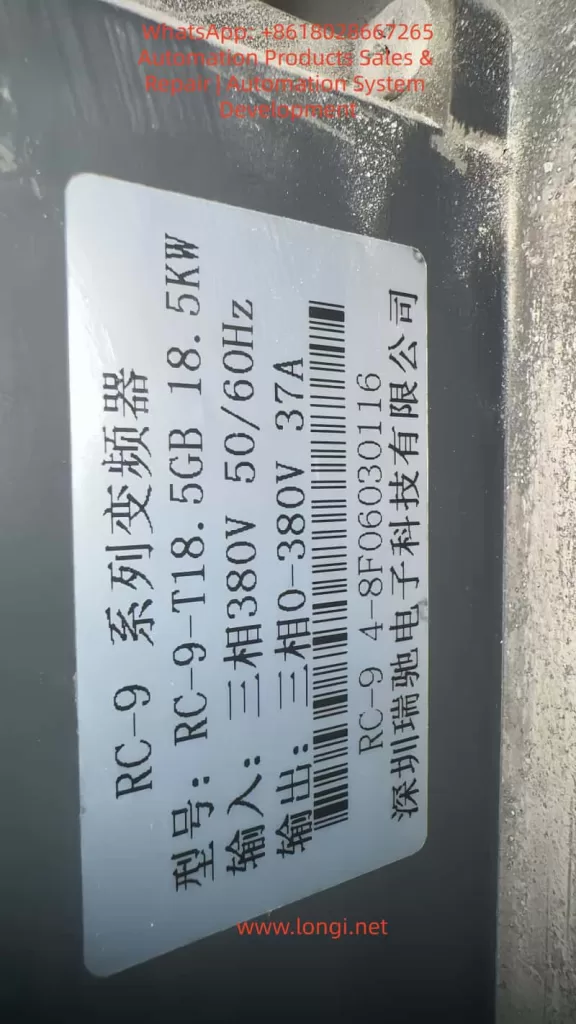
The Ruichi RC-9 series, a high-performance vector-type inverter launched by Shenzhen Ruichi Electronics, is widely used in various industrial automation scenarios such as textiles, machine tools, building materials, fan and pump systems, and lifting and conveying systems. It features both V/F and vector control modes, a wide speed regulation range, high starting torque, and rich networking capabilities. Among them, the RC-9-T18.5GB model with an 18.5kW rating is a core device in small- to medium-power industrial drive systems.

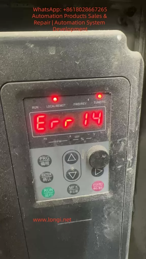
During long-term operation in the field, the ERR14 fault code is one of the most frequently occurring fault types in the RC-9 series inverters. This fault represents overheating protection for the inverter’s core power device module. Once triggered, the inverter immediately blocks its output and shuts down for protection, which not only directly interrupts the production process but also causes permanent degradation or even breakdown of the IGBT (Insulated Gate Bipolar Transistor) inverter module due to repeated overheating impacts. In severe cases, it can lead to catastrophic failures such as inverter explosions.

Based on the technical specifications in the official user manual of the RC-9 series inverters and combined with practical maintenance experience in industrial settings, this article provides an in-depth analysis of the underlying triggering logic and core causes of the ERR14 fault. It establishes a standardized, step-by-step troubleshooting and resolution process and proposes a systematic preventive maintenance plan. This guide offers directly applicable technical guidance for equipment maintenance personnel to fundamentally reduce the occurrence probability of this fault and ensure the long-term stable operation of drive systems.

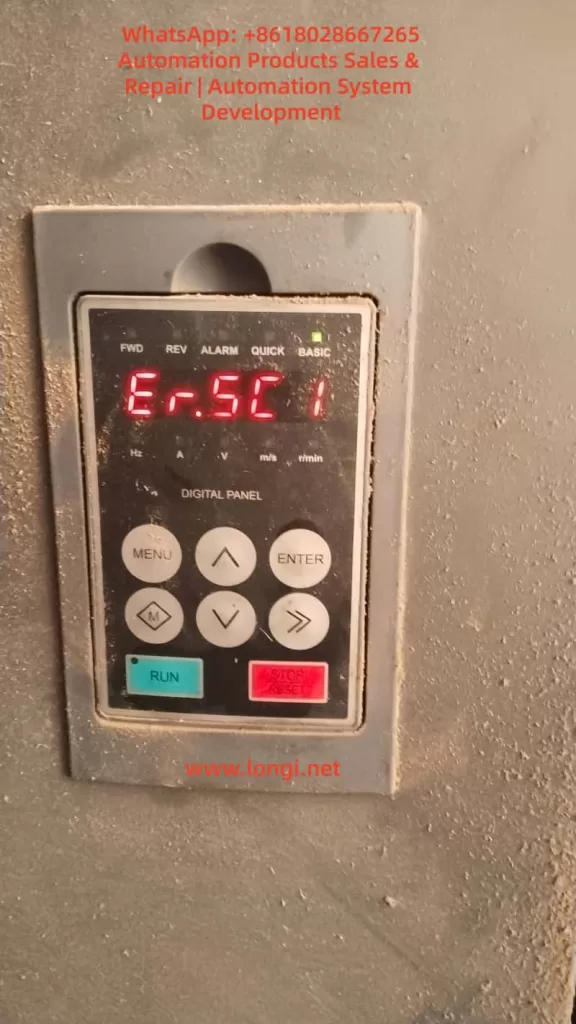
Err 14 fault

I. Core Definition and Underlying Protection Logic of the ERR14 Fault

In the fault code system of the Ruichi RC-9 series inverters, ERR14 is officially defined as an inverter module overheating fault. It represents a hardware + software dual-level protection mechanism implemented by the inverter for the core power device, the IGBT. This fault is classified as a highest-priority shutdown protection type.

The IGBT module is the core component of the inverter responsible for converting alternating current (AC) to direct current (DC) and then back to adjustable-frequency and adjustable-voltage AC power. During its operation, two primary types of losses occur: conduction losses when the IGBT is in the conducting state and switching losses during state transitions. All these losses are ultimately dissipated in the form of heat. As a semiconductor power device, the performance and lifespan of an IGBT are directly related to its operating temperature. The industry consensus is that for every 10°C increase in the IGBT junction temperature, the device’s lifespan is halved. When the junction temperature exceeds the chip’s rated tolerance threshold, it directly causes irreversible thermal breakdown of the chip, leading to permanent damage to the module.

Based on this, the RC-9 series inverters integrate high-precision NTC (Negative Temperature Coefficient) thermistors within the IGBT module. Through the sampling circuit on the drive board, the module’s case temperature data is continuously collected and transmitted to the main control board for real-time monitoring. The factory-default module overheating protection threshold for the inverter is set at 75°C (adjustable within the range of 0-100°C via function code P8-47). When the temperature sampling circuit detects that the IGBT module temperature reaches the protection threshold, the main control board immediately triggers the ERR14 fault protection, blocks the IGBT drive signals, stops the inverter output, activates the fault relay, illuminates the fault indicator on the panel, and displays the ERR14 fault code, providing rapid protection for the IGBT module.

It is important to note that ERR14 faults can be categorized into two types: genuine overheating faults triggered by actual overheating of the IGBT module and false alarms caused by abnormalities in the temperature sampling circuit. The former results from the actual temperature of the IGBT module exceeding the limit, while the latter is caused by incorrect protection triggered by damage to the temperature sensing element or the sampling circuit. The troubleshooting approaches for these two types are entirely different, and this distinction is a common source of misjudgment in field maintenance.

II. In-Depth Analysis of the Five Core Causes of ERR14 Module Overheating Faults

Based on the hardware design, user manual specifications, and field maintenance data of the RC-9 series inverters, the triggering of ERR14 faults can be attributed to five core causes that cover the entire chain of factors from the external environment and mechanical cooling to electrical parameters and hardware components. Over 80% of these faults are concentrated in the first three external and cooling-related causes.

(I) Excessive Operating Environment Temperature Exceeding Inverter Design Tolerance

The standard designed operating environment temperature range for the RC-9 series inverters is -10°C to 50°C, with a maximum allowable ambient temperature of 50°C under rated load conditions. When the ambient temperature exceeds this range, the inverter’s cooling capacity drops sharply, directly causing overheating of the IGBT module and triggering the ERR14 fault.

Common scenarios where the ambient temperature exceeds the limit include:

  • The inverter is installed inside a closed electrical control cabinet without a properly designed cooling air duct or without additional cooling equipment such as cooling fans or air conditioners. The heat generated by the inverter’s operation accumulates continuously within the cabinet, creating a “heat island effect.” In high-temperature workshops during summer, the cabinet temperature can easily exceed the 50°C threshold.
  • Multiple inverters are stacked vertically inside the cabinet without installing thermal insulation and airflow guide plates as specified in the manual. The hot air exhausted by the lower inverter is directly drawn into the air intake of the upper inverter, creating a hot air circulation loop that renders the cooling system ineffective.
  • The inverter is installed in a location exposed to direct sunlight or near external heat sources such as boilers, heating furnaces, or resistance boxes, causing the ambient temperature to rise passively.
  • The installation site has high humidity or corrosive gases, which not only accelerate device aging but also reduce insulation performance, indirectly increasing device leakage currents and exacerbating heat generation.

According to the installation specifications for the RC-9 series inverters, for models with a rated power greater than 22kW, a vertical installation spacing of ≥200mm is required. For models with a rated power of 18.5kW and below, a vertical spacing of ≥100mm and sufficient lateral cooling space are required. Field maintenance data shows that non-compliance with these installation specifications and poor environmental cooling conditions are the most common诱因 (causes) for ERR14 faults.

(II) Blocked Cooling Air Duct, Sharp Decline in Heat Sink Heat Exchange Efficiency

The RC-9 series 18.5kW model adopts a cooling structure consisting of an IGBT module in direct contact with an aluminum heat sink and a bottom-mounted axial fan for forced air cooling. The designed air duct follows a bottom-in, top-out pattern, where the fan drives air to flow through the heat sink fins, carrying away the heat generated by the IGBT module. The heat exchange efficiency of the heat sink directly determines the effectiveness of temperature control for the IGBT module, and air duct blockage is the most common cooling failure issue in the field.

In scenarios with high levels of dust, cotton fibers, or metal chips, such as cement and building materials production, textile and chemical fiber manufacturing, mining, and woodworking, the inverter continuously operates, and airborne particulate matter continuously adheres to the spaces between the heat sink fins and the air intake filter screen. Especially for the 18.5kW model, which has relatively small fin spacing on the heat sink, the fins can easily become completely blocked by particulate matter, forming a “thermal insulation layer.” In this case, even if the fan operates normally, air cannot flow through the heat sink fins to form convection, causing the heat exchange efficiency of the heat sink to drop by over 80%. The heat generated by the IGBT module cannot be dissipated, and its temperature can rise rapidly to the protection threshold within a few minutes, triggering the ERR14 fault.

Additionally, when oil and moisture adhere to the surface of the heat sink, they combine with dust to form oil sludge, which not only blocks the air duct but also significantly reduces the thermal conductivity of the heat sink, further worsening the cooling effect. This is a core cause of ERR14 faults in scenarios with high levels of oil and grease, such as food processing and metalworking.

(III) Failure of the Cooling Fan System, Complete Loss of Forced Air Cooling Function

The cooling fan is the core power component of the forced air cooling system in the RC-9 series inverters, and its operating status directly determines the effectiveness of the cooling system. According to the user manual’s specifications for replacing consumable parts, the designed service life of the cooling fan is 2-3 years. After long-term operation, the fan is prone to aging and failure, making it a high-frequency诱因 (cause) of ERR14 faults.

The main forms of cooling fan system failure include:

  • Wear and aging of the fan bearings, resulting in reduced rotational speed, shutdown, abnormal noise during operation, and a significant decrease or complete loss of air volume. As a result, the heat sink cannot form effective convection.
  • Severe dust accumulation on the fan blades, fractures, or defects, causing a loss of dynamic balance and substandard air pressure and volume that cannot meet the cooling requirements of the heat sink.
  • Faults in the fan power supply circuit, including loose or oxidized connection terminals, blown fuses in the power supply, or damage to the fan power supply circuit on the drive board, preventing the fan from starting up when powered on.
  • Incorrect settings for the fan control parameters. The RC-9 series inverters use function code P8-48 to set the cooling fan control mode, with a factory default value of 0 (fan operates during inverter operation). If it is mistakenly set to other modes, the fan may not start up when the inverter is running, directly causing an overheating fault. If it is set to 1 (fan always operates) for an extended period, it accelerates bearing aging and shortens the fan’s service life.

Field maintenance data shows that for RC-9 series inverters with an operating life exceeding 2 years, failures caused by fan issues account for over 60% of ERR14 faults. Moreover, most of these faults are preceded by warning signs such as abnormal fan noise or reduced rotational speed, which are often not addressed in a timely manner during maintenance.

RC-9-T18.5GB

(IV) Abnormalities in the Temperature Sampling Circuit, Triggering False Overheating Alarms

If the inverter triggers the ERR14 fault under low-temperature environmental conditions or during no-load operation, and no abnormalities are found in the heat sink or fan, there is a high probability of abnormalities in the IGBT module’s temperature sampling circuit, causing the main control board to receive incorrect high-temperature signals and trigger false protection. This is a cause that is easily overlooked and prone to misjudgment in field maintenance, leading many maintenance personnel to mistakenly conclude that the module is damaged and incur unnecessary costs for replacing spare parts.

The temperature sampling circuit in the RC-9 series inverters consists of three parts: the NTC thermistor built into the IGBT module, connection terminals and wiring harnesses, and the temperature sampling circuit on the drive board and main control board. Abnormalities in any of these parts can lead to incorrect temperature sampling.

  • Damage or aging of the NTC thermistor: The NTC thermistor is a negative temperature coefficient device with a nominal resistance of mostly 10kΩ at a normal temperature of 25°C. After long-term operation at high temperatures, it may experience resistance drift, open circuits, or short circuits. If the resistance becomes abnormally low, it will transmit false high-temperature signals to the main control board, triggering a false ERR14 alarm.
  • Faults in the wiring and transmission circuit: Loose or oxidized connection terminals of the thermistor, broken wires, or poor contact in the 32-pin wiring harness between the drive board and the main control board can interrupt or distort the temperature sampling signals, causing false alarms.
  • Hardware damage in the sampling circuit: Faults in the temperature sampling circuit on the drive board or main control board, including changes in the values of sampling resistors, damage to operational amplifiers, or failure of filtering capacitors, can lead to abnormal temperature sampling data and trigger protection actions.

(V) Performance Degradation/Damage of the IGBT Inverter Module Itself, Exacerbating Abnormal Heat Generation

When all the above external factors have been ruled out and the ERR14 fault still occurs frequently, the core cause is performance degradation or physical damage to the IGBT inverter module itself, resulting in significantly higher heat generation than normal during operation and triggering overheating protection.

The degradation and damage of IGBT modules mainly result from the following scenarios:

  • Long-term operation under heavy loads and frequent starting and stopping, especially when the 18.5kW inverter is used for impact loads such as cranes, mixers, and wire drawing machines. The IGBT is subjected to high current impacts for extended periods, causing fatigue in the chip solder layer, a significant increase in thermal resistance, and an inability to transfer heat to the heat sink effectively, leading to a rapid rise in junction temperature.
  • Previous occurrences of output short circuits, motor-to-ground short circuits, overcurrent faults, or other issues in the inverter, which caused hidden damage to the IGBT chip. Although these incidents may not directly cause an explosion, they significantly increase the chip’s on-resistance. Under the same load current, the conduction losses increase exponentially, leading to a sharp increase in heat generation.
  • Aging of the freewheeling diodes within the module, resulting in a significant increase in reverse leakage current and generating additional heat.
  • Drying out or脱落 (detachment) of the thermal conductive silicone grease between the module and the heat sink, or loosening of the fixing screws, creating air gaps between the module and the heat sink and causing a sharp increase in thermal resistance, rendering the cooling ineffective.

The performance degradation of IGBT modules is irreversible. If not addressed promptly, not only will ERR14 faults occur frequently, but it will eventually lead to module breakdown, inverter explosions, and even damage to core components such as the main control board and drive board, resulting in greater economic losses.

III. Step-by-Step Troubleshooting and Standardized Resolution Process for ERR14 Faults

In response to the five core causes of ERR14 faults, we have developed a step-by-step troubleshooting and resolution process that progresses from easy to difficult, from external to internal factors, and from low-cost to high-cost solutions. This process fully complies with the maintenance logic in industrial settings, helping maintenance personnel quickly locate the root cause of the fault, resolve issues efficiently, and strictly adhere to the safety operation specifications of the RC-9 series inverters to avoid risks such as electric shock and secondary damage to the equipment.

Step 1: Initial Fault Assessment and Safety Operation Specifications (Prerequisite)

After the inverter triggers the ERR14 fault, the following operations must be performed first. Repeated resetting or forced starting and operation are strictly prohibited to avoid exacerbating the fault:

  • Press the STOP/RES (stop/reset) button on the inverter panel to confirm that the inverter is in a stopped state. Then, disconnect the air circuit breaker on the input side of the inverter to completely cut off the input power supply.
  • Strictly adhere to the safety specifications in the user manual. After powering off, wait at least 2 minutes to allow the bus capacitors inside the inverter to fully discharge. Confirm that the CHARGE indicator is off or use a multimeter to measure that the bus voltage is below AC36V before opening the cover for operation to eliminate the risk of electric shock.
  • Record key fault information, including the operating conditions when the fault was triggered (no-load/full-load, starting process/stable operation/deceleration process), ambient temperature, operating life of the inverter, past maintenance records, and the operable duration after fault reset. This information provides direction for subsequent troubleshooting.

Step 2: Inspection and Rectification of External Environment and Installation Compliance

This step is the priority for troubleshooting and does not require disassembly of the inverter itself. It can resolve most environment-related faults. The core inspection and rectification content is as follows:

  • Ambient temperature measurement and rectification: Use a temperature gun to measure the ambient temperature inside the inverter control cabinet and confirm whether it exceeds 45°C. If it approaches or exceeds the 50°C threshold, take immediate rectification measures: Install axial cooling fans or industrial air conditioners in closed control cabinets, remove heat-generating devices from the cabinet, avoid direct sunlight on the inverter, keep it away from external heat sources, and ensure that the cabinet’s ambient temperature remains stable below 40°C.
  • Compliance check for installation specifications: Check whether the inverter is installed vertically and strictly prohibit inversion or tilting beyond 5°, as this will affect air duct convection. Confirm whether sufficient cooling space is reserved above, below, and to the sides of the inverter. For the 18.5kW model, a vertical spacing of ≥100mm and a lateral spacing of ≥50mm are required. When multiple inverters are installed vertically in a stack, thermal insulation and airflow guide plates must be installed to avoid hot air circulation.
  • Inspection for obstructions at air inlets and outlets: Clear any obstructions at the air inlets and outlets of the inverter and replace clogged air intake filters to ensure smooth air intake and exhaust in the air duct.

Step 3: Inspection and Maintenance of the Cooling Air Duct and Fan System

This step is the core环节 (part) for resolving ERR14 faults, and over 80% of the faults in the field can be resolved through this step. The specific operations are as follows:

  • Thorough cleaning of the cooling air duct: After the inverter is powered off and discharged, remove the top and bottom covers. Use dry compressed air with a pressure ≤0.6MPa to blow dust, cotton fibers, and metal chips out of the heat sink fins from the air outlet towards the air inlet. If there is oil and grease on the heat sink surface, wipe it clean with anhydrous alcohol and allow it to dry completely before reinstalling the covers.
  • Comprehensive inspection and replacement of the cooling fan:
    • Visual inspection: Check for fractures or dust accumulation on the fan blades, abnormal noise from the bearings, and loose or aged connection terminals.
    • Power-on testing: After reinstalling the safety covers and powering on, set function code P8-48 to 1 to force the fan to operate continuously. Check whether the fan starts up normally, feel the air volume at the air outlet with your hand, and use a tachometer to measure the fan speed to confirm whether it meets the rated specifications.
    • Fault handling: If the fan does not rotate, first troubleshoot the power supply circuit and wiring connections, then inspect the fan itself and replace any damaged fans with ones of the same specifications immediately. If the fan has been in operation for more than 2 years, even if it is temporarily operating normally, preventive replacement is recommended to avoid sudden failures in the future.
    • Verification after rectification: After completing the cleaning and fan replacement, restore the inverter’s normal wiring connections, power it on, and run it under no-load conditions. Monitor the IGBT module temperature through the monitoring parameters in the U0 group on the inverter panel. Under normal ambient conditions, the no-load temperature should be 10-20°C higher than the ambient temperature and stabilize between 40-60°C.

Step 4: Inspection and Optimization of Load and Operating Parameter Rationality

If the cooling system is functioning normally but the inverter still triggers the ERR14 fault under load, it is necessary to inspect whether the load conditions and operating parameter settings are reasonable to eliminate additional heat generation caused by improper parameters or overloading:

  • Load current monitoring and overloading inspection: Check the inverter’s output current (monitoring parameter U0-02) through the panel. The rated output current of the RC-9-T18.5GB model is 37A. If the operating current consistently exceeds 90% of the rated value, it indicates heavy-load or overloading operation, which is a core诱因 (cause) of IGBT heat generation. Immediately inspect whether the motor is experiencing stalling, whether the mechanical load is jammed, whether the transmission mechanism is faulty, and whether the inverter selection matches the load. Resolve mechanical faults, reduce the load, and if the inverter is undersized, replace it with a model of a higher power rating.
  • Optimization of carrier frequency parameters: The carrier frequency is set by function code P0-15. A higher carrier frequency reduces motor noise but increases the switching losses of the IGBT, resulting in higher heat generation. For scenarios with high ambient temperatures and frequent ERR14 faults, the carrier frequency can be appropriately reduced within an acceptable range of motor noise. For the 18.5kW model, it can be lowered from the factory default of 8kHz to 4-5kHz, significantly reducing the IGBT’s switching losses and heat generation.
  • Optimization of motor parameters and control modes: If the inverter is operating in vector control mode (SVC/VC) and motor parameter auto-tuning has not been performed, it will result in insufficient control accuracy, large current fluctuations, and increased additional heat generation. Strictly follow the steps in Section 4.2 of the user manual to perform complete tuning (set P1-37=2) with the motor and load completely decoupled. If decoupling the load is not possible, perform static tuning (set P1-37=1) to ensure that the motor parameters match the actual operating conditions and reduce operating current and heat generation.
  • Optimization of V/F curves and torque boost: For V/F control mode, if the torque boost parameter P3-03 is set too high, it will result in excessive no-load current for the motor and increased IGBT heat generation. For square torque loads such as fans and pumps, set P3-02 to 2 (square V/F curve) and reduce the manual torque boost value to eliminate additional losses and heat generation at low speeds.

Step 5: Inspection of Temperature Sampling Circuit Abnormalities and Handling of False Alarm Faults

If the inverter triggers the ERR14 fault under low-temperature and no-load conditions and no abnormalities are found in the above steps, it is necessary to inspect the temperature sampling circuit to resolve false alarm faults:

  • Inspection of the NTC thermistor: After the inverter is powered off and discharged, unplug the NTC thermistor connector from the IGBT module. Use a multimeter’s resistance range to measure the NTC resistance at a normal ambient temperature of 25°C. If the resistance is 0, infinite, or deviates by more than 30% from the nominal 10kΩ, it indicates that the NTC thermistor is damaged and needs to be replaced with one of the same specifications. If the NTC is built into the IGBT module, the entire IGBT module must be replaced.
  • Inspection of wiring and transmission circuits: Check for broken wires, loose connections, or oxidation in the wiring of the thermistor. Clean the connection terminals and tighten them. Unplug and replug the 32-pin wiring harness between the drive board and the main control board and clean the oxidation on the harness pins to ensure normal transmission of temperature sampling signals.
  • Inspection of sampling circuit hardware: If the NTC and wiring are normal but false alarms still occur, it indicates that the temperature sampling circuit on the drive board or main control board is damaged and needs to be replaced with the corresponding drive board or main control board. It is recommended to contact the manufacturer’s technical support to complete this operation to avoid secondary damage caused by self-repair.

Step 6: Inspection and Replacement of the IGBT Module Itself

If all the above steps have been completed and the inverter’s temperature still rises rapidly and triggers the ERR14 fault under load, it indicates that the IGBT module has undergone irreversible performance degradation or damage and requires module inspection and replacement:

  • Static inspection of the IGBT module: After the inverter is powered off and discharged, disconnect the input R, S, T and output U, V, W terminals. Use a multimeter’s diode range to measure the diode characteristics of the three-phase upper and lower bridge arms of the IGBT module. Under normal conditions, there should be a forward conduction voltage drop of 0.3-0.7V and reverse blocking. If forward and reverse conduction or blocking occur, or if the voltage drop differences between the three-phase bridge arms exceed 0.2V, it indicates that the module is damaged and must be replaced.
  • Standardized replacement operation for the module: When replacing the IGBT module, first thoroughly clean the old thermal conductive silicone grease from the surface of the heat sink. Apply a new layer of thermal conductive silicone grease with a thermal conductivity of ≥1.2W/m·K evenly on the contact surface between the module and the heat sink, ensuring no air bubbles or impurities. Tighten the module fixing screws in a diagonal sequence with the specified torque to avoid module warping and increased thermal resistance. After replacement, first perform a static test to confirm no short circuits, then conduct a no-load test and a rated load test to ensure that the inverter operates normally with no fault alarms and a stable temperature.

IV. Systematic Preventive Maintenance Plan for ERR14 Module Overheating Faults

The core essence of the ERR14 fault is “overheating,” and the vast majority of these faults can be fundamentally avoided through standardized preventive maintenance. Based on the user manual specifications of the RC-9 series inverters and practical maintenance experience in industrial settings, we have developed a full-lifecycle preventive maintenance plan that can significantly reduce the occurrence probability of ERR14 faults and extend the service life of inverters.

(I) Establish a Graded Regular Maintenance System

  • Daily inspections: During equipment operation, check whether the module temperature and output current displayed on the inverter panel are normal, whether the cooling fan is operating smoothly without abnormal noise, whether the ambient temperature inside the control cabinet exceeds the limit, and whether the motor is operating with abnormal noise or vibration. If any abnormalities are found, stop the equipment immediately for inspection.
  • Monthly maintenance: Use dry compressed air to clean the dust on the surface of the inverter and inside the control cabinet. Check whether the air inlet and outlet filters are clogged and clear any debris. Check for loose or overheated and discolored connection terminals in the main and control circuits and tighten them promptly. Verify that the inverter’s operating parameters have not been modified incorrectly.
  • Quarterly maintenance: After disconnecting the power and discharging, open the cover to clean the dust accumulation on the heat sink fins and fan. Inspect the operating status of the fan and replace any bearings with abnormal noise in advance. Measure the static characteristics of the IGBT module and verify the sampling accuracy of the temperature sampling circuit to ensure normal temperature detection.
  • Annual maintenance: Perform a comprehensive disassembly and cleaning of the inverter. Replace cooling fans that have been in operation for 2 years. Inspect the bus electrolytic capacitors for bulging or leakage and perform preventive replacement for those that have reached

Posted on

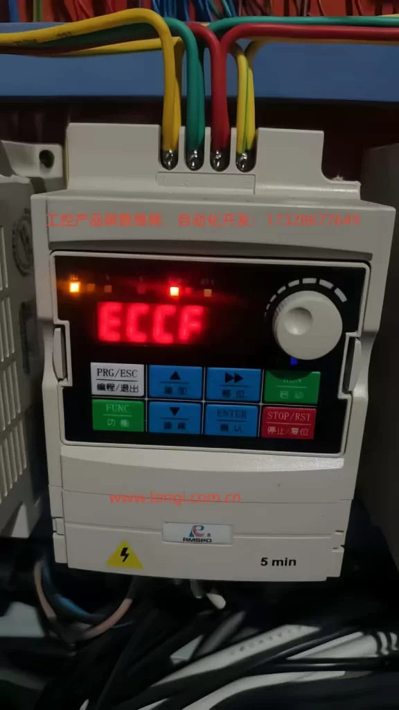
Shanghai Renmin Electric SPD900M Series Inverter ECCF Fault Analysis and Troubleshooting Guide

I. Introduction

In the field of industrial automation, inverters, as the core equipment for motor drives, directly impact production efficiency and equipment lifespan with their stability. The Shanghai Renmin Electric SPD900M series inverters (e.g., SPD990-M0.75KW-H3) are widely used in loads such as fans, pumps, and conveyor belts due to their high cost-effectiveness and reliability. However, users often encounter the ECCF fault (current detection fault) during operation. If not promptly troubleshot, this fault can lead to inverter shutdown or even damage. This article combines the circuit design and field experience of the SPD900M series to provide an in-depth analysis of the causes, troubleshooting steps, and solutions for the ECCF fault, offering users an operable technical guide.

SPD990-M0.75KW-H3

II. Definition and Classification of ECCF Faults

According to the fault code table of the Shanghai Renmin Electric SPD900M series inverters (see Table 1), the ECCF (current detection fault) falls under the “severe fault” category (fault level 16). Once triggered, the inverter immediately stops outputting and requires fault clearance before resetting. The core logic is that the inverter’s CPU detects abnormal current sampling signals or a failure in the auxiliary power supply that prevents the current detection circuit from functioning properly.

Table 1: SPD900M Series ECCF Fault Classification

Fault CodeFault NameSub-Fault TypeFault Description
ECCFCurrent Detection FaultCurrent Sampling Circuit FaultCurrent sampling signal exceeds the normal range (e.g., overcurrent, undercurrent, or signal distortion)
Auxiliary Power Supply FaultAbnormal auxiliary power supply (e.g., 24V/15V) for the current detection circuit, preventing the sampling circuit from functioning

III. In-Depth Cause Analysis of ECCF Faults

The essence of an ECCF fault is the failure of the current detection chain, involving three links: “auxiliary power supply → sampling circuit → CPU processing.” The following is an analysis of specific causes by link:

(I) Current Sampling Circuit Fault: The Core Cause of Signal Anomalies

The SPD900M series adopts a Hall current sensor + operational amplifier solution for current sampling (some low-power models use sampling resistors). The sampled signal is amplified and filtered before being sent to the CPU’s ADC (analog-to-digital converter). Common fault points include:

1. Sampling Resistor/Sensor Damage

The sampling resistor is a key component for current-to-voltage conversion (e.g., the DC bus sampling resistor is typically 10Ω/5W). If its resistance value changes (e.g., increases from 10Ω to 20Ω) or it becomes open-circuit due to overcurrent, overheating, or aging, the sampled voltage will deviate from the normal value (e.g., the normal sampled voltage is 0-5V, but it may drop below 2V after the change). The CPU detects a “mismatch between the sampled voltage and the actual current” and triggers an ECCF.

Case: A user’s SPD990-M1.5KW inverter frequently reported ECCF. Upon disassembly, it was found that the DC bus sampling resistor was burnt black, and its resistance value had become infinite. After replacing it with a resistor of the same specification, the fault disappeared.

2. Operational Amplifier (Op-Amp) Fault

The sampled signal needs to be amplified by an operational amplifier (e.g., LM358 or TL082). If the op-amp’s gain decreases (e.g., the normal gain is 10 times, but it becomes 5 times after a fault) or its output is offset (e.g., an output of 3V with no input) due to power supply fluctuations, electrostatic discharge, or aging, the signal received by the CPU will be incorrect. For example, after the op-amp is damaged, the sampled signal may be misjudged as “overcurrent” even when the motor current is normal.

3. Poor Contact in Sampling Lines

If the connection terminals of the current sensor (e.g., the “+”, “-“, and “OUT” pins of the Hall sensor) become loose due to vibration or oxidation, the sampled signal may be interrupted or fluctuate. Use a multimeter to measure the continuity of the sampling lines. If the resistance is greater than 1Ω, it indicates poor contact.

4. Electromagnetic Interference (EMI)

If the sampling lines do not use shielded wires or are laid parallel to power lines (e.g., motor cables), they may induce high-frequency noise (e.g., harmonics of the PWM wave), causing distortion of the sampled signal (e.g., superimposing杂波 [jitter or noise] of more than 1V). The CPU cannot recognize the distorted signal and misjudges it as a “current detection fault.”

(II) Auxiliary Power Supply Fault: Failure of the “Power Source” for the Sampling Circuit

The current sampling circuit (e.g., Hall sensors and op-amps) relies on an auxiliary power supply (usually DC24V or DC15V) to function. If the auxiliary power supply is abnormal, the sampling circuit will completely stop working, and the CPU will detect “no sampled signal,” triggering an ECCF. Common causes include:

1. Auxiliary Power Supply Module Damage

The auxiliary power supply of the SPD900M series mostly uses a switching power supply module (e.g., TNY264GN). If the module is damaged due to overvoltage, overcurrent, or poor heat dissipation, the output voltage will be 0V or much lower than the rated value (e.g., 24V drops to 10V). Use a multimeter to measure the output terminal of the power supply module. If the voltage is abnormal, the module needs to be replaced.

2. Filter Capacitor Failure

If the filter capacitors (e.g., electrolytic capacitors 470μF/25V) of the auxiliary power supply bulge or leak due to long-term high temperatures or excessive ripple currents, the power supply ripple will increase (e.g., the ripple voltage increases from 50mV to 500mV), interfering with the normal operation of the sampling circuit. In severe cases, a short-circuited capacitor can cause the power supply module to be overloaded and damaged.

Case: A user’s SPD990-M0.75KW inverter reported ECCF. Upon inspection, it was found that the filter capacitor of the auxiliary power supply was bulging. After replacing the capacitor, the power supply ripple dropped to 80mV, and the fault was eliminated.

3. Short Circuit/Open Circuit in Power Lines

If the input lines of the auxiliary power supply (e.g., the lines from the rectifier bridge to the power supply module) are short-circuited due to damaged insulation, the fuse will blow. If the lines are open-circuited (e.g., loose connection terminals), the power supply module will have no input. Check the continuity and insulation resistance of the lines (use a megohmmeter; it should be greater than 10MΩ).

ECCF

IV. Systematic Troubleshooting Steps for ECCF Faults

For ECCF faults, it is necessary to follow the principles of “safety first → from simple to complex → verify by link.” The following is the specific troubleshooting process:

Step 1: Safety Operations (Critical!)

The inverter contains high voltages (the DC bus voltage is approximately 540V, and there is still residual charge even after power-off). Before troubleshooting, the following must be done:

  • Disconnect the input power supply (R/S/T terminals) of the inverter.
  • Wait for more than 5 minutes (to allow the DC bus capacitors to discharge).
  • Use a multimeter to measure the DC bus voltage (P/N terminals) and confirm that it is below 36V (safe voltage).
  • Wear insulating gloves and avoid touching charged components.

Step 2: Check the Auxiliary Power Supply (Quickly Locate “Power Source” Issues)

The auxiliary power supply is the foundation of the sampling circuit. Checking it first can quickly eliminate common faults:

  • Locate the auxiliary power supply module (usually on the left side inside the inverter, marked with “POWER”).
  • Use a multimeter to measure the input voltage of the module (AC220V or DC380V, depending on the model).
  • Measure the output voltage of the module (e.g., DC24V). If the output voltage deviates from the rated value by more than ±10% (e.g., 24V drops below 20V), it indicates a fault in the power supply module or filter capacitor.
  • If the output voltage is normal, continue troubleshooting the sampling circuit.

Step 3: Check the Current Sampling Circuit (Core Link)

If the auxiliary power supply is normal, focus on checking the “signal chain” of the sampling circuit:

1. Check Sampling Resistors/Sensors

  • For sampling resistors: Use a multimeter to measure the resistance value (power must be off). If the resistance value deviates from the nominal value by more than ±5% (e.g., a 10Ω resistor becomes 12Ω), it needs to be replaced.
  • For Hall sensors: Measure the power supply pins of the sensor (e.g., “+” connected to 24V, “-” connected to GND). If the power supply is normal, measure the voltage of the output pin (“OUT”) (normal is 0-5V, corresponding to the motor current of 0-rated value). If the output voltage is 0V or 5V (saturated), it indicates that the sensor is damaged.

2. Check Operational Amplifiers

  • Locate the op-amps in the sampling circuit (e.g., LM358, usually near the sensor).
  • Measure the power supply pins (Vcc/GND) of the op-amp to confirm a normal voltage (e.g., 15V).
  • Measure the voltages of the input pins (IN+/IN-) and output pin (OUT) of the op-amp: If the input pins have a normal sampled signal (e.g., IN+ is 2V and IN- is 1V), but the output pin has no voltage or an abnormal voltage (e.g., OUT is 0V), it indicates that the op-amp is damaged.

3. Check Sampling Lines

  • Use a multimeter to measure the continuity of the sampling lines (e.g., the lines from the sensor to the op-amp). If the resistance is greater than 1Ω, it indicates that the lines are loose or oxidized.
  • Check whether the shielding layer of the lines is grounded (the shielding layer needs to be connected to the GND terminal of the inverter, not the chassis). If it is not grounded, reconnect it.

Step 4: Eliminate Electromagnetic Interference (An Often-Overlooked “Invisible Killer”)

If the sampling circuit hardware is normal but the fault still occurs frequently, consider electromagnetic interference:

  • Check whether the sampling lines are laid parallel to power lines (e.g., motor cables and input power lines). If so, they need to be laid separately (spacing greater than 20cm).
  • Confirm that the shielding layer of the sampling lines is intact (no damage) and reliably grounded (connected to the “GND” terminal of the inverter, not the chassis).
  • Use an oscilloscope to measure the waveform of the sampled signal. If there is obvious jitter (e.g., a peak value exceeding 1V) on the waveform, a magnetic ring (e.g., a nickel-zinc magnetic ring) needs to be connected in series in the sampling lines or a filter capacitor (e.g., a 0.1μF ceramic capacitor) needs to be connected in parallel.

Step 5: Verify Whether the Fault is Eliminated

After completing the above troubleshooting and repairs, a “loaded test” is required:

  • Power on again and press the “STOP/RST” key to reset the fault.
  • Start the motor and observe the display panel of the inverter (whether there is an ECCF alarm).
  • Use a clamp-on ammeter to measure the actual current of the motor and compare it with the “output current” displayed by the inverter (the deviation should be less than ±5%).
  • If the inverter runs for more than 30 minutes without a fault, it indicates that the troubleshooting is successful.

V. Solutions and Cases for ECCF Faults

(I) Solutions for Common Faults

Fault CauseSolution
Sampling resistor damageReplace with a sampling resistor of the same specification (e.g., 10Ω/5W → 10Ω/5W)
Operational amplifier damageReplace with an op-amp of the same model (e.g., LM358 → LM358), and pay attention to the pin definitions (avoid reverse connection)
Auxiliary power supply module damageReplace with a power supply module of the same model (e.g., TNY264GN → TNY264GN), or contact the manufacturer to purchase original parts
Filter capacitor failureReplace with an electrolytic capacitor of the same specification (e.g., 470μF/25V → 470μF/25V, and pay attention to the polarity)
Poor contact in sampling linesRetighten the connection terminals, polish the oxidized layer with sandpaper, or replace with new wires
Electromagnetic interferenceAdd a shielding layer to the sampling lines and ground them, lay them separately from power lines, connect a magnetic ring in series or connect a filter capacitor in parallel

(II) Typical Case Analysis

Case 1: ECCF Caused by a Burnt Sampling Resistor

  • Fault Phenomenon: A SPD990-M1.5KW inverter reported ECCF immediately after startup and could not be reset.
  • Troubleshooting Process:
    • After power-off and discharge, it was found upon disassembly that the DC bus sampling resistor (10Ω/5W) was burnt black, and its resistance value was infinite.
    • Checking the motor cable, it was found that the motor winding was short-circuited (the insulation resistance of the winding measured by a megohmmeter was 0Ω).
    • The motor winding (or motor) was replaced, and the sampling resistor was replaced with one of the same specification.
  • Result: The inverter returned to normal and no longer reported ECCF.

Case 2: ECCF Caused by Filter Capacitor Failure in the Auxiliary Power Supply

  • Fault Phenomenon: A SPD990-M0.75KW inverter frequently reported ECCF, especially in high-temperature environments (summer).
  • Troubleshooting Process:
    • The output voltage of the auxiliary power supply (DC24V) was normal.
    • Using an oscilloscope to measure the power supply ripple, it was found that the ripple voltage was as high as 600mV (normal should be less than 100mV).
    • Upon disassembling the power supply module, it was found that the filter capacitor (470μF/25V) was bulging and leaking.
    • The filter capacitor was replaced with one of the same specification.
  • Result: The power supply ripple dropped to 70mV, the inverter ran stably, and the fault was eliminated.

VI. Preventive Measures for ECCF Faults

To reduce the occurrence of ECCF faults, measures need to be taken from the aspects of “design, use, and maintenance”:

1. Correct Selection and Installation

  • Select an appropriate inverter according to the load type (e.g., select “V/F control” for fans and pumps and “vector control” for precision loads).
  • Use shielded twisted-pair wires for the sampling lines and reliably ground the shielding layer (connect to the GND terminal of the inverter).
  • Lay the power lines separately from the sampling lines (spacing greater than 20cm) and avoid parallel laying.

2. Regular Maintenance

  • Clean the dust inside the inverter every 3 months (use compressed air to blow it away) to avoid dust accumulation leading to poor heat dissipation.
  • Check the connection terminals (e.g., input and output terminals and sampling line terminals) every 6 months and tighten loose screws.
  • Measure the ripple voltage of the auxiliary power supply every year (use an oscilloscope). If the ripple exceeds 100mV, replace the filter capacitor.

3. Reasonable Parameter Settings

  • Correctly set the “current detection threshold” (e.g., set the overcurrent protection threshold to 1.2 times the rated current to avoid false alarms).
  • Avoid long-term overload operation (the motor current should not exceed 1.1 times the rated current).
  • Enable the “current filtering” function (available in some models) to reduce noise in the sampled signal.

4. Manufacturer Service Support

  • If the fault cannot be solved by self-troubleshooting (e.g., CPU board damage or sampling circuit design defects), contact the after-sales service of Shanghai Renmin Electric (phone: 4006720118).
  • The manufacturer can provide remote diagnosis (through the communication interface of the inverter), on-site maintenance, or part replacement services.
  • For models with frequent faults, the manufacturer can upgrade the sampling circuit (e.g., replace with more reliable Hall sensors) to fundamentally solve the problem.

VII. Summary

The ECCF fault is a common fault in the SPD900M series inverters, and its core is the “failure of the current detection chain,” involving multiple links such as the auxiliary power supply, sampling circuit, and electromagnetic interference. During troubleshooting, follow the principles of “safety first and from simple to complex,” first check the auxiliary power supply, then check the sampling circuit, and finally eliminate interference. The solutions should be targeted at specific causes, such as replacing damaged resistors, op-amps, or capacitors, repairing poor line contact, or taking anti-interference measures.

The key to preventing ECCF faults is “regular maintenance + correct use”: regularly clean the dust, check the lines, and measure the power supply ripple; correctly select, install, and set parameters. If a fault that cannot be solved by oneself is encountered, contact the manufacturer in a timely manner to avoid greater losses due to delays.

Through the analysis and guide in this article, it is hoped that users can quickly locate ECCF faults, improve the reliability of inverters, and ensure the continuity of production.

Posted on

CM-SVC Servo Manual User Guide: In-depth Analysis Based on Donghua Machinery Injection Molding Machine Applications

I. Introduction

In the field of plastic injection molding equipment, the application of servo oil pump technology has become a core indicator for measuring the energy efficiency rating and dynamic response performance of injection molding machines. Donghua Machinery Co., Ltd., as a key enterprise in the domestic injection molding machine industry, utilizes the CM-SVC series servo drives as a dedicated product developed specifically for servo oil pump driving. Based on the technical content of the “CM-SVC Servo Drive Operation Guide Manual” and combined with the operational characteristics of Donghua Machinery injection molding machines in actual production, this user guide is compiled to assist field engineers, equipment maintenance personnel, and process debugging personnel in better mastering the entire process of installation, debugging, parameter optimization, and troubleshooting of this servo system.

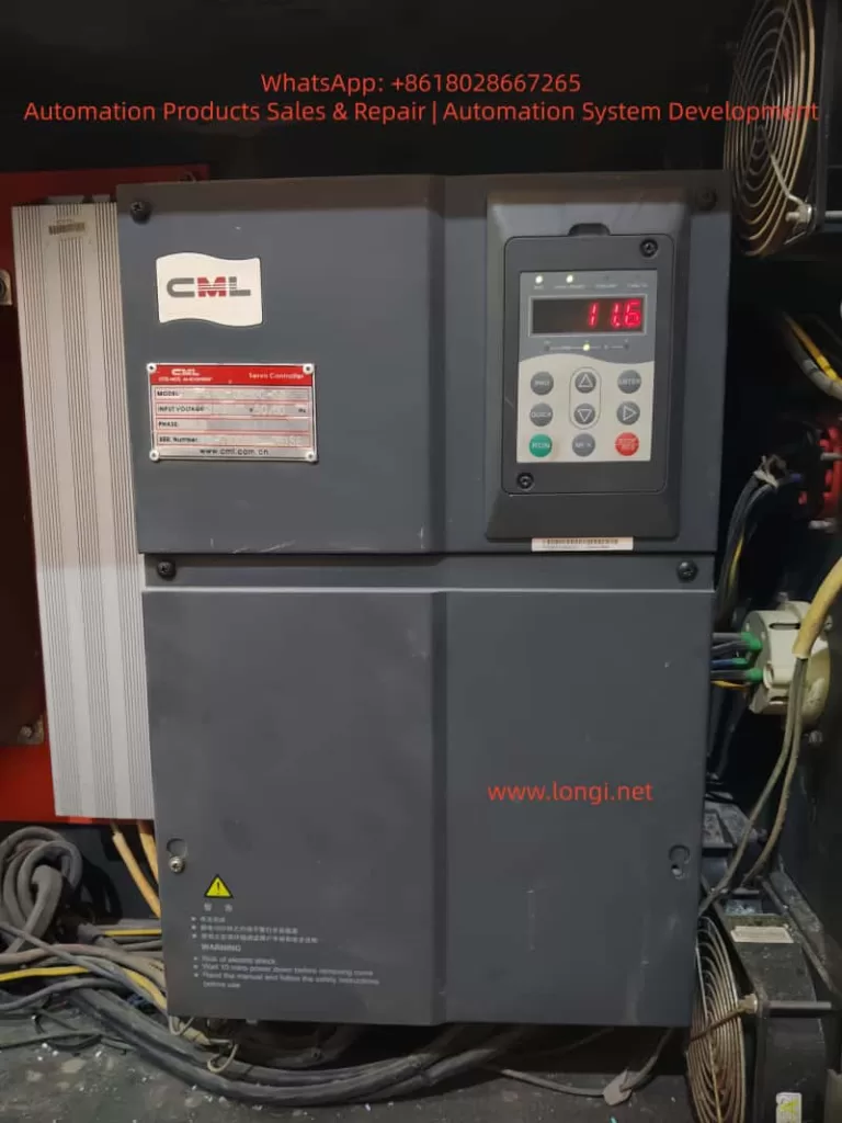
CML drives

II. Technical Positioning of CM-SVC Servo Drive and Its Adaptability to Donghua Machinery

The CM-SVC series servo drives have a rated current coverage ranging from 15A to 300A and are compatible with three-phase 380V power supplies, capable of stable operation within a voltage fluctuation range of -15% to +20%. This series of drives is specifically designed for servo oil pump control scenarios and incorporates a built-in oil pressure closed-loop control algorithm, CAN communication interface, dual analog input channels, and multi-group PID parameter switching functionality, making it highly compatible with Donghua Machinery’s commonly used hydraulic system architecture of quantitative pump + servo motor + pressure sensor.

Donghua Machinery’s injection molding machine product line covers a clamping force range from 80 tons to over 3000 tons, with its hydraulic systems generally adopting a “flow-pressure dual closed-loop” control strategy. Under this system, the CM-SVC drive can operate in two typical oil pressure control modes:

  • Mode 2 (A3-00=2): Analog input method. The AI1 channel receives the oil pressure command (0~10V) from the controller (computer), the AI2 channel receives the flow command (0~10V), and the AI3 channel receives the actual feedback signal from the pressure sensor. This method is suitable for most standard models, offering fast signal response and strong anti-interference capability.
  • Mode 1 (A3-00=1): CAN communication input method. Oil pressure and flow commands are transmitted through the CAN bus, with AI3 still serving as the pressure feedback channel. This method is more suitable for large or high-speed models, reducing attenuation and interference of analog signals during long-distance transmission.

Understanding the differences between these two operating modes is fundamental to correctly using this manual. The following sections will provide detailed explanations centered around actual installation, debugging, and operational maintenance.

III. Key Points for Mechanical Installation and Suggestions for Donghua Electrical Cabinet Layout

3.1 Installation Environment Requirements

According to the content in Chapter 1 and Chapter 3 of the manual, the CM-SVC servo drive must be installed under the following environmental conditions:

  • Ambient temperature: -10°C to +40°C. If the temperature exceeds 40°C but does not exceed 50°C, derating must be applied.
  • Altitude: Below 1000m. Derating is also required if this altitude is exceeded.
  • Relative humidity: Less than 95%, non-condensing.
  • Absence of corrosive gases, flammable gases, oil mist, and conductive dust.

In Donghua Machinery’s actual production workshops, injection molding machines are usually arranged in a centralized manner, and the ambient temperature in summer may approach the upper limit of 40°C. Therefore, the following points should be noted during electrical cabinet design:

  1. Heat Dissipation Space: For drives with power ratings of CM-SVC-00400 and above, when installed vertically, the clear distance A between two sets of drives above and below should be greater than 50mm, and heat-insulating deflectors should be added. For models CM-SVC-00700 and above, A should be greater than 300mm.
  2. Metal Dust Protection: During plastic processing, fine dust may be generated, especially from materials with fillers (such as glass fiber, calcium carbonate). The manual specifically points out that for applications involving metal dust, it is recommended to adopt an external installation method for the radiator. This means extending the heat dissipation part of the drive outside the electrical cabinet while keeping the cabinet sealed.
  3. Vibration Isolation: The manual requires that vibration should not exceed 0.6G and specifically reminds to keep away from punching machines and other equipment. For large injection molding machines, although the impact from the injection unit and clamping unit is not significant, the drive should not be directly installed on the oil tank cover or frame but should be fixed on an independent electrical cabinet backplate welded with reinforcing ribs.

3.2 Lower Cover Removal and Wiring Space

Figure 3-2 in the manual illustrates the removal method of the metal shell lower cover. During actual wiring, it is recommended to first remove the lower cover, complete the main circuit and control circuit wiring, and then reinstall the cover. For models CM-SVC-01400 and above, the main circuit copper bar terminals are relatively large, and sufficient wrench space (recommended not less than 150mm) should be reserved.

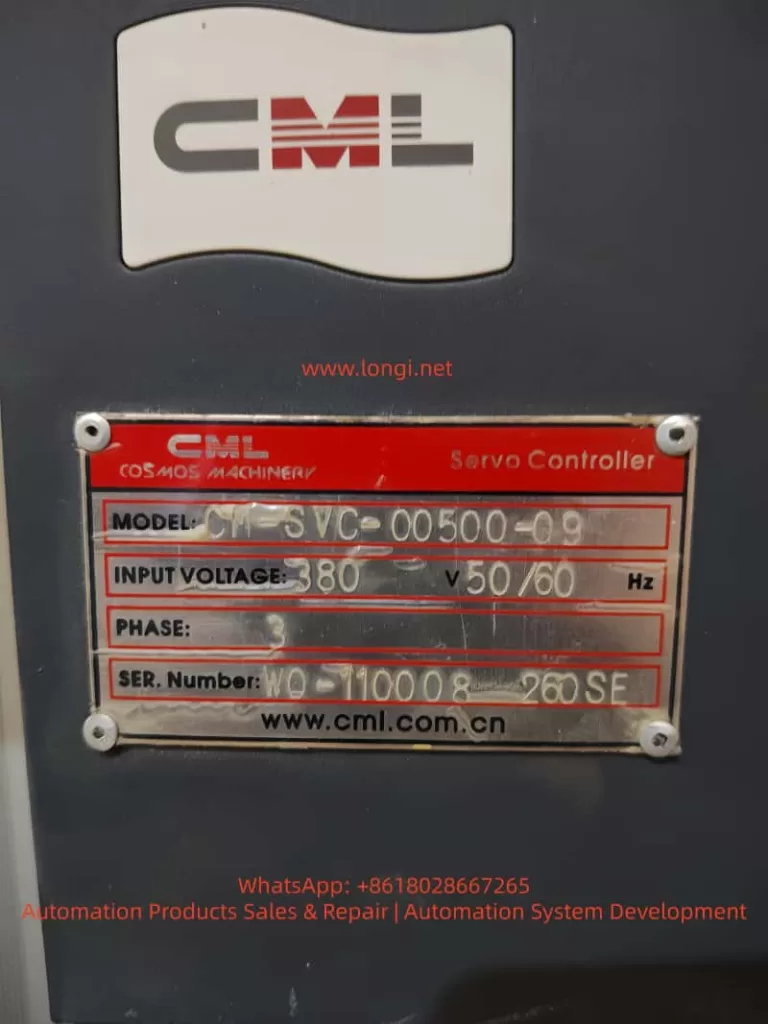
CM-SVC-00500-09

IV. Engineering Guidance for Electrical Wiring

4.1 Key Points for Main Circuit Wiring

Section 3.2.4 of the manual details the terminal definitions of the main circuit and wiring precautions. Combined with Donghua Machinery’s typical configuration, the following key points are emphasized:

  1. Input Power R, S, T: There is no phase sequence requirement, but it must be connected through a circuit breaker and contactor. Table 3-1 in the manual provides recommended values for circuit breakers, contactors, and wire cross-sections for each model. For example, for CM-SVC-00500, a 125A circuit breaker, 100A contactor, 16mm² input wire, and 10mm² output wire are recommended. On-site wiring must not be lower than this standard.
  2. External DC Reactor: For models CM-SVC-01400 and above, an external DC reactor is标配(中文应为“标配”意思是 standard configuration,这里按原文保留英文不译更好,即标配用英文“standard”表达更准确,以下按此处理) standard. During installation, the short-circuit copper bar between P and (+) terminals must be removed, and the reactor must be connected in series between P and (+). This is a common error-prone point. If the copper bar is not removed, the reactor is bypassed, leading to increased input harmonics, reduced power factor, and potentially damaging the rectifier module in severe cases.
  3. Brake Resistor Wiring: For models CM-SVC-00500 and below with built-in brake units, the brake resistor is connected between (+) and PB. The resistance value must not be less than the recommended value in Table 2-6 of the manual; otherwise, the brake unit may be burned. For example, for CM-SVC-00300, the recommended resistance value is ≥32Ω, with a power of ≥1000W. The wiring distance should be less than 5m, and twisted-pair wires should be used.
  4. Output Side U, V, W: It is strictly prohibited to connect capacitors or surge absorbers. When the motor cable length exceeds 100m, an AC output reactor must be added. Donghua Machinery’s large models (such as those above 1300 tons) sometimes place the electrical control cabinet and oil pump motor separately, with distances possibly exceeding 50m. Although not reaching 100m, it is still recommended to evaluate whether to add a reactor based on the actual site conditions to reduce leakage current and motor insulation stress.

4.2 Key Points for Control Circuit Wiring

The control terminals serve as the bridge between the servo drive and the injection molding machine controller (computer). Table 3-3 in the manual provides a detailed description of terminal functions. The following lists the most commonly used wiring schemes:

  • +10V-GND: Provides 10V power externally, with a maximum of 10mA, for connecting external potentiometers (1kΩ~5kΩ). In analog input mode, potentiometers are generally not used; instead, a 0~10V signal is directly output by the controller.
  • AI1-GND: Default pressure setting. In Mode 2, it receives the oil pressure command signal output by the controller.
  • AI2-GND: Default flow setting. In Mode 2, it receives the flow command signal output by the controller.
  • AI3-GND: Pressure sensor feedback signal. Shielded twisted-pair wires must be used, with the shield grounded at the drive side. The sensor is usually of a four-wire system (power +, power -, signal +, signal -), with signal + connected to AI3 and signal – connected to GND.
  • +24V-COM: Provides 24V power externally, with a maximum of 200mA. It is used for dry contact input of DI terminals.
  • DI1-COM: Digital input 1, with the factory default function being forward rotation (FWD), i.e., the oil pump enable signal. Donghua Machinery’s controller usually outputs a passive contact signal connected between DI1 and COM.
  • DI4-COM: Default function is fault reset (RESET), connected to the reset output of the controller.
  • T/A1-T/C1: Relay output, with the default function being fault output. When the drive experiences a fault, this relay operates, providing a switch signal to the controller for shutdown protection.

Section 3.2.5 of the manual also provides solutions when the analog input terminals are interfered with: use shielded cables, keep the wiring distance within 20m, and add filter capacitors and ferrite cores if necessary. At the injection molding machine site, there are many electromagnetic interference sources such as frequency converters, contactors, and relays, making these measures very necessary.

V. Detailed Explanation of Parameter Setting and Debugging Process

5.1 Motor Parameter Tuning (Motor Identification)

This is a prerequisite for the normal operation of the servo system. Chapter 7 of the manual provides detailed tuning steps. At Donghua Machinery’s site, the following sequence should be followed:

  1. Correctly input the motor nameplate parameters: F1-00 (motor type, select 2 for permanent magnet synchronous), F1-01 (rated power), F1-02 (rated voltage), F1-03 (rated current), F1-04 (rated frequency), F1-05 (rated speed).
  2. Set A1-04 (resolver pole pairs), usually 1 pair or 2 pairs, as provided by the motor manufacturer.
  3. Set A3-00=0 (non-oil pressure control mode), F0-02=0 (operation panel control).
  4. If the back EMF (F1-15) is known, perform static tuning (F1-16=1). The motor can be loaded (not disconnected from the oil pump), but it is recommended to open the relief valve to allow the motor to operate under no-load or light-load conditions.
  5. If the back EMF is unknown, dynamic tuning (F1-16=2) must be performed. At this time, the motor must be disconnected from the load (i.e., the motor shaft disconnected from the oil pump); otherwise, the tuning results will be inaccurate, affecting subsequent speed control and pressure stability.

During tuning, if ERR43 (encoder fault) occurs, check the encoder wiring and A1-04 pole pair setting. After successful tuning, parameters such as F1-10 to F1-15 and A1-02 will be automatically filled in.

5.2 Oil Pressure Control Mode Switching and Automatic Parameter Setting

When switching from non-oil pressure mode (A3-00=0) to oil pressure mode (A3-00=1 or 2), the parameters listed in Table 7-4 of the manual will be automatically set. This means that users do not need to manually modify parameters such as F0-01 (control mode), F0-02 (command source), F4-00~F4-04 (terminal functions), as the system will automatically configure them to recommended values.

However, it should be noted: after automatic setting, if the user manually modifies these parameters again and wishes to retain them, their rationality must be confirmed. For example, F0-17 (acceleration time 1) and F0-18 (deceleration time 1) will be set to 0.0s. This is because in oil pressure control mode, acceleration and deceleration are actually determined by the oil pressure PID and flow command, rather than traditional acceleration and deceleration times. If users do not understand this, they may mistakenly believe that the parameters are lost.

5.3 Core Process Parameter Setting

The following parameters directly affect the action quality of the injection molding machine and need to be adjusted based on the actual mold and process:

  • A3-01 (maximum speed): Corresponds to the motor speed when the flow command is 100%. It is recommended to be set within 140% of the motor’s rated speed. For example, if the rated speed is 1500rpm, the maximum speed can be set to 2100rpm. After exceeding 150% of the rated speed, the motor torque decreases sharply, which is unfavorable for pressure holding.
  • A3-02 (system oil pressure): The highest working pressure set for the injection molding machine, in kgf/cm². For example, 175kgf/cm² (approximately 17.2MPa).
  • A3-03 (maximum oil pressure): The range of the pressure sensor, which should be consistent with the sensor’s nominal value. For example, if the sensor range is 250kgf/cm² (corresponding to 0~10V output), then A3-03=250.0.
  • A3-04 (oil pressure command rise time): Filters the oil pressure command signal, in ms. A smaller value results in faster response, but too small a value may cause pressure overshoot. It is generally set to 20~50ms.
  • A3-05~A3-07 (first group of PID): Proportional gain Kp, integral time Ti, and derivative time Td. This is the most commonly used set of PID parameters. Increasing Kp or decreasing Ti can improve response speed, but excessive values may cause oscillation. Donghua Machinery’s typical value range: Kp=150~300, Ti=0.05~0.20s, Td is generally set to 0 or a very small value.
  • A3-08 (maximum reverse speed): The maximum reverse speed during pressure relief, in percentage of the maximum speed. For example, if set to 50%, the reverse speed does not exceed half of the maximum speed. Reverse rotation is used for rapid pressure relief, but excessive values may cause oil pump reverse rotation noise and even damage the oil pump.
  • A3-09 (bottom flow): Minimum flow setting, as a percentage of the maximum speed. It is used to overcome internal leakage of the oil pump and prevent air from entering the oil circuit. It is generally set to 0.5%~3%.
  • A3-10 (bottom pressure): Minimum pressure setting, in kgf/cm². It is also used to maintain positive pressure in the oil circuit and is generally set to 0.5~2.0kgf/cm².

5.4 Multi-group PID Switching Logic

The manual provides four groups of oil pressure PID parameters, which can be switched through the digital state combination of DI2 and DI3. Table 7-2 shows the combination relationship. During the actual injection molding process, different DI combinations can be output by the controller to switch PID groups based on different requirements for pressure response in different actions (such as rapid injection, pressure holding, plasticizing, and cooling). For example:

  • Rapid injection stage: Fast response is required, so the first group with larger Kp and smaller Ti can be selected.
  • Pressure holding stage: Good stability and no overshoot are required, so the second or third group with moderate Kp and larger Ti can be selected.

This function requires the controller to support multiple DO outputs and to perform segmented PID scheduling in the program.

5.5 AI Zero-drift Automatic Calibration

Zero-drift inevitably exists in pressure sensor and controller-output analog signals. The manual provides a very practical function: set A3-20 to 1, and the drive will automatically detect the zero-drift values of AI1, AI2, and AI3 and write them to F4-18, F4-23, and F4-28 (minimum input values). When performing this function, ensure that all analog input signals are 0 (i.e., no pressure command, no flow command, and the pressure sensor is at zero pressure). After calibration, A3-20 automatically reverts to 0.

VI. Fault Diagnosis and Rapid Handling

Chapter 9 of the manual lists 23 fault codes and corresponding handling countermeasures. The following are the most common types of faults and handling experiences at Donghua Machinery’s site:

  1. ERR02~ERR04 (overcurrent): Common during acceleration, deceleration, or constant speed processes. First, check whether the motor parameters are accurate, especially F1-03 rated current and F1-15 back EMF. Second, check whether the acceleration and deceleration times are too short. For oil pressure control mode, check whether the A3-05~A3-07 PID parameters are too large, causing oscillation.
  2. ERR05~ERR07 (overvoltage): Common during deceleration or pressure relief processes. The reason is that the motor’s regenerative energy cannot be consumed by the brake resistor. Check whether the resistance value and power of the brake resistor comply with Table 2-6, and whether the brake unit is working properly. For large inertia systems (such as large injection molding machines), it may be necessary to increase the brake resistor power or use multiple brake units in parallel.
  3. ERR12 (input phase loss): Only models CM-SVC-00350 and above have this protection. Check whether the input power R, S, T is phase-missing and whether the circuit breaker and contactor contacts are in good condition.
  4. ERR13 (output phase loss): Check whether the connection from the drive output U, V, W to the motor is disconnected or has poor contact.
  5. ERR14 (module overheating): Check whether the fan is running, whether the air duct is blocked, whether the carrier frequency F0-15 is set too high (recommended 4~8kHz), and whether the ambient temperature is too high.
  6. ERR42 (CAN communication fault): Occurs under Mode 1 or Mode 3. Check the CAN bus wiring (CANH, CANL) for open circuit or short circuit, whether the terminal resistance matches (120Ω), and whether the communication address A2-01 and baud rate A2-00 are consistent with the controller.
  7. ERR43 (encoder fault): Occurs during tuning or operation. Check the encoder (resolver) wiring, confirm the A1-04 pole pairs, and check whether the PG card is properly inserted.
  8. ERR44 (excessive speed deviation): The deviation between the actual motor speed and the command speed exceeds the F9-14 set value and lasts longer than F9-15. Common causes include motor blockage, encoder fault, inaccurate motor parameters, and too low torque upper limit F2-10 setting.

VII. Daily Maintenance and Replacement of Vulnerable Parts

Section 2.7 of the manual provides detailed requirements for maintenance and upkeep. For Donghua Machinery users, the following regular maintenance plan is recommended:

  • Daily inspection: Check whether the motor operation sound is abnormal, whether the vibration increases, whether the cooling fan runs normally, and whether the current and voltage displayed on the drive panel are within the normal range.
  • Quarterly cleaning: Use a vacuum cleaner or compressed air (dry, low pressure) to clean the dust accumulated on the drive air inlet, heat sink, and fan. For workshops with high dust levels, this should be shortened to once a month.
  • Fan replacement every two years: The manual indicates that the fan life is 2~3 years. When the fan makes abnormal noise or the speed decreases, it should be replaced immediately.
  • Electrolytic capacitor inspection every four years: The life is 4~5 years. Check for electrolyte leakage and whether the safety valve is raised. If necessary, measure the electrostatic capacitance and insulation resistance.
  • Long-term storage: If the drive is stored for more than 2 years, it must be powered on once. The power-on time should be at least 5 hours, and the voltage should be slowly increased to the rated value using a voltage regulator to restore the performance of the electrolytic capacitors.

VIII. Summary

The CM-SVC servo drive is a powerful drive product dedicated to servo oil pump control for injection molding machines. This article provides an engineering interpretation of the key content in the manual, combining the actual application scenarios of Donghua Machinery injection molding machines, from mechanical installation, electrical wiring, parameter debugging, fault handling, to daily maintenance.

The key to mastering this user guide lies in understanding three aspects: first, motor parameter tuning is the foundation and must be accurately performed; second, oil pressure PID adjustment is the soul and needs to be optimized in segments based on the process actions; third, fault codes are clues and should be judged in combination with the manual flowchart and actual measurement data on site.

It is hoped that this article can help field engineers reduce debugging time, lower fault rates, extend equipment life, and enable the CM-SVC servo drive to deliver optimal performance on Donghua Machinery’s injection molding machines.

Posted on

In-depth Analysis and Solution Guide for U-phase Current Transformer Zero Offset (CT1) Fault in Lingshida LSD-B7000 Series Inverters

I. Introduction

In industrial automation production lines, inverters serve as the core equipment for motor driving, and the accuracy of their current sampling systems directly determines the stability of motor control. The Lingshida LSD-B7000 series inverters, known for their high cost-effectiveness and reliable vector control performance, are widely applied in load scenarios such as fans, pumps, conveyor belts, and injection molding machines. However, during long-term operation, the U-phase current transformer zero offset (Fault Code 18, displaying “C”, “T”, “1”) is one of the high-frequency faults in this series of inverters. This fault can lead to abnormal current sampling values, triggering overcurrent protection shutdowns, and even causing motor damage due to misjudgment of current, seriously affecting production efficiency.

This article combines the hardware architecture, control principles, and on-site maintenance experience of the LSD-B7000 series to systematically analyze solutions for the CT1 fault from four dimensions: the nature of the fault, diagnostic procedures, solution strategies, and case studies, providing maintenance personnel with a practical technical guide.

II. The Nature and Causes of CT1 Faults

1. The Role of Current Transformers (CTs) and the Definition of Zero Offset

Current transformers are key components for current sampling in inverters. Their core function is to convert the large current in the motor windings (primary side, e.g., 0-100A) into a small current (secondary side, e.g., 0-5A) or voltage signal (e.g., 0-10V) at a fixed ratio for the main control chip (DSP/MCU) to calculate motor current, torque, and power.

Zero offset refers to the phenomenon where the secondary side output is not zero when there is no current on the primary side. For the LSD-B7000 series, a zero offset in the U-phase CT (CT1) can cause the control circuit to misjudge the motor current. When the sampled value exceeds the threshold (usually 5%-10% of the rated current), it triggers the “CT1” fault (Code 18), forcing a shutdown.

2. Main Causes of Zero Offset

The root causes of CT1 faults can be classified into three categories: hardware defects, software misconfigurations, and external interference, as detailed below:

Hardware Defects:

  • CT Damage: Residual magnetism in the iron core (due to long-term energization without demagnetization), winding short circuits/open circuits (due to worn insulation or overloading), or incorrect ratio (due to selecting the wrong model during replacement).
  • Wiring Issues: Loose primary/secondary side connections, oxidation (increasing contact resistance), or incorrect phase sequence (U/V/W reversed).
  • Sampling Circuit Faults: Operational amplifier offset (e.g., OP07 with an offset voltage exceeding 75μV), changes in sampling resistor values (e.g., a 0.1Ω resistor increasing to 0.15Ω), or leakage in filter capacitors (causing signal drift).

Software Misconfigurations:

  • Incorrect current ratio parameters (e.g., CT ratio of 100/5, but Pr012 set to 10 instead of 20).
  • Unupdated zero offset calibration parameters (due to long-term operation, CT characteristics change, requiring recalibration).
  • Improper settings for the fault auto-reset parameter (Pr137) (although CT1 belongs to codes 14-30 and cannot be auto-reset, misconfiguration may mask the fault).

External Interference:

  • Power supply fluctuations (three-phase voltage imbalance exceeding 5%).
  • Electromagnetic interference (power and signal lines not separated, shielding not grounded).
  • Load abnormalities (motor stalling or overloading causing CT iron core saturation).

III. Precise Diagnostic Procedures for CT1 Faults

The digital operator (LSD-B) of the LSD-B7000 series provides comprehensive fault diagnosis functions. Combined with hardware testing tools (multimeter, oscilloscope, megohmmeter), faults can be located using the following steps:

Step 1: Confirm Fault Code and Display Content

Operation: Press the DSPL key on the operator to switch to the fault display mode and observe the screen:

  • If “C”, “T”, “1” flash alternately or Code “18” is displayed directly, the CT1 fault is confirmed.
  • If other codes are displayed (e.g., “O”, “H”, “2” for overheating faults), chain faults must be excluded first.
    Note: Fault codes are latching and must be reset by pressing the STOP/RESET key before they can be cleared. Before resetting, record the operating status at the time of the fault (e.g., frequency, current, load).

Step 2: Hardware Wiring and CT Inspection

(1) Wiring Inspection

Safety Operation: Disconnect the inverter’s input power (R/S/T), wait 5 minutes (for the DC bus capacitors to discharge), and use a multimeter to measure the DC bus voltage (between P/N) to ensure it is 0V before opening the housing.
Inspection Content:

  • CT1 Primary Side (connected to motor U-phase) wiring: Check for loose terminals, broken wires, or damaged insulation.
  • CT1 Secondary Side (connected to the sampling circuit) wiring: Check for confusion with V/W phase wiring (incorrect phase sequence causes zero offset) and oxidation of terminals (polish with sandpaper and re-crimp).
  • Grounding Check: Ensure the CT housing is reliably connected to the inverter’s grounding terminal (PE) (grounding resistance must be less than 4Ω).

(2) CT Inspection

Resistance Measurement: Use a multimeter to measure the primary side resistance (normal range: 0.1-0.5Ω, e.g., about 0.2Ω for a 100/5 CT) and the secondary side resistance (normal range: 5-20Ω, e.g., about 10Ω for a 100/5 CT). If the resistance is ∞ (open circuit) or 0Ω (short circuit), the CT is damaged.
Insulation Measurement: Use a megohmmeter (500V) to measure the insulation resistance between the primary and secondary sides, between the primary side and housing, and between the secondary side and housing (normal should be greater than 10MΩ). If the insulation resistance is less than 1MΩ, the CT insulation has failed.
Residual Magnetism Detection: Use an oscilloscope to measure the CT secondary side output (with no current). If a continuous induced voltage (e.g., above 0.1V) is present, the iron core has residual magnetism and requires demagnetization using a demagnetizer.

Step 3: Sampling Circuit Inspection

The current sampling circuit of the LSD-B7000 series is usually located near the main control board, marked as “CT1”, “U-phase Sampling”, or “Current Detection”. The inspection steps are as follows:

Locate the Circuit

Find the CT1 secondary side connection terminals and follow the wires to locate the sampling resistor (usually a 0.1Ω/5W metal film resistor) and operational amplifier (e.g., OP07, LM358).

Signal Measurement

  • No-load Condition (motor stopped): Use an oscilloscope to measure the voltage across the sampling resistor (normal should be close to 0V). If the voltage exceeds 0.05V, a zero offset is present.
  • Measure the input voltage of the operational amplifier (non-inverting and inverting terminals): normal should be close to 0V. If the input voltage is abnormal, check the feedback resistor (e.g., Rf = 10kΩ) for value changes (measure resistance with a multimeter, replace if the error exceeds ±1%).
  • Measure the output voltage of the operational amplifier: normal should be close to 0V. If the output voltage is continuously high (e.g., above 1V), the operational amplifier is offset and requires replacement (the typical offset voltage of OP07 is 10μV, with a maximum of 75μV).

Component Inspection

  • Sampling Resistor: If the resistance value changes (e.g., from 0.1Ω to 0.12Ω), it will increase the sampling voltage and requires replacement with a resistor of the same specification.
  • Filter Capacitor: If the capacitor leaks (measure capacitance with a capacitor meter or insulation resistance with a multimeter), it will cause signal drift and requires replacement (e.g., a 10μF/25V electrolytic capacitor).

Step 4: Software Parameter and External Factor Inspection

Parameter Inspection

  • Enter the parameter mode (press the PROG key), select Pr012 (current transformer ratio), and confirm it matches the CT nameplate (e.g., for a CT of 150/5, Pr012 should be set to 30).
  • Select Pr050 (U-phase zero offset calibration) and check the current value (normal should be 0.00A or 0.00V). If the value is abnormal (e.g., 0.1A), recalibration is required.
  • Check Pr137 (fault auto-reset count): although CT1 belongs to codes 14-30 and cannot be auto-reset, confirm it is not misconfigured to “0” (no auto-reset for any faults).

External Factor Inspection

  • Power Supply Inspection: Use an oscilloscope to measure the input power waveform (three-phase 380V). If there are phase losses or harmonics (waveform distortion rate exceeding 10%), install an input filter.
  • Load Inspection: Use a clamp-on ammeter to measure the actual motor current and compare it with the inverter’s displayed current (error should be less than 5%). If the actual current is normal but the inverter’s display is abnormal, the sampling circuit is faulty.
  • Interference Inspection: Check if signal lines are shielded (shielding must be grounded at one end), the distance between power and signal lines is greater than 20cm, and the inverter is installed in a well-ventilated environment (temperature below 40°C).

IV. Targeted Solution Strategies for CT1 Faults

1. Hardware Fault Repair

Wiring Issues: Re-crimp loose terminals (use a torque screwdriver to tighten to 0.5N·m), polish oxidized contacts (with sandpaper), and replace damaged wires (use copper wires of the same specification with a cross-sectional area not less than the original).
CT Damage: Replace with a CT of the same model and ratio (note the installation direction: primary side connected to the motor, secondary side connected to the sampling circuit). Ensure the CT is installed more than 5cm away from the motor connection terminals to avoid vibration-induced insulation wear.
Sampling Circuit Faults:

  • Operational Amplifier Offset: Replace with the same model operational amplifier (e.g., replace OP07 with OP07D for lower offset).
  • Resistor Value Change: Replace with a metal film resistor (precision ±1%, power rating not less than the original).
  • Capacitor Leakage: Replace with an electrolytic capacitor (voltage rating not lower than the original, capacitance consistent).

2. Software Parameter Adjustment

Zero Offset Calibration:

  • Step 1: Ensure the motor is stopped (no load) and press the PROG key to enter the parameter mode.
  • Step 2: Use the up/down keys to select Pr050 (U-phase zero offset) and press the ENTER key to enter calibration mode.
  • Step 3: The screen displays the current zero offset value (e.g., 0.05A). Use the up/down keys to adjust it to 0.00A.
  • Step 4: Press the ENTER key to save and exit calibration mode (press the STOP/RESET key to return to operation mode).

Parameter Restoration: If parameters are混乱 (e.g., Pr012 set incorrectly), press PROG+DSPL keys to restore factory settings (note to back up important parameters such as motor rated power and pole pairs) and reconfigure motor parameters (Pr001-Pr005) and current parameters (Pr012).

3. External Environment Improvement

Grounding Optimization: Connect the inverter’s grounding terminal to the factory grounding busbar (grounding resistance less than 4Ω) and ground the motor housing separately (avoid common grounding interference).
Interference Suppression:

  • Power Side: Install an EMI filter (e.g., Schaffner FN2010) to suppress harmonics.
  • Output Side: Install a dv/dt filter (e.g., Siemens SINOFILTER) to reduce electromagnetic interference on the motor side.
  • Signal Lines: Use shielded twisted-pair cables (shielding connected to the inverter end) and separate them from power lines (distance greater than 20cm).
    Load Adjustment: If the motor is overloaded (actual current exceeds 1.2 times the rated current), reduce the load or replace with a higher-power motor. If stalling occurs, check the mechanical parts (e.g., bearings, conveyor belts) for jamming.

V. Typical Case Studies

Case 1: CT1 Fault Caused by Wiring Oxidation

Fault Phenomenon: An LSD-B7000-15kW inverter used for a fan suddenly stopped during operation, displaying a CT1 fault (Code 18).
Diagnostic Process:

  • After resetting, the inverter restarted but faulted again after 10 minutes.
  • Opened the housing and inspected the CT1 secondary side connection terminals, finding a black oxide film on the copper pieces with a contact resistance of 0.3Ω (normal should be less than 0.1Ω).
  • Polished the oxide film with sandpaper and re-crimped the terminals (torque 0.5N·m), reducing the contact resistance to 0.05Ω.
  • Tested operation for 24 hours, and the fault did not reoccur.
    Cause: Long-term operation in a humid environment (85%) caused oxidation of the connection terminals, leading to poor contact and signal drift on the secondary side, triggering the zero offset fault.

Case 2: Zero Offset Fault Caused by CT Residual Magnetism

Fault Phenomenon: An LSD-B7000-22kW inverter used for a water pump frequently displayed CT1 faults and could operate briefly after resetting.
Diagnostic Process:

  • Checked CT1 resistance: primary side 0.2Ω (normal), secondary side 10Ω (normal).
  • Insulation resistance: 15MΩ between primary and secondary sides (normal).
  • With no load, used an oscilloscope to measure the CT1 secondary side output: a continuous voltage of 0.2V (normal should be close to 0V), indicating residual magnetism in the iron core.
  • Demagnetized the CT iron core using a demagnetizer (operation: bring the demagnetizer close to the iron core and slowly move it away, repeating 3 times).
  • Recalibrated the zero offset (Pr050 = 0.00A), and test operation was normal.
    Cause: Frequent starting and stopping of the water pump motor (20 times per day) prevented complete demagnetization of the CT iron core, causing a residual magnetism-induced voltage on the secondary side and triggering the zero offset fault.

Case 3: Fault Caused by Sampling Resistor Value Change

Fault Phenomenon: An LSD-B7000-7.5kW inverter used for a conveyor belt displayed a CT1 fault, but the actual motor current (measured with a clamp-on ammeter) was 10A (rated current 15A), while the inverter displayed 12A.
Diagnostic Process:

  • Checked CT1: resistance and insulation were normal.
  • Inspected the sampling circuit: the sampling resistor (0.1Ω) actually measured 0.15Ω (a 50% increase).
  • Replaced the sampling resistor with a 0.1Ω/5W metal film resistor, reducing the sampling voltage from 0.15V to 0.1V (corresponding to 10A).
  • Recalibrated the zero offset (Pr050 = 0.00A), and test operation was normal.
    Cause: The sampling resistor, subjected to long-term high current (10A), heated up and increased in resistance, raising the sampling voltage and triggering the zero offset fault.

VI. Preventive Measures and Maintenance Recommendations

1. Regular Maintenance Plan

  • Monthly: Check for loose or oxidized connection terminals and clean inverter dust (use compressed air for blowing).
  • Every 3 months: Measure CT resistance and insulation resistance, and calibrate zero offset parameters (Pr050-Pr052).
  • Every 6 months: Inspect operational amplifiers, resistors, and capacitors in the sampling circuit and replace aging components.
  • Annually: Demagnetize the CT using a demagnetizer and check grounding resistance (less than 4Ω).

2. Environment Optimization

  • Installation Environment: Install the inverter in a well-ventilated, dry location (temperature 0-40°C, relative humidity less than 80%) and avoid direct sunlight.
  • Heat Dissipation Improvement: Install a cooling fan (e.g., an axial fan on top of the inverter) to ensure unobstructed heat dissipation channels.
  • Interference Protection: Separate power and signal lines, use shielded cables, and install filters.

3. Parameter Management

  • Establish Parameter Backups: Regularly back up inverter parameters using the operator or a computer (via RS485 interface) to avoid loss due to misoperation.
  • Record Parameter Modifications: When modifying parameters, record the modification time, parameter number, and before/after values for traceability.
  • Fault Recording: View the historical fault record (press the DSPL key to switch to fault record mode), analyze fault frequency, and take preventive measures in advance.

VII. Conclusion

The CT1 fault (U-phase current transformer zero offset) in Lingshida LSD-B7000 series inverters is the result of a combination of hardware defects, software misconfigurations, and external interference. However, through precise diagnosis (using fault codes and hardware testing), targeted repairs (wiring/CT/sampling circuit), software calibration (zero offset parameters), and environmental improvements (grounding/interference), this fault can be effectively resolved.

Maintenance personnel need to master the working principles of current transformers, sampling circuit testing methods, and parameter adjustment procedures, while also emphasizing preventive maintenance (regular inspection of wiring, calibration of parameters, and environmental improvement) to reduce the fault occurrence rate. For high-frequency faults (e.g., wiring oxidation, CT residual magnetism), the stability of the inverter can be further enhanced by replacing high-reliability components (e.g., silver-plated connection terminals, permalloy iron core CTs) and adding demagnetization circuits.

With the development of Industry 4.0, intelligent inverters (e.g., LSD-B8000 series) already have self-calibration functions (automatic compensation for zero offset), but traditional LSD-B7000 series still require manual maintenance. The diagnostic and solution methods in this article are not only applicable to the LSD-B7000 series but can also serve as a reference for current sampling faults in other brands of inverters.

Posted on

SES800 Servo Drive Er.SC1 Fault: In-Depth Analysis and Resolution Guide

I. Introduction

In the field of industrial automation, servo drives serve as the core hub connecting controllers (PLCs, upper computers) and actuating motors. Their communication stability directly determines the continuous operation capability of production lines. The SES800 series servo drives, renowned for their high cost-effectiveness and precise motion control performance, are widely applied in scenarios such as machine tools, packaging machinery, textile equipment, and logistics conveyor lines. However, during long-term operation, the Er.SC1 serial port communication anomaly is one of the most frequently reported faults by users. This can range from causing equipment shutdown to triggering production accidents. This article provides a comprehensive breakdown of the Er.SC1 fault, covering its definition, root causes, resolution process, case studies, and preventive measures, offering engineers a practical troubleshooting guide.

II. The Essence of the Er.SC1 Fault: Serial Communication Link Interruption

1. Fault Code Definition

Er.SC1 is the serial port communication anomaly fault code for SES800 drives (“SC” stands for “Serial Communication”). According to the drive manual, this fault is triggered when the following situations occur:

  • The serial communication link between the drive and external devices (PLCs, upper computers, HMIs) is interrupted.
  • Communication data frame errors occur (e.g., checksum failures, baud rate mismatches).
  • Communication anomalies are detected when fault alarm parameters are enabled.
    At this point, the drive stops motor output, and the operation panel displays “Er.SC1.” The fault can only be cleared by pressing the STOP/RESET key or resolving the underlying issue to resume operation.

2. The Role of Serial Communication Systems

The serial port of the SES800 (typically an RS485 interface, with some models supporting RS232) acts as the “nerve center” for interaction with external systems, performing the following functions:

  • Instruction Transmission: Receiving control instructions from PLCs/upper computers (e.g., start, stop, speed setting, torque limiting).
  • Status Feedback: Sending drive status information to external devices (e.g., current, voltage, rotational speed, fault codes).
  • Parameter Configuration: Modifying drive parameters via the communication interface (e.g., PID gains, acceleration/deceleration times).
  • Diagnostic Debugging: Using dedicated software (e.g., SES Studio) to read fault records and monitor real-time waveforms.
    Once the communication link is interrupted, the drive cannot receive instructions or provide feedback, causing the system to enter “safe shutdown” mode and triggering Er.SC1.
SES800-4T45

III. The Four Core Causes of the Er.SC1 Fault

Based on the SES800 manual and field troubleshooting experience, the root causes of Er.SC1 can be summarized into four categories, ranked by frequency of occurrence:

1. Baud Rate/Communication Parameter Mismatch (40%)

The baud rate serves as the “speed benchmark” for serial communication. If the baud rates of the drive and external device are inconsistent, data frame synchronization errors occur—where a “1” sent by the transmitter may be misinterpreted as a “0” by the receiver, ultimately leading to communication failures.

Key Parameters:

  • P15.03: Communication baud rate selection (default value for SES800-4T45 is 9600 bps).
  • P97.00: Fault alarm enable (bit0 = serial port communication fault alarm, 1 = enabled, 0 = disabled).
  • External device parameters: Baud rate, data bits (typically 8), stop bits (typically 1), and parity bits (typically none/even parity) for PLCs/upper computers.

Case Study: A machine tool factory’s SES800 drive connected to a Siemens S7-200 PLC triggered Er.SC1 because the PLC’s baud rate was set to 115200 bps, while the drive’s P15.03 remained at the default 9600 bps. As a result, the PLC’s instructions could not be interpreted by the drive, causing the fault.

2. Serial Communication Line Faults (30%)

Line issues are among the most common “hidden faults” in industrial settings, including:

  • Loose/Oxidized Connections: Unsecured terminal block screws or oxidized interface pins (especially for outdoor equipment).
  • Line Damage/Short Circuits: Cables squeezed by machinery, gnawed by rodents, or with damaged shielding leading to signal interference.
  • Missing Terminal Resistors: RS485 buses require 120Ω terminal resistors connected in parallel at both ends (some models have built-in resistors, while others require external ones). Failure to do so can cause signal reflections.
  • Electromagnetic Interference (EMI): Communication lines running parallel to inverter or motor power lines, resulting in crosstalk.

Case Study: A packaging machinery factory’s SES800 drive used ordinary twisted-pair cables (unshielded) for communication, running parallel to inverter power lines. Field testing revealed that the RS485 signal was superimposed with high-frequency noise (amplitude up to 3V), causing data frame checksum errors and triggering Er.SC1.

3. Upper Computer/External Device Faults (20%)

If the upper computer (industrial PC, HMI) or PLC is not functioning properly, the drive cannot establish a communication link, also triggering Er.SC1. Common scenarios include:

  • The upper computer software is not launched/has crashed (e.g., operator accidentally closed the software).
  • Mismatched communication protocols between the upper computer and drive (e.g., drive uses Modbus RTU, while upper computer uses Modbus ASCII).
  • Incorrect IP address/port settings for the upper computer (for network-based communication).
  • PLC program logic errors (e.g., failure to send a “communication enable” instruction).

Case Study: A logistics conveyor line’s SES800 drive triggered Er.SC1 because the upper computer (industrial PC) automatically restarted during a system update, failing to launch the communication software. Restarting the software resolved the fault.

4. Drive Communication Module Damage (10%)

If the above causes are ruled out, consider hardware faults in the drive’s communication module:

  • Burnt RS485 chips (e.g., MAX485) due to overvoltage or electrostatic discharge.
  • Oxidized/bent pins at the serial port interface (caused by frequent plugging/unplugging).
  • Damaged capacitors/resistors in the communication circuit (e.g., failed filtering capacitors).
ER.SC1

IV. Step-by-Step Resolution Guide for the Er.SC1 Fault

The following is a standardized troubleshooting process (ranked by priority) to help engineers quickly locate the issue:

Step 1: Confirm Fault Phenomena and Context

  • Check the operation panel: Does it display “Er.SC1”? Are there any accompanying faults (e.g., overcurrent, overvoltage)?
  • Inquire with operators: Were any parameters modified before the fault occurred? Was the communication line replaced? Did the upper computer exhibit any anomalies?
  • Check equipment status: Is the motor shut down? Does the upper computer display a “communication interruption” message?

Step 2: Investigate Upper Computer/External Device Status

Objective: Confirm whether the external device is functioning properly and sending instructions to the drive.

  • Check the upper computer: Is the software launched? Does it indicate “communication normal”?
  • Check the PLC: Is the program running? Are there any “communication fault” alarms?
  • Test instruction transmission: Use the upper computer to send a “jog” instruction and observe whether the drive responds (e.g., panel displays “RUN”).

Case Study: A textile factory’s SES800 drive triggered Er.SC1 due to a virus-induced crash of the upper computer software, which went unnoticed by the operator. Restarting the software resolved the fault.

Step 3: Inspect Communication Lines

Objective: Confirm whether the lines are connected and free from interference.

Power-Off Inspection:

  • Unplug the communication line and use a multimeter to measure the A-B resistance at the drive end (normal value should be 120Ω if terminal resistors are present).
  • Check terminal blocks for loose connections or oxidized pins. Clean and retighten them with alcohol wipes.
  • Inspect the line for damage or exposed shielding (ensure the drive end is grounded).

Power-On Inspection:

  • Use a multimeter to measure the RS485 signal voltage (A-B differential voltage should be 2–5V).
  • Use an oscilloscope to measure the signal waveform (normal waveform is an inverted square wave with consistent amplitude and no noise).
  • Replace the line with a spare shielded twisted-pair cable and observe whether the fault disappears.

Case Study: A machine tool factory’s SES800 drive had loose terminal block connections due to vibration. Tightening the terminals resolved the Er.SC1 fault.

Step 4: Verify Baud Rate/Communication Parameters

Objective: Ensure parameter consistency between the drive and external device.

  • Check drive parameters:
    • Press the “MENU” key to enter parameter mode and locate “P15.03” (baud rate).
    • Record the current value (e.g., 9600) and compare it with the external device’s baud rate (e.g., PLC’s 115200).
  • Modify parameters:
    • Use the up/down keys to select the correct baud rate (e.g., 115200 corresponds to P15.03 = 4).
    • Press “ENTER” to confirm and “MENU” to exit.
    • Power cycle the drive and check whether the fault disappears.
      Note: Before modifying the baud rate, ensure the external device’s data bits, stop bits, and parity bits match those of the drive (typically 8-1-N).

Step 5: Check Fault Alarm Parameters

Objective: Confirm whether “false alarms” are occurring due to parameter settings.

  • Check the “P97.00” parameter (fault alarm enable):
    • bit0: Serial port communication fault alarm (1 = enabled, 0 = disabled).
    • If bit0 = 1 and the communication link is normal, it may be a “false alarm” (e.g., due to interference).
  • Temporary solution: Set P97.00’s bit0 to 0 (disable alarm) and observe whether the fault is still triggered (if not, the issue is interference; if yes, the link is truly interrupted).

Step 6: Advanced Troubleshooting (Tool-Assisted)

If the above steps are ineffective, use professional tools to locate the issue:

  • Serial Port Debugging Assistant: Connect to the drive’s serial port and send Modbus instructions (e.g., 0x03 to query motor current). Observe the replies:
    • No reply: Line disconnection or communication module damage.
    • Error reply (e.g., CRC error): Baud rate mismatch or line interference.
    • Correct reply: Communication is normal; the fault may stem from upper computer logic.
  • Logic Analyzer: Capture communication data packets and analyze frame structure (start bit, data bits, stop bit, parity bit) for correctness and the presence of “error frames” (e.g., incorrect frame length, checksum failures).
  • Replacement Method: Replace the original drive with a same-model drive. If the fault disappears, the original drive’s communication module is damaged; if the fault persists, the issue lies with the external device or line.

Step 7: Reset and Recovery

  • After resolving the fault, press the operation panel’s “STOP/RESET” key to reset.
  • Restart the upper computer/PLC and send an “enable” instruction.
  • Observe the drive panel: Does it display “RUN”? Are there any new faults?

V. Typical Case Studies

Case 1: Baud Rate Mismatch Causing Frequent Shutdowns

Scenario: An SES800-4T45 drive at a packaging machinery factory, connected to a Mitsubishi FX3U PLC, frequently triggered Er.SC1.
Troubleshooting:

  • Checked upper computer: PLC program running normally, no alarms.
  • Checked lines: RS485 cables securely connected, shielding grounded.
  • Reviewed parameters: Drive’s P15.03 = 9600, PLC’s baud rate = 115200.
  • Modified parameters: Changed drive’s P15.03 to 115200 (option 4).
    Result: Fault disappeared, and the equipment ran continuously for 3 months without recurrence.

Case 2: Electromagnetic Interference Causing Occasional Faults

Scenario: An SES800 drive on a logistics conveyor line triggered Er.SC1 daily at 9 AM (when inverters started).
Troubleshooting:

  • Checked lines: Communication lines ran parallel to inverter power lines (spacing < 10 cm).
  • Detected signals: Used an oscilloscope to measure RS485 signals, finding 1 kHz noise superimposed (amplitude 3V).
  • Implemented corrections: Replaced communication lines with shielded twisted-pair cables, maintained a spacing of > 30 cm from power lines, and grounded the shielding at one end.
    Result: Noise disappeared, and Er.SC1 faults ceased.

Case 3: Upper Computer Software Crash Causing Shutdowns

Scenario: An SES800 drive at a machine tool factory triggered Er.SC1 due to an upper computer (industrial PC) automatically restarting during a system update.
Troubleshooting:

  • Checked upper computer: Software failed to launch automatically (operator had not set “auto-start”).
  • Tested: Manually launched the software and sent an “enable” instruction; drive resumed normal operation.
  • Preventive measure: Set software to “auto-start” and added a “watchdog” program (automatically restarts software if it crashes).
    Result: Fault did not recur.

VI. Preventive Measures for the Er.SC1 Fault

1. Line Maintenance

  • Inspect communication lines monthly for loose terminals, line damage, and proper shielding grounding.
  • Use shielded twisted-pair cables (RS485-specific) and avoid running them parallel to power lines.
  • Install terminal resistors: If the bus length exceeds 100 meters, connect 120Ω resistors in parallel at both ends (confirm whether the model has built-in resistors).

2. Parameter Management

  • Back up current parameters before modifying communication parameters (using the operation panel or SES Studio software).
  • Maintain a “parameter ledger” to record baud rates, protocols, and upper computer addresses for each drive.
  • Prohibit unauthorized personnel from modifying critical parameters such as P15.03 and P97.00.

3. Upper Computer Management

  • Designate a dedicated operator for the upper computer to prevent accidental software shutdowns or setting changes.
  • Install antivirus software on the upper computer and update the system regularly.
  • Set a “communication timeout alarm”: If no reply is received from the drive within 10 seconds, the upper computer prompts a “communication interruption” message.

4. Electromagnetic Interference Protection

  • Keep communication lines away from interference sources such as inverters, motors, and transformers (spacing > 30 cm).
  • Ground the drive enclosure (grounding resistance < 4Ω).
  • Use isolated communication modules (e.g., USB-to-RS485 isolators) to avoid ground loop interference.

5. Regular Maintenance

  • Clean drive dust quarterly (especially at the serial port interface).
  • Test the communication module annually: Use a serial port debugging assistant to send instructions and verify correct replies.
  • Replace aging lines: If lines have been in use for over 2 years, replace them with new shielded cables.

VII. Safety Precautions

  • Power-Off Operation: Before inspecting lines or parameters, disconnect the drive’s power (both main and control power) and wait at least 10 seconds (for capacitor discharge).
  • Electrostatic Discharge (ESD) Protection: Wear an ESD wrist strap when handling communication modules to avoid damaging chips with static electricity.
  • Tool Usage: When measuring voltage with a multimeter, select the correct range (RS485 voltage is 2–5V; avoid using high-voltage ranges).
  • Professional Repairs: If the communication module is damaged, return it to the manufacturer or an authorized repair center. Do not attempt to replace chips yourself (risk of secondary faults).

VIII. Conclusion

The Er.SC1 fault serves as a “communication warning light” for SES800 servo drives, with its root causes typically stemming from parameter mismatches, line issues, or external device faults. By following a “software-first, hardware-second” troubleshooting process (upper computer → line → parameters → hardware), over 90% of faults can be resolved quickly. Prevention focuses on standardizing line installation, strict parameter management, and enhancing upper computer maintenance—measures that can reduce the occurrence of Er.SC1 by over 80%.

For engineers, mastering Er.SC1 troubleshooting methods not only enables rapid production recovery but also allows for system design optimization (e.g., adjusting line routing, upgrading shielding measures) through “fault复盘” (fault review) to improve equipment reliability. As industrial IoT (IIoT) becomes more prevalent, SES800’s communication functions will increasingly rely on networks (e.g., EtherCAT, Profinet), but serial ports will remain critical for the “last mile” of connectivity. Prioritizing basic communication stability is essential for supporting more complex smart manufacturing systems.

Appendix: Key Communication Parameters for SES800

Parameter NumberParameter NameOptions/RangeDefault Value
P15.03Communication Baud Rate0 = 9600, 1 = 19200, 2 = 38400, 3 = 57600, 4 = 1152000 (9600)
P15.04Communication Timeout0–65535 (unit: 10 ms)100 (1 s)
P97.00Fault Alarm Enablebit0 = Serial Port Comm Fault (1 = enabled)1 (enabled)
P97.01Comm Fault Action0 = Alarm without Shutdown, 1 = Alarm with Shutdown1 (shutdown)

(Note: Parameters are based on the SES800-4T45 manual and may vary slightly for different models.)

By following this guide, engineers can systematically resolve Er.SC1 faults, minimize downtime, and improve equipment operational efficiency.

Posted on

VFD Overvoltage Fault on Power-Up: Deep Analysis of DC Bus Voltage Mechanism and Fault Localization in Detection Circuits

1. Background and Typical Fault Phenomenon

In practical field maintenance, overvoltage faults in variable frequency drives (VFDs) are common. However, a very specific and misleading condition is when the drive reports an overvoltage fault immediately after power-up, before the motor even starts.

Typical symptoms include:

  • Fault code displayed: Err.07 (Overvoltage during constant speed)
  • Fault occurs immediately after power-on
  • No motor operation or command given
  • DC bus voltage reading: approximately 580V
  • Voltage value is stable and does not fluctuate

This type of fault often leads to misdiagnosis, especially when technicians assume that overvoltage must be associated with regenerative energy or deceleration.


ERR07 fault

2. DC Bus Voltage Fundamentals

A VFD operates on an AC-DC-AC conversion principle. The incoming AC voltage is rectified and filtered to form a DC bus.

The theoretical relationship is:

[
U_{dc} \approx 1.35 \times U_{ac}
]

For a standard 380V three-phase system:

  • Theoretical DC bus voltage ≈ 380 × 1.35 ≈ 513V

In real applications, considering fluctuations and ripple:

  • Normal DC bus voltage range: 500V to 540V

Therefore, under no-load and idle conditions:

  • The DC bus voltage should remain around 510V
  • It should not naturally rise to 580V or higher

3. Two-Level Overvoltage Protection Mechanism

A common misconception is that overvoltage only occurs above 700V. In reality, VFDs implement a two-tier protection strategy:

3.1 Software-Level Protection

  • Trigger range: approximately 580V to 620V
  • Purpose: early intervention to prevent hardware damage
  • Action: fault alarm and shutdown

3.2 Hardware-Level Protection

  • Trigger range: approximately above 700V
  • Purpose: protect IGBT modules and DC capacitors
  • Action: emergency shutdown or hardware protection

Thus:

  • A reading of 580V triggering a fault is technically correct
  • However, it must represent a real voltage, not a false reading

4. Logical Contradiction in Power-Up Overvoltage

In a non-operational state:

  • No motor rotation
  • No deceleration process
  • No regenerative energy feedback

There is no physical mechanism to increase DC bus voltage beyond its rectified value.

Therefore:

If a VFD reports 580V at power-up, the key question is:

Is the voltage real, or is the measurement incorrect?


 DC voltage

5. Root Cause: Voltage Detection Circuit Error

In over 90% of such cases, the issue is not actual overvoltage, but a fault in the voltage sensing circuit.

The DC bus voltage is not measured directly. Instead, it is processed through a signal chain:


5.1 High-Voltage Divider Network

The high DC voltage (~500V) is reduced using a resistor divider:

  • Typically consists of high-value resistors (hundreds of kΩ to MΩ)
  • Output is scaled down to low voltage (e.g., 0–5V)

Failure modes:

  • Resistance drift due to aging
  • Leakage caused by moisture or contamination

Result:

  • Divider ratio changes
  • Output voltage increases
  • MCU interprets voltage as higher than actual

5.2 Operational Amplifier Stage

The divided signal is conditioned using an op-amp:

  • Buffering
  • Amplification
  • Filtering

Failure modes:

  • Input offset drift
  • Power supply instability
  • Internal damage

Result:

  • Amplified signal becomes inaccurate
  • ADC receives incorrect voltage level

5.3 ADC and Reference Voltage

The conditioned signal is fed into the MCU’s ADC:

  • Requires a stable reference voltage

Failure modes:

  • Reference voltage drops
  • ADC calibration shifts

Result:

  • All measured values appear higher than actual

6. Key Differences: Real Overvoltage vs Measurement Error

FeatureReal OvervoltageDetection Error
OccurrenceDuring operationAt power-up
Voltage behaviorDynamicStable
Load dependencyYesNo
Value patternFluctuatingFixed abnormal value
Root causeEnergy feedbackCircuit drift

The described case clearly matches the detection error scenario.


7. Practical Diagnostic Procedure

Step 1: Measure Input Voltage

Check three-phase input:

  • R-S, S-T, R-T

Expected:

  • Around 380V ±10%

If input exceeds 420V, a supply issue may exist.


Step 2: Measure Actual DC Bus Voltage

Using a multimeter:

  • Measure between P+ and N-

Interpretation:

Measured ValueConclusion
~510VDetection circuit fault
~580VReal overvoltage

Step 3: Compare with Display Value

If:

  • Multimeter shows 510V
  • Display shows 584V

Conclusion:

Voltage sensing circuit is faulty


8. Component-Level Troubleshooting

8.1 Voltage Divider Resistors

  • Check resistance values after power discharge
  • Compare with nominal values

Focus:

  • High-voltage side resistors are most prone to drift

8.2 Operational Amplifier

  • Measure input and output voltages
  • Verify linear relationship

If input is correct but output is high:

  • Op-amp is defective

8.3 Reference Voltage

  • Measure ADC reference (e.g., 2.5V or 3.3V)

If reference is lower than expected:

  • ADC readings will appear higher

9. Why This Fault is Common

9.1 Thermal Stress

  • Long-term heat exposure
  • Causes resistor drift

9.2 Humidity and Contamination

  • PCB surface leakage
  • Insulation degradation

9.3 Aging

  • Component parameter drift over time
  • Solder joint degradation

10. Misdiagnosis Related to Braking Circuit

It is often assumed that overvoltage relates to braking resistor failure.

However:

  • Braking circuits only operate during deceleration
  • They are inactive at power-up

Therefore:

  • A fault occurring immediately after power-on is not related to braking components

11. Key Maintenance Conclusions

  1. A 580V alarm is normal in terms of protection logic
  2. The real issue is why voltage reaches that level without operation
  3. Always verify DC bus voltage with a multimeter
  4. Voltage divider drift is the most probable cause
  5. Do not rely solely on displayed values

12. Practical Rule of Thumb

“Overvoltage at power-up = 90% probability of sensing circuit fault”


13. Conclusion

Understanding VFD overvoltage faults requires distinguishing between actual electrical conditions and measurement inaccuracies. In cases where faults occur immediately after power-up, the focus must shift from power circuits to sensing circuits.

By following a structured diagnostic approach—verifying real voltage, analyzing signal chains, and testing components—technicians can quickly and accurately locate the fault.

Effective troubleshooting depends not on interpreting fault codes alone, but on understanding the underlying electrical principles and circuit behavior.

Posted on

In-Depth Analysis of Alarm 27 in ZSMC K-Series Servos: Causes and Solutions for Bus Encoder Battery Alarms

I. Introduction

In the realm of industrial automation, the stability of servo systems is the cornerstone of machining precision and production efficiency. The ZSMC K-Series (Zhejiang Zhishan Electric Co., Ltd.), a leading domestic servo system in China, is widely deployed in CNC machine tools, robotics, packaging machinery, and textile equipment. Its core competitive advantage lies in its support for bus-type absolute encoders, enabling high-precision position control and multi-turn position memory without the need for homing sequences upon every power-up.

However, Alarm 27 (Bus Encoder Battery Alarm 1) is one of the most frequent and critical faults encountered in this series. If not addressed promptly, it can lead to production downtime, positional deviations, and even mechanical collisions. This article provides a comprehensive technical analysis of Alarm 27, covering its definition, root causes, operational impact, step-by-step troubleshooting, and preventive maintenance strategies. This guide is designed to serve as a practical reference for field engineers and maintenance personnel.

b.27 alarm

II. Technical Definition and Trigger Mechanism of Alarm 27

1. Fault Definition

According to the official ZSMC K-Series manual, Alarm 27 corresponds to “Bus Encoder Battery Alarm 1”. The specific technical parameters are:

  • Trigger Condition: The built-in battery voltage of the encoder drops below 2.5V (the critical threshold).
  • Associated Phenomenon: Loss of Multi-turn Position Information (the total count of motor rotations).
  • Drive Action: The drive enters a protection state, inhibiting motor operation. The digital panel displays “27” or a specific battery warning code.

2. Working Principle of Bus-Type Absolute Encoders

Unlike incremental encoders, bus-type absolute encoders (utilizing protocols such as RS485 or CANopen) transmit absolute position data via a serial bus to the drive. This data includes:

  • Single-turn Position: The angular position within one revolution (0–360°).
  • Multi-turn Position: The cumulative count of revolutions since power-on.

The “absolute” nature means the system knows its exact position immediately upon power-up. This capability relies entirely on a backup power source to maintain the counter in non-volatile memory (NVRAM) or specific registers during power outages.

3. Core Function of the Encoder Battery

The encoder typically uses a CR2032 lithium coin cell (nominal voltage 3.0V) for the following purposes:

  • Maintaining Multi-turn Counters: Preserving the count of total motor rotations.
  • Storing Parameters: Saving encoder-specific data (resolution, zero offset, communication baud rate).
  • Powering Static Logic: Supplying the minimal current required for the memory retention circuit.

When the voltage falls below 2.5V, the NVRAM can no longer retain data reliably. Consequently, the multi-turn count resets to zero or becomes invalid, triggering Alarm 27 to prevent the drive from operating with unknown position data.

ZSD-K1AD0-8AB

III. Deep-Dive Root Cause Analysis

While the symptom is “low battery,” the underlying causes are multifaceted. We categorize them into four dimensions: Battery Integrity, Installation/Connection, Component Compatibility, and Environmental Factors.

1. Battery-Specific Factors

  • Natural Lifecycle: A standard CR2032 battery has a lifespan of 3–5 years at 25°C. However, in high-load applications where the encoder communicates frequently via the bus, the discharge rate increases, potentially shortening lifespan to 1–2 years.
  • Quality Issues: Counterfeit or low-quality batteries often have unstable voltage outputs or lower actual capacity. For instance, a factory using generic brand batteries reported Alarm 27 triggering within 6 months of installation.
  • Incorrect Specification: Using a battery with insufficient capacity (e.g., CR2025 instead of CR2032) results in rapid voltage sag under load.

2. Installation and Connection Issues

  • Contact Resistance: Oxidation on battery terminals (copper oxide/verdigris) or loss of spring tension in the battery holder creates high contact resistance. This causes a “voltage drop” where the actual battery voltage might be 2.8V, but the drive detects only 2.3V due to resistance.
  • Polarity Reversal: Installing the battery backward (positive to negative) can cause immediate short circuits or prevent the circuit from charging/discharging correctly.
  • Loose Bus Cabling: A loose connector on the encoder bus cable (e.g., RS485 A/B lines) can cause communication timeouts. Some ZSMC drives interpret communication failures as battery faults as a fail-safe mechanism.

3. Encoder and Drive Hardware Faults

  • Encoder Internal Short Circuit: Corrosion inside the encoder battery compartment or a failed capacitor on the encoder PCB can create a parasitic drain, draining the battery in weeks rather than years.
  • Drive Detection Circuit Failure: The voltage divider resistors or ADC (Analog-to-Digital Converter) chip on the drive’s control board may fail. In this scenario, the battery is fine, but the drive “hallucinates” a low voltage.
  • Protocol Mismatch: If the encoder uses CANopen but the drive is configured for RS485 (or vice versa), the handshake fails. While this usually triggers a communication alarm (e.g., Alarm 28), it can sometimes cascade into Alarm 27 if the drive cannot read the battery status register.

4. Environmental Factors

  • High Temperature: Lithium batteries degrade rapidly above 60°C. The chemical reaction rate doubles for every 10°C increase (Arrhenius equation). In a forging workshop where ambient temperatures reach 70°C, battery life can shrink to less than 12 months.
  • High Humidity: Humidity >80% causes galvanic corrosion on battery contacts, increasing resistance and leading to intermittent voltage detection errors.
  • Electromagnetic Interference (EMI): Proximity to high-power inverters or welders can induce noise on the encoder cables. This noise can corrupt the serial data stream, causing the drive to misinterpret the battery voltage telemetry.

IV. Impact Assessment of Alarm 27

Ignoring Alarm 27 poses significant risks to production and equipment integrity:

1. Operational Impact

  • Hard Lockout: The servo cannot start. In a CNC lathe, this means the spindle cannot turn, halting the entire production line.
  • Homing Failure: After battery replacement, if the multi-turn data is lost, the machine must re-home. If the homing method (e.g., external limit switch) is misconfigured, the axis may drift or fail to find zero.
  • Position Deviation: If the operator forces the motor to run in “relative mode” without multi-turn data, the position feedback will be inaccurate. For example, a robot arm might think it has rotated 10 times when it has only rotated 5, leading to collision or scrap parts.

2. Production and Economic Impact

  • Downtime Costs: For an automotive production line, one hour of downtime can cost tens of thousands of dollars in lost output.
  • Scrap Rates: Position errors lead to out-of-tolerance parts. In precision machining (±0.01mm), a lost multi-turn count can result in 100% scrap rates for a batch.
  • Mechanical Damage: Running a servo without absolute position knowledge can cause the tool post to crash into the chuck or the robot arm to exceed soft limits, damaging gearboxes and ball screws.

3. Long-Term Equipment Health

  • Battery Leakage: If a lithium battery is discharged below 2.0V, it risks leaking electrolyte, which corrodes the encoder PCB, permanently destroying the encoder.
  • Drive Stress: Repeated power cycles while the alarm is active can stress the drive’s IGBT modules and DC bus capacitors.

V. Troubleshooting and Resolution Procedures

(一) Systematic Troubleshooting Flow

Step 1: Confirm the Alarm Code

  • Verify via the drive’s 7-segment LED display or the ZSMC Studio software that the code is specifically “27” (Bus Encoder Battery Alarm).
  • Note: Check for coupled alarms. If Alarm 28 (Communication Error) is present, address the cabling first.

Step 2: Measure Battery Voltage

  1. Disconnect main power to the drive (wait 5 minutes for capacitors to discharge).
  2. Open the encoder battery cover (usually located on the rear or side of the motor).
  3. Use a multimeter (DC Voltage mode) to measure across the battery terminals:
    • ≥ 2.8V: Battery is healthy; investigate connection or drive logic.
    • 2.5V – 2.8V: Battery is nearing end-of-life; schedule replacement.
    • < 2.5V: Battery is dead; immediate replacement required.

Step 3: Inspect Physical Connections

  • Battery Holder: Check spring tension. Clean oxidized terminals with isopropyl alcohol and a fiberglass pen.
  • Bus Cable: Unplug and re-plug the encoder cable. Ensure the shielding is grounded properly. Check for pinched wires or broken conductors.
  • Mounting: Verify the encoder coupling set screw is tight (Torque: 5–8 N·m for ZSMC K-series).

Step 4: Verify Compatibility via Software

  • Connect to ZSMC Studio (or the handheld debugger).
  • Read Encoder Information: Confirm the model matches the drive configuration (e.g., “ZSMC-E-2048-4-24V”).
  • Check Protocol Settings: Ensure Pn001 (Encoder Type) is set to “Bus Absolute Encoder” (not “Incremental” or “Sin-Cos”).

Step 5: Isolate the Faulty Component

  • Swap Test: Replace the battery. If the alarm persists, swap the encoder with a known-good spare.
    • Alarm disappears: Original encoder is faulty (internal circuit failure).
    • Alarm remains: The drive’s detection circuit is likely damaged (requires board-level repair or drive replacement).

(二) Detailed Resolution Operations

1. Replacing the Encoder Battery

Tools: Multimeter, Phillips screwdriver, CR2032 battery (Genuine ZSMC or reputable brand like Panasonic/Sony).
Procedure:

  1. Power Down: Cut main power and wait 5 minutes.
  2. Access: Remove the encoder cover. Extract the old battery (avoid touching the PCB).
  3. Install: Insert the new battery with correct polarity (+ to +).
  4. Secure: Tighten the cover.
  5. Power Up: Restore power.

Critical Note: While some encoders support hot-swapping, ZSMC K-series recommends power-off replacement to avoid bus contention. After replacement, use ZSMC Studio to perform a “Battery Learn” (Pn002 = 1) to recalibrate the drive’s voltage detection.

2. Restoring Multi-Turn Position (Homing)

Once the battery is replaced, the multi-turn count is lost. You must re-establish the mechanical zero. ZSMC K-series supports three methods:

  • Method A: External Home (Recommended)
    1. Install a proximity sensor at the mechanical zero point.
    2. Set Pn003 (Homing Mode) = 2 (External Signal).
    3. Set Pn004 (Home Input Type) = 1 (NPN Normally Open).
    4. Press the “ORIGIN” button on the keypad. The motor will creep toward the sensor, stop upon detection, and set the position to 0.
  • Method B: Z-Phase Home
    1. Use the encoder’s Z-pulse (once per revolution).
    2. Set Pn003 = 1.
    3. The drive finds the Z-pulse edge and sets it as zero. Note: This does not reset multi-turn count unless combined with a specific “Clear Multi-turn” command.
  • Method C: Software/Manual Setting
    1. Connect ZSMC Studio.
    2. Manually rotate the axis to the mechanical zero.
    3. Click “Set Current Position as Zero” in the software.
    4. For multi-turn encoders, you may need to execute a “Multi-turn Clear” function (consult the specific encoder manual, e.g., ZSMC E-series “MULTI-TURN RESET”).

3. Addressing Environmental & Connection Issues

  • Corrosion: Apply dielectric grease to battery terminals to prevent future oxidation.
  • Vibration: Use cable ties to secure the bus cable to the motor body, preventing connector fatigue.
  • Heat: Install a forced-air cooling fan (≥5 CFM) directed at the encoder, or maintain the servo cabinet temperature below 30°C using an air conditioner.
  • Humidity: Place silica gel desiccants inside the cabinet or pot the encoder connector with epoxy for IP65 protection.

VI. Case Studies

Case 1: Intermittent Alarm Due to Poor Contact

Symptom: A ZSMC-K-110ST-M06025 servo on a CNC lathe triggered Alarm 27 intermittently. Replacing the battery did not fix it.
Investigation:

  • Measured battery voltage: 2.9V (Good).
  • Inspected holder: The positive spring was flattened and oxidized.
    Resolution:
  • Bent the spring to restore tension.
  • Cleaned contacts with contact cleaner.
  • Result: Alarm cleared permanently.

Case 2: Premature Battery Failure in High Heat

Symptom: Robotic servos in a forging plant triggered Alarm 27 every 6 months (expected life: 3 years).
Investigation:

  • Ambient temp near motor: 75°C.
  • Battery voltage: 2.2V (Dead).
    Resolution:
  1. Replaced batteries.
  2. Installed aluminum heat sinks (100cm²) on the motor backs.
  3. Installed an industrial air conditioner in the cabinet (set to 25°C).
    Result: Battery life extended to 2 years.

Case 3: Encoder Internal Short Circuit

Symptom: Packaging machine servo triggered Alarm 27 immediately after battery replacement. Could not home.
Investigation:

  • ZSMC Studio read “Battery Voltage: 2.1V” despite new battery.
  • Swapped encoder: Alarm cleared.
  • Disassembled old encoder: Found corrosion on battery terminals and a shorted capacitor on the PCB (due to 85% humidity).
    Resolution:
  • Replaced encoder.
  • Installed industrial dehumidifier in the factory (humidity controlled to 60%).

VII. Preventive Maintenance & Strategy

1. Scheduled Battery Replacement

  • Standard Environment (25°C): Check voltage every 12 months. Replace if < 2.8V.
  • High Temp (>40°C): Check every 6 months.
  • High Humidity (>70%): Check every 3 months.

2. Environmental Control

  • Temperature: Maintain servo cabinet at 20–30°C.
  • Humidity: Keep relative humidity at 40–60%.
  • EMI: Use shielded twisted-pair cables for the bus. Ground the shield at the drive end only. Keep encoder cables 30cm away from power lines.

3. Component Standardization

  • Batteries: Use only CR2032 from reputable sources (Panasonic, Sony, or ZSMC OEM).
  • Encoders: Use ZSMC-approved absolute encoders (e.g., ZSMC E-series) to ensure protocol compatibility.
  • Cables: Use factory-made bus cables (e.g., ZSMC-CABLE-RS485) to avoid impedance mismatch.

4. Digital Monitoring

  • ZSMC Studio Alerts: Configure the software to trigger a “Pre-Alarm” when battery voltage drops to 2.8V, allowing maintenance during planned downtime.
  • Maintenance Logs: Record battery changes in a logbook (Date, Axis, Voltage, Technician).

VIII. Common Pitfalls & Precautions

1. Pitfall: Replacing Battery Without Homing

  • Consequence: The drive runs in relative mode, accumulating position errors.
  • FixAlways perform a homing sequence after battery replacement.

2. Pitfall: Using Non-Standard Batteries

  • Consequence: AA/AAA batteries (1.5V) cannot power the encoder circuitry (requires 3.0V+).
  • Fix: Strictly use CR2032 (3V) or the specific model recommended in the manual.

3. Pitfall: Ignoring the Bus Cable

  • Consequence: Loose cables cause “ghost” battery alarms due to data corruption.
  • Fix: Torque screws on connectors to 0.5 N·m and use thread locker if necessary.

4. Safety Precautions

  • Electrical Shock: Always discharge the drive DC bus (wait 5 mins) before touching internal components.
  • Data Loss: Some encoders lose parameters if power is removed too long. Replace batteries quickly (within 2 minutes) if the manual specifies “live replacement.”
  • Professional Repair: Do not solder on encoder PCBs unless trained; ESD can destroy the chip.

IX. Conclusion

Alarm 27 in the ZSMC K-Series servo system is a critical indicator of battery voltage depletion leading to multi-turn position loss. While the fix often seems as simple as replacing a coin cell, the root causes range from environmental stress to hardware failures.

For engineers, mastering the voltage verification processhoming procedures, and environmental control is essential. As technology evolves, battery-less absolute encoders (using supercapacitors or energy harvesting) are emerging, promising to eliminate this issue entirely. However, until then, a proactive battery maintenance strategy is the most cost-effective way to ensure servo reliability.

Final Recommendation: Integrate battery checks into your daily “Gemba Walk” or start-up checklist. The cost of a CR2032 battery is negligible compared to the cost of a crashed machine or a day of lost production.

Posted on

In-Depth Analysis and Systematic Troubleshooting Guide for ERR45 Fault in Zhengshun Servo ZS100 Series

I. Introduction

In the field of industrial automation, the Zhengshun Servo ZS100 series is widely applied in core scenarios such as CNC machine tools, industrial robots, packaging machinery, and textile equipment due to its high precision, rapid response, and wide speed – regulation range. However, during long – term operation, the ERR45 fault (motor over – temperature) is one of the most common alarms in the ZS100 series. According to the fault statistics of a servo manufacturer in 2023, ERR45 accounts for 18% of all faults. If not handled promptly, it may lead to motor winding burnout, bearing seizure, and even equipment shutdown and production interruption, causing significant losses to enterprises.

Based on the technical documents of the ZS100 series, on – site maintenance experience, and fault cases, this article systematically analyzes the solution logic of the ERR45 fault from the perspectives of fault definition, detection principle, cause analysis, troubleshooting steps, and preventive measures, providing an actionable reference plan for engineering technicians.

II. Definition and Detection Principle of ERR45 Fault

1. Fault Definition

ERR45 is a protection alarm for abnormal motor temperature in the Zhengshun Servo ZS100 series drive. The trigger condition is that the motor temperature exceeds the threshold set by the drive (the default threshold is 130°C – 150°C, depending on the motor insulation class). When the temperature exceeds the threshold, the drive immediately cuts off the output, the panel displays “ERR45”, and locks the fault state (which can only be restarted after reset).

2. Temperature Detection Principle

The ZS100 series collects temperature signals through a built – in temperature sensor in the motor. There are two common types of sensors:

  • PTC Thermistor (Positive Temperature Coefficient): At 25°C, its resistance is approximately 100Ω – 500Ω. As the temperature rises, the resistance increases sharply (the Curie point is about 120°C – 150°C). When it exceeds the Curie point, the resistance suddenly jumps to infinity, triggering protection.
  • PT100 Platinum Resistor (Linear Characteristics): At 0°C, its resistance is 100Ω, with a temperature coefficient of about 0.00385Ω/Ω/°C and high precision (±0.1°C), suitable for high – precision temperature detection.

The temperature detection process of the drive is as follows:

  • The sensor converts the temperature signal into a resistance value.
  • The signal conditioning circuit (amplification and filtering) converts the resistance value into a voltage signal.
  • The AD conversion chip (such as a 12 – bit AD) converts the voltage signal into a digital quantity.
  • The internal algorithm of the drive converts the digital quantity into a temperature value (for example, the temperature calculation formula for PT100: T=R0​×αRt​−R0​​, where Rt​ is the current resistance, R0​ is the resistance at 0°C, and α is the temperature coefficient).
  • The comparator compares the calculated temperature with the set threshold. If it exceeds the threshold, the ERR45 alarm is triggered.
ERR45 fault of ZS100

III. In – Depth Cause Analysis of ERR45 Fault

The essence of ERR45 is that “the motor temperature exceeds the protection threshold”, but the reasons for the temperature rise need to be analyzed from six dimensions: the motor side, the fan side, the wiring side, the drive side, the load side, and the environmental side, as follows:

(I) Motor Side: Real Overheating or Sensor Fault

1. Real Overheating (Abnormal Motor Temperature)

  • Overload Operation: When the load torque exceeds the rated torque of the motor (for example, the rated torque of the ZS100 – 22kW motor is 70N·m, and if the load reaches 80N·m, it is overloaded), the current increases (exceeding the rated current), and the winding heating increases.
  • Long – term High – load Operation: The motor runs continuously for 24 hours, and the heat dissipation cannot keep up, causing the temperature to accumulate and exceed the threshold.
  • Poor Heat Dissipation: Dust accumulation on the motor heat sink, coverage by debris (such as oil stains from cutting fluid splashing), or a high ambient temperature (workshop temperature > 40°C) reduce the heat dissipation efficiency.
  • Motor Faults:
    • Winding Short – circuit: The insulation of the winding ages (the insulation life is halved for every 10°C increase in temperature), resulting in an inter – phase short – circuit, a sudden increase in current, and increased heating.
    • Bearing Damage: The bearing grease fails (carbonization due to high temperature) or the ball bearings wear, causing friction between the rotor and the stator and generating a large amount of heat.
    • Rotor Jamming: Foreign objects (such as iron filings) enter the motor, or the bearing seizes, preventing the rotor from rotating. The current increases sharply (up to 5 – 10 times the rated current), causing instant overheating.

2. Sensor Fault (False Temperature Alarm)

  • Sensor Damage: The PTC thermistor breaks down (resistance is 0Ω), or the PT100 platinum resistor is open – circuit (resistance is infinite).
  • Improper Sensor Installation: It is not tightly attached to the motor winding (for example, installed on the heat sink instead of near the winding), causing the detected temperature to be lower than the actual winding temperature.
  • Sensor Type Mismatch: The drive parameters are set to “PT100”, but a PTC sensor is actually used, resulting in incorrect temperature calculation.

(II) Fan Side: Heat Dissipation Failure

The ZS100 series motor is usually equipped with a forced air – cooling fan (voltage AC220V, speed 1500rpm). Fan failure is a common cause of ERR45:

  • Fan Does Not Rotate: The fan motor is damaged (winding burnout), or there is a power supply fault (loose wiring, fuse blowout).
  • Insufficient Fan Speed: Dust accumulation on the fan blades (such as in a workshop with a lot of dust) or bearing wear (high rotational resistance) reduce the air volume (the normal air volume is about 0.5m³/min. If it drops to 0.2m³/min, heat dissipation fails).
  • Incorrect Fan Direction: The fan rotates in reverse (such as due to incorrect wiring phase sequence), causing air to be blown out from the inside of the motor instead of being drawn in, completely losing the heat dissipation effect.

(III) Wiring Side: Signal Transmission Fault

Wiring problems of the temperature sensor can prevent the drive from correctly collecting the temperature signal:

  • Broken Wire: The wire breaks due to long – term vibration (for example, the motor junction box is not fixed), or is squeezed by mechanical parts (such as the machine tool protective door clamping the wire).
  • Poor Contact: The wiring terminals are oxidized (for example, copper terminals develop green rust), or the screws are loose, increasing the resistance (for example, the contact resistance increases from 0.1Ω to 10Ω), causing abnormal AD conversion values.
  • Polarity Error: The PT100 sensor requires “three – wire” wiring (to compensate for wire resistance). If it is connected as “two – wire”, the detected temperature value will be higher (for example, the actual temperature is 100°C, but the detected temperature is 120°C).

(IV) Drive Side: Detection Circuit Fault

If the motor, fan, and wiring are all normal, a fault in the drive’s temperature detection circuit should be suspected:

  • AD Conversion Chip Damage: For example, if the ADS1115 chip fails, the conversion of the resistance value to the temperature value is incorrect (for example, the actual temperature is 100°C, but it is displayed as 150°C).
  • Comparator Fault: For example, if the LM393 comparator is damaged, the threshold judgment is incorrect (for example, the threshold is set to 140°C, but the comparator triggers the alarm at 120°C).
  • Parameter Setting Errors:
    • The temperature threshold is set too low (for example, for an F – class insulation motor, the threshold is set to 120°C, while the actual allowable temperature is 155°C).
    • The sensor type is set incorrectly (for example, PTC is actually used, but the parameter is set to PT100).
    • The filtering time is set too short (for example, 10ms), causing temperature signal fluctuations and false alarms.

(V) Load Side: Mechanical Transmission Abnormalities

Mechanical load problems can indirectly cause motor overheating:

  • Transmission Jamming: Poor lubrication of the lead screw (lack of oil) or bearing damage (ball bearing seizure) requires the motor to overcome greater resistance, increasing the current.
  • Excessive Load: For example, the feeding mechanism of packaging machinery is jammed, causing the motor torque to exceed the rated value.
  • Coupling Misalignment: The radial deviation between the motor shaft and the load shaft is > 0.05mm, and the axial deviation is > 0.03mm, causing the motor shaft to bear additional radial forces and increasing friction heating.

(VI) Environmental Side: Deterioration of Heat Dissipation Conditions

  • High Workshop Temperature: In summer, if the workshop temperature exceeds 40°C, the motor’s heat dissipation capacity decreases (the heat dissipation efficiency is inversely proportional to the ambient temperature).
  • Poor Ventilation: There are obstacles (such as shelves and equipment) around the motor, preventing the hot air from being discharged.
  • Heat Source Interference: There are heaters, high – frequency welding machines, and other heat sources near the motor, increasing the ambient temperature.
ZS100T015-C

IV. Systematic Troubleshooting Steps for ERR45 Fault

When troubleshooting ERR45, the principle of “from simple to complex and from external to internal” should be followed to avoid blind disassembly. The following is a standardized troubleshooting process:

Step 1: Reset the Fault and Confirm Whether It is a False Alarm

Operation: Press the “reset” key on the drive panel (or power off and restart). If the fault disappears, it may be due to occasional interference (such as power supply fluctuations or instantaneous abnormal sensor signals). If the fault recurs, further troubleshooting is required.

Step 2: Check the Temperature Sensor Wiring (Easiest to Check)

Tools: Multimeter (resistance range), screwdriver.
Operation:

  • Turn off the drive power and wait for 5 minutes (for capacitor discharge).
  • Remove the motor junction box and find the temperature sensor terminals (marked as “TH” or “TEMP”).
  • For a PTC sensor (two wires): Measure the resistance between the two ends. At 25°C, it should be 100Ω – 500Ω (depending on the model). If the resistance is infinite (broken wire) or 0Ω (short – circuit), replace the wire or sensor.
  • For a PT100 sensor (three wires): Measure the resistance between the “A – B” wires (about 100Ω at 25°C). The resistances between “A – C” and “B – C” wires should be equal (to compensate for wire resistance). If the resistances are abnormal, check the wiring or sensor.
  • Check whether the terminals are oxidized or loose. Polish them with sandpaper or tighten them again.

Step 3: Check the Motor Fan (Key Heat – Dissipation Component)

Tools: Multimeter (voltage range), tachometer (or the “Tachometer” mobile app), compressed air.
Operation:

  • Power on and start the motor (run at low speed), and observe whether the fan rotates.
  • If the fan does not rotate: Measure the fan power supply voltage (should be AC220V). If there is no voltage, check the drive’s fan output terminals or wiring. If there is voltage, it means the fan motor is damaged and needs to be replaced.
  • If the fan rotates: Use a tachometer to measure the speed (normal 1500rpm ± 10%). If the speed is insufficient, clean the blade dust with compressed air or lubricate the bearing (add a drop of engine oil).
  • Check the fan direction: Feel the airflow with your hand. Air should be drawn in from the outside of the motor (blown from the heat sink to the inside of the motor). If it rotates in reverse, adjust the wiring phase sequence.

Step 4: Detect the Actual Motor Temperature (Determine Whether It is Overheated)

Tools: Infrared thermometer (such as FLUKE TiS75), megohmmeter (500V).
Operation:

  • Run the motor until the fault is triggered (or simulate the load), and use an infrared thermometer to measure the motor housing (normal ≤ 80°C), heat sink (normal ≤ 100°C), and winding (measured through the junction box, normal ≤ 130°C, F – class insulation allows 155°C).
  • If the temperature exceeds the threshold, it means the motor is really overheated, and the load or the motor itself needs to be checked.
  • After shutdown, use a megohmmeter to measure the winding insulation resistance (between phases and to the ground). It should be > 10MΩ normally. If it is < 1MΩ, it means the winding is damp or the insulation is aged, and the motor needs to be dried or replaced.

Step 5: Troubleshoot the Load and Mechanical Transmission (Indirect Causes)

Tools: Torque sensor, dial indicator, lubricating grease.
Operation:

  • Use a torque sensor to measure the load torque (for example, the rated torque of the ZS100 – 22kW motor is 70N·m. If it exceeds 80N·m, it is overloaded). Adjust the load (such as reducing the feeding amount or repairing the jammed lead screw).
  • Use a dial indicator to measure the coupling alignment: the radial deviation should be ≤ 0.05mm, and the axial deviation should be ≤ 0.03mm. If it exceeds the standard, re – adjust the coupling.
  • Check the lubrication of mechanical transmission components: whether the lead screw and bearings are short of oil. Add lubricating grease (such as lithium – based grease).
  • Manually rotate the motor shaft (power off): if it is jammed, it means there is a problem with the bearing or rotor, and the motor needs to be disassembled for inspection.

Step 6: Check the Drive’s Temperature Detection Circuit (Last Step)

Tools: Oscilloscope, multimeter, replacement sensor.
Operation:

  • If all the above steps are normal, disassemble the drive and find the temperature detection circuit (usually on the control board, marked as “TEMP IN”).
  • Use an oscilloscope to measure the sensor signal waveform: the resistance change of the PTC sensor should be proportional to the temperature, and the voltage signal of the PT100 should change linearly.
  • Replace the temperature sensor (use a new sensor of the same model). If the fault disappears, it means the original sensor is damaged.
  • If the fault still exists, check the power supply voltage (should be 5V) and output signal of the AD conversion chip (such as ADS1115) for normality, or replace the control board.

Step 7: Improve the Environment and Heat Dissipation (Prevent Recurrence)

Tools: Thermometer, ventilation equipment, compressed air.
Operation:

  • Measure the workshop temperature. If it is > 40°C, install an air conditioner or industrial fan (aimed at the motor heat sink).
  • Clean the debris around the motor (such as cutting fluid buckets and tools) to ensure a clear heat dissipation channel.
  • Apply thermal conductive silicone grease (such as Shin – Etsu 7921) on the motor heat sink to improve heat dissipation efficiency.
  • For motors that run under long – term high – load conditions, add an external heat sink (such as an air – cooled heat sink).

V. Analysis of Typical Cases

Case 1: False Alarm Due to Wiring Breakage

Fault Phenomenon: A ZS100 – 15kW servo motor on a CNC lathe suddenly reported ERR45 during operation and could not be started after reset.
Troubleshooting Process:

  • Check the temperature sensor wiring and find that one wire of the PTC sensor is broken at the junction box (due to long – term vibration, the wire – terminal welding joint is detached).
  • Re – weld the wire and perform insulation treatment (wrap it with heat – shrinkable tubing).
  • Power on for testing, and the fault disappears. The motor returns to normal.
    Cause: The wire breakage interrupts the sensor signal, and the drive misjudges it as “infinite temperature”, triggering ERR45.
    Lesson: The motor junction box should be firmly fixed to prevent wire breakage due to vibration.

Case 2: Overheating Due to Fan Dust Accumulation

Fault Phenomenon: A ZS100 – 7.5kW servo motor on a packaging machine frequently reported ERR45 (1 – 2 times a day). It could continue to run after reset, but the frequency gradually increased.
Troubleshooting Process:

  • Check the fan and find that the blades are covered with dust (the workshop is a flour mill with a lot of dust), and the speed is only 800rpm (normal 1500rpm).
  • Clean the fan blades with compressed air and add lubricating grease to the bearing.
  • Run for 24 hours, and the fault does not recur.
    Cause: Dust accumulation on the fan reduces the speed and heat dissipation capacity, causing the motor temperature to gradually rise to the threshold.
    Lesson: In dusty environments, the fan should be cleaned regularly, preferably once a month.

Case 3: Real Overheating Due to Load Overload

Fault Phenomenon: A ZS100 – 22kW joint motor on an industrial robot reported ERR45. The infrared thermometer showed that the motor temperature reached 160°C (exceeding the 155°C allowed for F – class insulation).
Troubleshooting Process:

  • Check the load and find that the lubrication of the robot’s lead screw is poor, causing the torque to increase from 70N·m to 90N·m (overload).
  • Disassemble the lead screw, clean the old lubricating grease, and add new lithium – based grease.
  • Adjust the load (reduce the grasping weight of the robot arm). After operation, the torque returns to 70N·m, and the temperature drops to 110°C.
    Cause: Load overload increases the motor current (from 46.5A to 55A), increasing the winding heating and exceeding the temperature threshold.
    Lesson: The load torque should be monitored regularly to avoid long – term overload operation.

VI. Preventive Measures for ERR45 Fault

1. Regular Maintenance Plan (Key)

Maintenance CycleMaintenance Content
MonthlyCheck the fan operation and clean the dust; measure the sensor resistance (PTC: 100Ω – 500Ω, PT100: 100Ω); check whether the wiring terminals are loose.
QuarterlyMeasure the motor winding insulation resistance (> 10MΩ); check the lubrication of mechanical transmission (add grease to the lead screw and bearings); check the coupling alignment (deviation ≤ 0.05mm).
Semi – annuallyClean the dust on the motor heat sink; calibrate the temperature sensor (compare with a standard thermometer); check the drive’s cooling fan (clean the heat sink).
AnnuallyReplace the motor lubricating grease (except for sealed bearings); replace the temperature sensor (if it has been used for more than 3 years); check the drive’s temperature detection circuit (measure the waveform with an oscilloscope).

2. Parameter Setting Optimization

  • Temperature Threshold: Set it according to the motor insulation class (set it to 140°C for F – class and 160°C for H – class) to avoid false alarms due to a too – low threshold or loss of protection due to a too – high threshold.
  • Sensor Type: Ensure that the drive parameters are consistent with the actual sensor (set PTC as “PTC” and PT100 as “PT100”).
  • Filtering Time: Set it to 100ms – 500ms (avoid false alarms due to signal fluctuations), but not too long (such as > 1s, which will delay protection).

3. Environmental Improvement

  • Control the workshop temperature within 25°C – 35°C (install an air conditioner or industrial fan).
  • Prohibit stacking debris within 1 meter around the motor to ensure a clear heat dissipation channel.
  • For high – temperature environments (such as foundry workshops), add a water – cooled heat sink to the motor (instead of air – cooling).

4. Load Monitoring

  • Install a torque sensor or current sensor to monitor the motor load in real – time (alarm when the torque exceeds 110% of the rated value).
  • Set overload protection (set the “overload current threshold” in the drive parameters, such as 120% of the rated current. When it is exceeded, cut off the output).
  • Avoid frequent start – stop (for example, starting more than 5 times per minute will cause heat accumulation in the motor).

VII. Conclusion

The ERR45 fault is a “temperature protection signal” for the ZS100 series servo system, and its core logic is that “the motor temperature exceeds the safety threshold”. When troubleshooting, start with simple components such as wiring and fans, and gradually delve into the motor, load, and drive. Use tools (multimeter, infrared thermometer, oscilloscope) to quickly locate the fault point.

The key to preventing ERR45 is regular maintenance (cleaning the fan and checking the wiring), optimizing parameters (correctly setting the temperature threshold), improving the environment (controlling the workshop temperature), and monitoring the load (avoiding overload). Engineering technicians should master the detection principle and troubleshooting process of the fault to solve problems in a timely manner and ensure the stable operation of the equipment.

For ZS100 series users, it is recommended to establish a fault record (record the fault time, phenomenon, troubleshooting process, and solution), and take preventive measures in advance (such as cleaning the fan before summer) through data statistical analysis (such as the high – incidence season and equipment of ERR45).

Posted on

In-Depth Analysis and Troubleshooting Guide for ERR46 Fault in Zhensun Servo ZS100 Series

Introduction

In the field of industrial automation, servo drives serve as the core hub between hydraulic systems and motor control. Their stability directly determines the production efficiency of equipment such as machine tools, injection molding machines, and packaging machinery. As a mainstream product in the domestic low-to-mid-end market, the Zhensun Servo ZS100 series is widely used in various hydraulic drive scenarios due to its high cost-performance ratio. However, ERR46 (Hydraulic Pressure Sensor Fault) is one of the most frequently reported issues by users. This fault causes the servo system to shut down immediately, potentially interrupting production processes or, in severe cases, damaging hydraulic components (e.g., pumps, valves).

This article combines Zhensun Servo technical documentation, on-site maintenance cases, and sensor principles to provide a comprehensive breakdown of the ERR46 fault from four dimensions: fault mechanism, cause investigation, resolution steps, and preventive measures, offering maintenance personnel an actionable troubleshooting guide.


ERR46 fault of the zs100

1. The Underlying Logic of ERR46: The “Perception-Feedback” Mechanism of the Hydraulic Pressure Sensor

To resolve ERR46, one must first understand the role of the hydraulic pressure sensor and the drive’s fault-triggering logic.

1.1 Core Function of the Hydraulic Pressure Sensor

The hydraulic pressure sensor acts as the “nerve ending” of the hydraulic system. Essentially, it is a pressure-to-electrical signal converter. The ZS100 series typically employs piezoresistive sensors (low cost, high reliability). The working principle is as follows: when hydraulic oil pressure acts on the sensor’s sensitive diaphragm, the diaphragm deforms, causing a change in the resistance of the internal piezoresistive elements. This change is converted into a 0-10V DC analog signal (or 4-20mA for some models) via a Wheatstone bridge and fed back to the servo drive.

The drive adjusts the motor speed based on this signal to ensure the hydraulic system pressure remains stable within the set range (e.g., 10-15MPa for machine tool clamping mechanisms, 0.5-1MPa for lubrication systems). For example:

  • When clamping cylinder pressure is insufficient, the drive increases motor speed to boost the pump’s output pressure.
  • When the pressure reaches the set value, the drive reduces speed to maintain constant pressure.

1.2 Trigger Conditions for ERR46

The ZS100 series drive collects sensor signals through analog input channels (e.g., parameter L0.11). Internal signal detection circuits monitor the following metrics in real-time:

  • Range: Whether the sensor signal exceeds the drive’s set threshold (e.g., if 0-10V corresponds to 0-10MPa, a signal exceeding 10V triggers an over-range alarm).
  • Signal Stability: Whether signal fluctuation exceeds 0.5V within 1 second (e.g., signal jitter caused by vibration).
  • Signal Continuity: Whether “signal loss” occurs (e.g., wiring disconnection resulting in a sustained 0V signal for over 1 second).
  • Parameter Matching: Whether the sensor’s zero point (voltage at no pressure) and full scale (voltage at max pressure) match the drive parameters.

If any of these metrics are abnormal, the drive triggers an ERR46 fault and cuts off motor output to prevent the hydraulic system from running out of control and damaging equipment.


2. Common Causes and Troubleshooting Process for ERR46

Based on field maintenance data, the top three causes of ERR46 are: loose wiring (45%), sensor damage (30%), and parameter errors (20%). The remaining 5% are attributed to internal drive circuit faults (e.g., damage to the analog input module). Below is the standardized troubleshooting process:

2.1 Step 1: Safety First (Mandatory!)

Servo drives contain high-voltage capacitors (which may retain over 300V even after power-off). Before operation:

  1. Disconnect the drive’s main power supply (AC380V).
  2. Wait for 5 minutes to allow the capacitors to discharge.
  3. Use a multimeter to measure the voltage at the drive terminals (e.g., L1, L2, L3) to confirm they are de-energized before proceeding.

2.2 Step 2: Check Sensor Wiring (Most Common Cause)

Wiring issues are the “number one killer” of ERR46 faults, especially in high-vibration environments (e.g., machine tools) where terminal looseness and cable damage are common.

Troubleshooting Steps:

  1. Locate Terminals: Open the drive panel and find the hydraulic pressure sensor terminals (usually marked “PRESSURE SENSOR” or “OIL PRESSURE,” corresponding to terminals like X3-1 (+24V), X3-2 (Signal Output), X3-3 (0V/GND)).
  2. Check for Looseness: Gently shake the terminals with a screwdriver. If poor contact between the terminal and wire core is found (e.g., exposed core), re-crimp or replace the terminal.
  3. Check Cable Integrity: Inspect the sensor cable for crushing, breaking, or fraying (especially near bends close to the sensor or drive). Use a multimeter continuity setting to test the cable (signal wire resistance should be <0.5Ω).
  4. Check Shielding: The sensor cable must be shielded, with the shield grounded at a single point (drive side) to avoid electromagnetic interference (e.g., crossing motor cables and sensor cables causes signal fluctuation).

Case Study: A CNC lathe user reported an ERR46 fault. Inspection revealed that the signal wire terminal (X3-2) was loose due to vibration, causing poor contact between the core wire and terminal. After tightening the terminal and wiping the oxidation layer with alcohol, the fault was resolved.

2.3 Step 3: Test Sensor Output Signal (Core Cause)

If wiring is normal, verify if the sensor can perceive pressure correctly. The standard output for ZS100 series sensors is: 0MPa = 0V, Full Scale (e.g., 10MPa) = 10V, with a linear relationship between output and pressure.

Troubleshooting Steps:

  1. Power the Sensor: The sensor requires an external 24V DC power supply (if not provided by the drive, supply separately; note polarity: Red to +24V, Black to 0V).
  2. Apply Pressure: Use a manual pump or the equipment’s hydraulic system to apply pressure to the sensor (gradually increasing from 0MPa to full scale).
  3. Measure Output: Use a multimeter DC voltage setting to measure the signal terminal (X3-2) and observe voltage changes:
    • Normal: Voltage increases by 1V for every 1MPa increase in pressure (e.g., 10MPa corresponds to 10V).
    • Abnormal 1: Voltage remains 0V → Sensor power not connected or internal short circuit.
    • Abnormal 2: Voltage remains 10V → Sensor range setting error or internal open circuit.
    • Abnormal 3: High voltage fluctuation (e.g., >0.5V within 1s) → Aging of sensitive elements or interference.
    • Abnormal 4: Non-linear voltage (e.g., pressure increases but voltage stays flat) → Damaged piezoresistive chip.

Case Study: An injection molding machine triggered ERR46. Testing revealed the sensor output remained at 0V even when pressure was applied (it should be 0V at no pressure but increase under load). Replacing the piezoresistive sensor (0-10V, 0-10MPa) resolved the fault.

2.4 Step 4: Check Drive Parameters (Often Overlooked)

Parameter errors can cause the drive to misjudge a normal sensor signal. Key parameters related to the hydraulic pressure sensor in the ZS100 series are:

Parameter No.Parameter NameDescription
L0.11Analog Input Channel SelectionSelects the channel for the pressure sensor (e.g., “1” for X3 terminal)
L0.12Sensor Range SettingSets the pressure value corresponding to full scale (e.g., “10.0” for 10MPa)
L0.13Sensor Zero OffsetVoltage at no pressure (default 0.0V)
L0.14Sensor Full Scale OffsetVoltage at max pressure (default 10.0V)
L0.15Sensor Self-Learning EnableSet to “1” to enable self-learning (calibrates zero/full scale)

Troubleshooting Steps:

  1. Enter Parameter Mode: Press the “Programming” key on the panel and enter the password (default “1234”).
  2. Check L0.11: Confirm the correct analog channel is selected (e.g., “1” for X3 terminal).
  3. Check L0.12: Confirm the range matches the sensor (e.g., “10.0” for a 0-10MPa sensor).
  4. Check L0.13/L0.14: Confirm zero (0.0V) and full scale (10.0V) are at defaults (if modified, restore them).
  5. Restore Factory Settings: If parameters are chaotic, set L9.00 (Factory Reset) to “1” and restart the drive to restore defaults.

Case Study: A packaging machine operator accidentally changed L0.12 from “10.0” to “5.0”. The drive interpreted the full-scale pressure as 5MPa. When actual pressure reached 6MPa (outputting 6V), the drive judged it as “over-range” and triggered ERR46. Restoring L0.12 to “10.0” fixed the issue.

2.5 Step 5: Factory Reset and Self-Learning (Ultimate Solution)

If the above checks fail, the issue may be sensor characteristic changes (e.g., zero drift due to aging) or corrupted drive parameters. Re-calibration via self-learning is required.

Operation Steps:

  1. Restore Factory Settings: Set L9.00 to “1” and restart the drive (parameters return to default).
  2. Enable Self-Learning: Set L0.15 to “1”.
  3. Collect Zero Signal: Open the hydraulic system relief valve to ensure 0MPa pressure. The drive automatically collects the zero-point voltage (e.g., 0V) and saves it to L0.13.
  4. Collect Full Scale Signal: Close the relief valve and apply full-scale pressure (e.g., 10MPa) to the system. The drive collects the full-scale voltage (e.g., 10V) and saves it to L0.14.
  5. Exit Self-Learning: Set L0.15 to “0” and save parameters (press “Confirm”).

Note: Ensure correct wiring and stable power before self-learning. Inaccurate results will occur if pressure exists during zero collection (causing subsequent signal offsets).


ZS100T022-C-2

3. Preventive Measures for ERR46: From “Passive Repair” to “Active Prevention”

The root cause of ERR46 is often poor daily maintenance. The following measures can reduce the failure rate by 80%:

3.1 Daily Maintenance: Regular Inspections

  • Weekly: Check if sensor terminals are loose and if cables are damaged.
  • Monthly: Wipe the sensor surface with alcohol to remove oil and dust, preventing contamination of sensitive elements.
  • Quarterly: Calibrate the sensor using a standard pressure source (e.g., piston manometer) to ensure output accuracy (error ≤ ±1%).
  • Semi-Annually: Check the stability of the sensor power supply (24V DC); voltage fluctuation should not exceed ±5%.

3.2 Operational Standards: Avoid Misoperation

  • Prohibit Arbitrary Parameter Changes: Only trained personnel should modify parameters. Only process-related parameters (e.g., pressure setpoints) should be adjusted; core parameters like sensor range (L0.12) and zero offset (L0.13) must not be altered.
  • Pressure Release After Shutdown: Always open the hydraulic relief valve after stopping the equipment to release pressure (prevents long-term high-pressure damage to the sensor).
  • Pre-Start Check: Verify sensor wiring and power are normal before startup; ensure no fault codes are present.

3.3 Environmental Control: Reduce Interference

  • Vibration Damping: Add rubber damping pads at the sensor installation site to prevent vibration from loosening wiring or damaging the sensor.
  • Cabling: Route sensor cables separately from motor cables and power lines (spacing ≥10cm) to avoid electromagnetic interference.
  • Temperature: Keep the sensor operating temperature between -20°C and 85°C (install cooling fans for high-temp environments or insulation for low-temp environments).

4. Extended Analysis: Correlation with Other Faults

ERR46 rarely occurs in isolation and may happen simultaneously with the following faults, requiring comprehensive investigation:

  • ERR45 (Overvoltage Fault): If hydraulic pressure exceeds the sensor range, it may trigger both ERR46 (sensor over-range) and ERR45 (DC bus overvoltage).
  • ERR12 (Undervoltage Fault): Undervoltage in the sensor power supply (24V DC) causes abnormal output signals, triggering ERR46.
  • ERR03 (Overcurrent Fault): If a sensor signal error causes the drive to misjudge low pressure, the motor may run at high speed continuously, leading to overcurrent.

5. Conclusion

ERR46 is a “high-frequency fault” in the Zhensun Servo ZS100 series, but it is not a “difficult disease.” Its core logic is “abnormal sensor signal.” Troubleshooting should follow the sequence of Wiring → Sensor → Parameters to narrow down the fault range step-by-step.

For maintenance personnel, mastering the ERR46 troubleshooting method not only resolves downtime quickly but also reduces recurrence through daily maintenance and operational standards, saving significant repair costs and downtime for enterprises.