
Inovance SV660N Series Servo System User Guide: Operation Panel, Position Control, Electronic Gear Ratio, and Fault Troubleshooting
A comprehensive technical reference for servo system engineers deploying the SV660N EtherCAT servo drive platform
1. Operation Panel Introduction and Status Indicator Lights
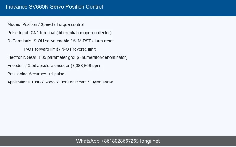
The Inovance SV660N series servo drive features a well-designed local human-machine interface that enables rapid on-site commissioning, parameter adjustment, and real-time status monitoring without requiring an external PC or commissioning software. Understanding the operation panel layout and the meaning of each status indicator is fundamental for efficient drive deployment and daily maintenance.
1.1 Panel Hardware Composition
The SV660N drive integrates a 5-digit 8-segment LED digital tube display capable of showing parameter codes, real-time monitoring values, fault codes, and operational status. This display is paired with a five-button keypad operator providing the following functions:
- MODE key: Sequentially switches between function code groups, allowing the user to navigate across parameter categories such as H00 (servo motor parameters), H01 (drive parameters), H02 (basic control parameters), and other functional groups.
- UP (Triangle) key: Increments the value of the currently blinking digit during parameter editing.
- DOWN (Inverted Triangle) key: Decrements the value of the currently blinking digit during parameter editing.
- SHIFT (Left Arrow) key: Moves the blinking digit to the left. When held down continuously, it provides page-turning functionality for displaying values exceeding five digits.
- SET key: Saves the modified parameter value and enters the next-level menu or confirms the current selection.
This button layout follows an intuitive convention common across industrial servo drives, minimizing the learning curve for field engineers who may work with multiple drive brands across different automation projects.
1.2 Status Indicator Lights
Beyond the digital display, the SV660N incorporates critical visual indicators for safe operation:
- CHARGE (Bus Voltage Indicator Light): This indicator illuminates when the DC bus capacitor retains electrical charge. Even when the main circuit power is turned OFF, the internal capacitors may still hold dangerous voltage levels. The manual explicitly warns that personnel must not touch power terminals while this light remains lit, as electric shock hazard persists. The discharge time depends on drive size and ambient conditions, and engineers must observe the waiting period specified on the product warning label before performing any wiring or maintenance operations.
For the SV660N-NS upgraded model, the communication network ports (CN3/CN4) include additional network status LEDs, providing visual confirmation of EtherCAT link activity and communication health—a significant improvement over the base SV660N model where such indicators were absent.
1.3 Panel Display Modes and Monitoring Parameters
The drive supports comprehensive panel monitoring through the H0B parameter group. Key monitoring values accessible from the front panel include:
| Parameter | Name | Unit | Description |
|---|---|---|---|
| H0b.53 | Position Deviation Counter (32-bit) | Command Units | Position deviation equals total input position commands minus total encoder feedback pulses (in command units). Critical for tuning positioning accuracy. |
| H0b.55 | Actual Motor Speed | 0.1 rpm | Real-time motor running speed with 0.1 rpm precision. Displays signed values for direction indication. |
| H0b.37 | Fault-Time Motor Speed | rpm | Captures motor speed at the moment a fault occurs, aiding post-failure analysis. |
| H0b.38 / H0b.39 | Fault-Time U/V Phase Current | A | Records U-phase and V-phase winding current RMS values at fault occurrence. |
| H0b.40 | Fault-Time Bus Voltage | V | DC bus voltage at fault moment (e.g., approximately 311.0 V after AC 220 V rectification, or 537.0 V after AC 380 V rectification). |
| H0b.41 | Fault-Time Input Terminal Status | – | Binary-coded status of all 5 DI terminals at fault occurrence, readable as hexadecimal value. |
| H0b.43 | Fault-Time Output Terminal Status | – | Binary-coded status of all 3 DO terminals at fault occurrence. |
The panel NRD (Not Ready) status display provides diagnostic information about why the drive cannot enter the ready state. The SV660N-NS enhanced model expands this from a single “nr” display to four distinct NRD sub-states (nr.1 through nr.4), each indicating a specific category of readiness-blocking conditions, significantly streamlining commissioning troubleshooting.
1.4 Panel-Related Fault Symptoms
Common panel anomalies documented in the troubleshooting chapter include:
- No display: Typically indicates loss of control power or severe hardware failure. Verify L1C/L2C control power supply.
- Display shows “88888”: Indicates abnormal display or processor self-test failure, often requiring power cycle or hardware inspection.
- Abnormal display: Garbled or incorrect characters may suggest electromagnetic interference affecting the display controller or defective display module.
2. Position Mode Control with External Pulse Input
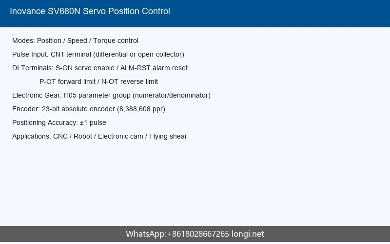
The SV660N series supports multiple operating modes compliant with CiA 402 device profile, including Cyclic Synchronous Position (CSP), Profile Position (PP), and traditional pulse-train position control through the CN1 control terminal. This section focuses on external pulse input position control, which remains widely used in standalone and PLC-controlled motion applications.
2.1 CN1 Control Terminal Overview
The CN1 terminal serves as the primary control interface for command input signals and general-purpose digital input/output signals. The terminal assignments support:
- Digital input signals (DI1-DI5): Configurable through parameter H03 group for functions such as Servo ON (S-ON), Alarm Reset (ALM-RST), Forward Over-travel (P-OT), Reverse Over-travel (N-OT), Home Switch, Emergency Stop, and Touch Probe triggers.
- Digital output signals (DO1-DO3): Configurable through parameter H04 group for functions including Servo Ready (S-RDY), Motor Rotation (TGON), Positioning Complete (COIN), Brake Output (BK), Warning (WARN), Alarm (ALM), Torque Reach (ToqReach), and Position Compare Output (CMP).
The DI logic level standards are specified in the manual, ensuring compatibility with both sourcing (PNP) and sinking (NPN) control systems. Proper logic configuration is essential—functions such as S-ON and ALM-RST must be configured with level-effective logic in non-bus control modes.
2.2 Digital Input Function Definitions
Key DI functions relevant to position control include:
| Function Code | Name | Active State | Application Note |
|---|---|---|---|
| FunIN.1 | S-ON (Servo Enable) | Active: Motor enabled; Inactive: Motor disabled | Only effective in non-bus control mode. Must use level-effective logic. |
| FunIN.2 | ALM-RST (Alarm Reset) | Active: Execute fault reset | Only effective in non-bus control mode. Recommended level-effective logic. |
| FunIN.14 | P-OT (Forward Over-travel) | Active: Forward drive prohibited | Prevents mechanical overrun. Use level-effective logic. |
| FunIN.15 | N-OT (Reverse Over-travel) | Active: Reverse drive prohibited | Prevents mechanical overrun in negative direction. |
| FunIN.31 | Home Switch | Active: Load within home switch range | Must use level-effective logic. Essential for homing operations. |
| FunIN.34 | Emergency Stop | Active: Zero-speed stop then position lock | Critical safety input. Recommended level-effective logic. |
| FunIN.38/39 | TouchProbe 1/2 | Active: Probe trigger enabled | Logic determined by probe function (60B8h), independent of terminal logic selection. |
2.3 Digital Output Function Definitions
Key DO functions for position control monitoring:
| Function Code | Name | Description |
|---|---|---|
| FunOUT.1 | S-RDY (Servo Ready) | Active when servo is prepared to receive S-ON signal; inactive when not ready. |
| FunOUT.2 | TGON (Motor Rotation) | Active when filtered motor speed absolute value reaches H06.16 setting. |
| FunOUT.5 | COIN (Positioning Complete) | Active when position deviation enters the in-position window. Fundamental for sequential motion control. |
| FunOUT.9 | BK (Brake Output) | Active: Drive outputs brake signal to release motor holding brake. |
| FunOUT.25 | CMP (Position Compare DO) | Active when servo passes target position comparison point. Used for high-speed position capture applications. |
2.4 Position Control Mode Configuration
For external pulse input position control, the following configuration workflow is recommended:
- Control mode selection: Set the drive to position control mode via the H02 parameter group or through EtherCAT object dictionary 6060h.
- Pulse input wiring: Connect the pulse train and direction signals from the motion controller to the designated CN1 pins. The SV660N supports differential pulse inputs compatible with standard industrial motion controllers.
- Electronic gear ratio setup: Configure H05 group parameters to establish the relationship between input pulse count and motor rotation angle (detailed in Section 3).
- DI/DO assignment: Map S-ON, alarm reset, over-travel limits, and positioning complete signals to appropriate CN1 terminals using H03 and H04 parameters.
- Positioning parameters: Set in-position window width, position command filter time constants, and maximum position deviation limits through H05 group parameters.
2.5 Fixed-Length Positioning Example
A typical fixed-length positioning application (such as in cutting machines or indexing tables) can be implemented as follows:
Assume a ball screw mechanism with 5 mm lead, requiring 0.001 mm positioning resolution. The motor encoder provides 8388608 pulses per revolution (23-bit absolute encoder). The electronic gear ratio must map each 0.001 mm command to the corresponding encoder count:
Gear Ratio Numerator / Gear Ratio Denominator = 8388608 / 5000
With the gear ratio configured, each input pulse from the PLC or motion controller corresponds to exactly 0.001 mm of linear travel. The COIN (positioning complete) output signals the controller when the axis reaches the target, enabling coordinated multi-axis sequences. The H0b.53 position deviation counter allows real-time verification that tracking error remains within acceptable bounds throughout the motion profile.
The SV660N additionally supports soft limit functionality (associated with H0A.01 parameter), providing software-based over-travel protection independent of hardware limit switches—a valuable secondary safety layer for fixed-length positioning systems.
3. Electronic Gear Ratio Setting and Calculation
The electronic gear ratio is one of the most critical parameters in servo position control systems, determining the scaling relationship between the motion controller’s command pulses and the servo motor’s actual mechanical displacement. Proper gear ratio configuration ensures that the commanded position accurately corresponds to the intended physical movement.
3.1 Concept and Significance
The electronic gear ratio effectively creates a programmable multiplier/divider between the pulse command input and the encoder feedback resolution. Rather than requiring mechanical gearboxes or pulley ratios to achieve desired motion scaling, the servo drive’s digital signal processing handles the conversion electronically. This provides:
- Flexibility to adapt the same servo motor to different mechanical transmission ratios without hardware changes
- Ability to use convenient command pulse units (e.g., 1 pulse = 0.01 mm) while maintaining full encoder resolution for internal control
- Simplified PLC programming by using integer pulse counts corresponding to meaningful mechanical units
3.2 Fundamental Calculation Formula
The electronic gear ratio calculation follows the principle of equating the mechanical travel per motor revolution with the command pulse count required to produce that travel:
Or expressed as fraction:
Numerator / Denominator = (Motor Encoder Pulses/Rev) / (Desired Command Pulses/Rev)
Where:
- Encoder Resolution: For the MS1-R series motors paired with SV660N, the 23-bit absolute encoder provides 223 = 8,388,608 encoder counts per revolution (also referenced as 8388607 in single-turn absolute position feedback parameters).
- Command Pulses per Revolution: Determined by the mechanical transmission ratio and the desired positioning resolution.
3.3 Practical Calculation Examples
Example 1: Direct Drive Rotary Table
For a direct-drive rotary table requiring 0.01 degree positioning resolution:
Gear Ratio = 8,388,608 / 36,000 = 233.016… → Set as fraction: Numerator=8388608, Denominator=36000
Simplified: Numerator=524288, Denominator=2250
Example 2: Ball Screw Linear Stage
For a stage with 10 mm lead ball screw, requiring 0.001 mm resolution:
Gear Ratio Numerator = 8,388,608
Gear Ratio Denominator = 10,000
Simplified: Numerator=524288, Denominator=625
Example 3: Belt Drive with Reduction
For a belt system with 3:1 reducer, 100 mm pulley circumference, requiring 0.1 mm resolution:
Pulses per 100 mm = 100 mm / 0.1 mm = 1,000 pulses
Pulses per motor revolution = 1,000 / 3 = 333.333…
To maintain integer arithmetic: Numerator=8388608×3=25165824, Denominator=1000
Or more practically: Numerator=8388608, Denominator=333.333 is not valid—recommend using Numerator=25165824, Denominator=1000, then simplify
3.4 SV660N Parameter Configuration
In the SV660N parameter system, the electronic gear ratio is configured within the H05 Position Control Parameter group. While the full parameter detail table was not completely extracted from the source document, the manual specifies that H05 group contains all position-loop related settings including:
- Gear ratio numerator and denominator parameters
- Position command source selection
- Pulse input format configuration (pulse + direction, CW/CCW, or AB phase)
- In-position window width (positioning completion threshold)
- Maximum position deviation limit (follow error protection threshold)
- Position command filter settings for smoothing
Engineers should access the H05 parameter group via the front panel (navigating with MODE key) or through the Inovance commissioning software connected via CN5 RS232 port. After modifying the gear ratio, a parameter save operation is required, and some changes may necessitate a drive restart to take effect.
3.5 Conversion Factor in EtherCAT Modes
When operating in EtherCAT CiA 402 modes such as CSP (Cyclic Synchronous Position) or PP (Profile Position), the “conversion factor” concept referenced in Section 13.1 of the manual serves an analogous purpose to the electronic gear ratio. Object dictionary entries define how user position units (e.g., 607Ah Target Position) map to encoder counts. The SV660N supports both linear and rotary position modes for absolute encoder systems, with parameter H0E.07 (in NS models) enabling selection between command unit systems and user unit systems—offering enhanced flexibility for machine builders developing integrated EtherCAT architectures.
4. Common Fault Codes and Troubleshooting
The SV660N incorporates a comprehensive fault management system with fault level classification, detailed fault code documentation, and systematic troubleshooting procedures. Understanding the fault hierarchy and typical failure modes is essential for minimizing machine downtime.
4.1 Fault Level Classification
The drive classifies anomalies into distinct severity levels (defined in Section 19.1 of the manual):
- Faults (Errors): Conditions that immediately disable the servo output and require explicit reset after the root cause is eliminated.
- Warnings (Alarms): Conditions indicating abnormal operation that may develop into faults if unaddressed, but do not immediately disable the drive.
The fault code format follows a structured numbering convention: a letter prefix (E for fault, W for warning if applicable) followed by a three-digit main code and a one-digit sub-code (e.g., E410.1, E122.0), enabling precise identification of failure categories and specific causes.
4.2 Fault Reset Procedures
After a fault occurs and the underlying cause has been corrected, the drive can be reset through multiple methods (Section 19.2):
- DI Reset: Activate the ALM-RST digital input (configured via H03 group) in non-bus control mode.
- Panel Reset: Use the front panel interface to acknowledge and clear the fault.
- Communication Reset: Send the appropriate reset command via EtherCAT SDO or through the RS232 commissioning interface.
- Power Cycle: Turn off main power, wait for the CHARGE indicator to extinguish completely, then re-energize.
4.3 Common Fault Codes and Resolution
The following table summarizes frequently encountered faults based on the fault code list and troubleshooting guidance from the manual:
| Fault Code | Fault Name | Probable Cause | Troubleshooting Action |
|---|---|---|---|
| E120 | Overcurrent / Short Circuit | Motor cable short; motor winding damage; excessive load; incorrect UVW wiring. | Check motor cable insulation; verify UVW phase sequence; inspect motor winding resistance; reduce load or acceleration rate. |
| E122.0 / E122.2 | Overcurrent (Software Detection) | Check parameter H00.08 setting; excessive current command; mechanical binding. | Verify current limit settings; inspect mechanical system for jamming; review torque demand vs. motor capacity. |
| E136.2 | Overload | Continuous operation above rated torque; mechanical efficiency degradation. | Verify load torque calculations; inspect gearbox lubrication; consider upsizing motor or reducing duty cycle. |
| E140.3 | Overvoltage | Excessive regenerative energy; insufficient braking resistance; high input voltage. | Add or verify external braking resistor (P+, C terminals); check mains voltage against drive rating; increase deceleration time. |
| E208.3 | Undervoltage | Low mains voltage; power dip; poor power supply capacity. | Measure input voltage under load; verify power supply capacity; check for loose power connections. |
| E320.0 / E321.0 | Encoder Communication / Data Fault | Encoder cable disconnection; poor shield grounding; CRC errors. | Inspect CN2 encoder cable connection; verify shield grounding at single point; check cable for damage. NS models provide H30.16-H30.18 counters for encoder communication diagnostics. |
| E410.1 | Excessive Position Deviation | Following error exceeds H05 group limit; insufficient torque; mechanical jam. | Check position deviation parameter limits; verify mechanical system; review gain tuning; inspect for binding. |
| E420.0 | Communication Timeout / Sync Loss | EtherCAT communication interruption; sync signal loss. | Inspect CN3/CN4 cabling; verify EtherCAT network topology; check controller sync master configuration. |
| E731.0 | Encoder Hot-Plug Detected | Encoder cable disconnected during operation. | Never hot-plug encoder cables. Power down before connecting/disconnecting encoder. Inspect CN2 connector integrity. |
| E740.0 / E740.2 | Encoder Fault | Encoder hardware failure or communication breakdown. | Check encoder cable and connector; replace encoder if cable tests pass. NS models distinguish fault sub-codes for more precise diagnosis. |
| E921.0 | System / FPGA Fault | Internal hardware or firmware anomaly. | Record fault context (H0b.34-H0b.43); contact Inovance technical support with captured fault history. |
| E941.0 | STO Safety Fault | STO circuit triggered unexpectedly. | Verify CN6 STO wiring; inspect safety relay contacts; ensure both STO1 and STO2 receive 24V simultaneously for normal operation. |
| E952.0 | Software Limit Exceeded | Position command exceeds H0A.01 soft limit boundaries. | Check soft limit parameter settings; verify homing was completed successfully; review motion program for out-of-range positions. |
| E663.0 / E664.0 | Internal Processing Fault | Firmware processing anomaly; parameter corruption. | Document fault occurrence conditions; perform parameter factory restore if safe; update firmware to latest revision. |
| EE08.2 / EE09.3 | EtherCAT Sync / Network Fault | No sync signal from master; distributed clock loss; invalid frames. | Verify controller supports DC sync; check cable shielding; monitor H0E.25-H0E.28 error counters on NS models. |
4.4 Diagnostic Parameter Usage
The H0B parameter group provides powerful diagnostic data capture. When a fault occurs, the drive automatically records:
- H0b.34: Current fault code (hexadecimal display, e.g., E941.0)
- H0b.35: Fault timestamp (total servo runtime in seconds at fault occurrence)
- H0b.37: Motor speed at fault moment
- H0b.38 / H0b.39: U-phase and V-phase currents at fault moment
- H0b.40: DC bus voltage at fault moment
- H0b.41: Digital input states at fault moment (binary encoded)
- H0b.43: Digital output states at fault moment (binary encoded)
For the SV660N-NS model, the fault record capacity is expanded from 10 groups to 20 groups, and the black box function supports continuous triggering with enhanced channel coverage including encoder data, EtherCAT status, and DO channel states—enabling significantly more effective post-mortem analysis of intermittent faults.
4.5 Common Troubleshooting Symptoms and Solutions
Beyond individual fault codes, the manual’s Chapter 21.2 addresses common operational symptoms:
- Motor does not rotate: Verify S-ON signal is active; check command source; confirm no active faults; verify UVW phase wiring matches motor nameplate.
- Panel shows “nr” (Not Ready): Check for active faults, incomplete initialization, or safety inputs (STO) active.
- Parameters cannot be modified: Verify drive is not in Run state; check parameter write-enable settings; confirm user privilege level.
- Controller cannot receive DO signals: Verify DO wiring polarity; check H04 output assignment; measure DO output voltage/current against load requirements.
- Brake does not release: Verify BK output assignment in H04; check brake power supply (typically 24VDC); inspect brake coil resistance.
- Signal interference: Use shielded twisted-pair cables; implement single-point grounding; add ferrite cores or EMI filters; separate power and signal wiring.
5. Conclusion
The Inovance SV660N series servo drive represents a mature, feature-rich motion control platform suitable for applications spanning semiconductor manufacturing, precision assembly, packaging machinery, CNC equipment, and automated material handling. With power ratings from 0.05 kW to 7.5 kW, integrated EtherCAT connectivity, and support for both standalone pulse-train control and networked synchronous multi-axis motion, the SV660N addresses a broad spectrum of industrial automation requirements.
The 5-digit LED operation panel provides intuitive local access to all drive functions, while comprehensive monitoring parameters (H0B group) deliver deep visibility into runtime behavior and fault conditions. The position control architecture—encompassing external pulse input through the versatile CN1 terminal, flexible DI/DO configuration, and precise electronic gear ratio scaling—enables rapid integration with existing PLC-based motion architectures.
Proper configuration of the electronic gear ratio is essential for achieving the commanded positioning accuracy, and the calculation methodology follows established servo engineering principles adapted to the SV660N’s 23-bit absolute encoder resolution. Engineers should carefully verify mechanical transmission ratios and desired command units before finalizing H05 parameter values.
The drive’s extensive fault diagnosis capabilities—from detailed fault code reporting to automated fault-context capture—significantly reduce mean-time-to-repair in production environments. The NS model enhancements, including expanded fault logging, continuous black box triggering, dedicated EtherCAT diagnostic counters, and refined encoder fault discrimination, provide even greater diagnostic depth for demanding applications.
Successful deployment of the SV660N requires attention to installation fundamentals: proper grounding, shielded cabling with single-point shield termination, adequate panel spacing for thermal management, and adherence to the CHARGE indicator safety protocol. By combining these practices with the functional knowledge presented in this guide, servo system engineers can maximize the performance and reliability of their SV660N-based motion control systems.
Technical content derived from Inovance SV660N Series General Servo Drive User Manual (Document PS00005512, Revision B06). For complete parameter tables, wiring diagrams, and the latest firmware-specific behavior, always consult the official manual available at the Inovance technical support portal.