
1. Background and Typical Fault Phenomenon
In practical field maintenance, overvoltage faults in variable frequency drives (VFDs) are common. However, a very specific and misleading condition is when the drive reports an overvoltage fault immediately after power-up, before the motor even starts.
Typical symptoms include:
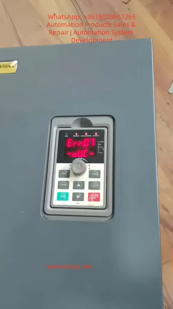
- Fault code displayed: Err.07 (Overvoltage during constant speed)
- Fault occurs immediately after power-on
- No motor operation or command given
- DC bus voltage reading: approximately 580V
- Voltage value is stable and does not fluctuate
This type of fault often leads to misdiagnosis, especially when technicians assume that overvoltage must be associated with regenerative energy or deceleration.
2. DC Bus Voltage Fundamentals
A VFD operates on an AC-DC-AC conversion principle. The incoming AC voltage is rectified and filtered to form a DC bus.
The theoretical relationship is:
[
U_{dc} \approx 1.35 \times U_{ac}
]
For a standard 380V three-phase system:
- Theoretical DC bus voltage ≈ 380 × 1.35 ≈ 513V
In real applications, considering fluctuations and ripple:
- Normal DC bus voltage range: 500V to 540V
Therefore, under no-load and idle conditions:
- The DC bus voltage should remain around 510V
- It should not naturally rise to 580V or higher
3. Two-Level Overvoltage Protection Mechanism
A common misconception is that overvoltage only occurs above 700V. In reality, VFDs implement a two-tier protection strategy:
3.1 Software-Level Protection
- Trigger range: approximately 580V to 620V
- Purpose: early intervention to prevent hardware damage
- Action: fault alarm and shutdown
3.2 Hardware-Level Protection
- Trigger range: approximately above 700V
- Purpose: protect IGBT modules and DC capacitors
- Action: emergency shutdown or hardware protection
Thus:
- A reading of 580V triggering a fault is technically correct
- However, it must represent a real voltage, not a false reading
4. Logical Contradiction in Power-Up Overvoltage
In a non-operational state:
- No motor rotation
- No deceleration process
- No regenerative energy feedback
There is no physical mechanism to increase DC bus voltage beyond its rectified value.
Therefore:
If a VFD reports 580V at power-up, the key question is:
Is the voltage real, or is the measurement incorrect?
5. Root Cause: Voltage Detection Circuit Error
In over 90% of such cases, the issue is not actual overvoltage, but a fault in the voltage sensing circuit.
The DC bus voltage is not measured directly. Instead, it is processed through a signal chain:
5.1 High-Voltage Divider Network
The high DC voltage (~500V) is reduced using a resistor divider:
- Typically consists of high-value resistors (hundreds of kΩ to MΩ)
- Output is scaled down to low voltage (e.g., 0–5V)
Failure modes:
- Resistance drift due to aging
- Leakage caused by moisture or contamination
Result:
- Divider ratio changes
- Output voltage increases
- MCU interprets voltage as higher than actual
5.2 Operational Amplifier Stage
The divided signal is conditioned using an op-amp:
- Buffering
- Amplification
- Filtering
Failure modes:
- Input offset drift
- Power supply instability
- Internal damage
Result:
- Amplified signal becomes inaccurate
- ADC receives incorrect voltage level
5.3 ADC and Reference Voltage
The conditioned signal is fed into the MCU’s ADC:
- Requires a stable reference voltage
Failure modes:
- Reference voltage drops
- ADC calibration shifts
Result:
- All measured values appear higher than actual
6. Key Differences: Real Overvoltage vs Measurement Error
| Feature | Real Overvoltage | Detection Error |
|---|---|---|
| Occurrence | During operation | At power-up |
| Voltage behavior | Dynamic | Stable |
| Load dependency | Yes | No |
| Value pattern | Fluctuating | Fixed abnormal value |
| Root cause | Energy feedback | Circuit drift |
The described case clearly matches the detection error scenario.
7. Practical Diagnostic Procedure
Step 1: Measure Input Voltage
Check three-phase input:
- R-S, S-T, R-T
Expected:
- Around 380V ±10%
If input exceeds 420V, a supply issue may exist.
Step 2: Measure Actual DC Bus Voltage
Using a multimeter:
- Measure between P+ and N-
Interpretation:
| Measured Value | Conclusion |
|---|---|
| ~510V | Detection circuit fault |
| ~580V | Real overvoltage |
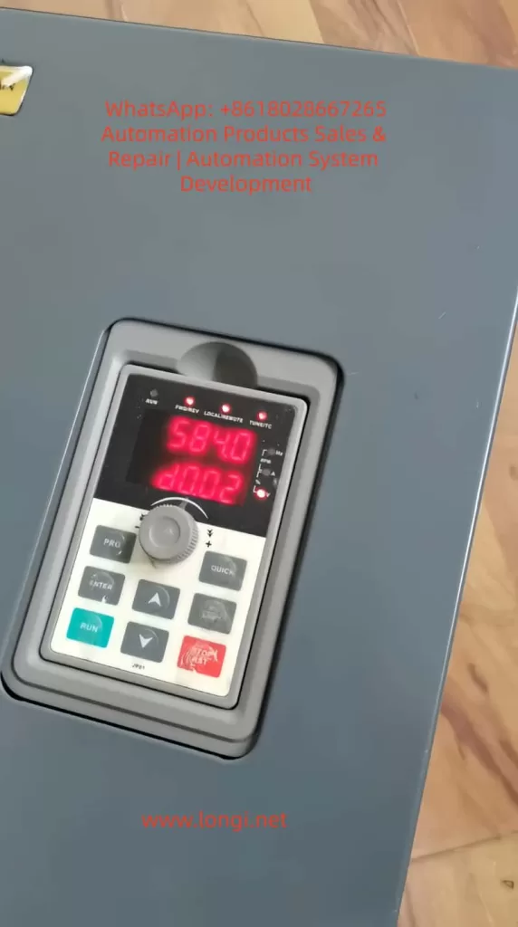
Step 3: Compare with Display Value
If:
- Multimeter shows 510V
- Display shows 584V
Conclusion:
Voltage sensing circuit is faulty
8. Component-Level Troubleshooting
8.1 Voltage Divider Resistors
- Check resistance values after power discharge
- Compare with nominal values
Focus:
- High-voltage side resistors are most prone to drift
8.2 Operational Amplifier
- Measure input and output voltages
- Verify linear relationship
If input is correct but output is high:
- Op-amp is defective
8.3 Reference Voltage
- Measure ADC reference (e.g., 2.5V or 3.3V)
If reference is lower than expected:
- ADC readings will appear higher
9. Why This Fault is Common
9.1 Thermal Stress
- Long-term heat exposure
- Causes resistor drift
9.2 Humidity and Contamination
- PCB surface leakage
- Insulation degradation
9.3 Aging
- Component parameter drift over time
- Solder joint degradation
10. Misdiagnosis Related to Braking Circuit
It is often assumed that overvoltage relates to braking resistor failure.
However:
- Braking circuits only operate during deceleration
- They are inactive at power-up
Therefore:
- A fault occurring immediately after power-on is not related to braking components
11. Key Maintenance Conclusions
- A 580V alarm is normal in terms of protection logic
- The real issue is why voltage reaches that level without operation
- Always verify DC bus voltage with a multimeter
- Voltage divider drift is the most probable cause
- Do not rely solely on displayed values
12. Practical Rule of Thumb
“Overvoltage at power-up = 90% probability of sensing circuit fault”
13. Conclusion
Understanding VFD overvoltage faults requires distinguishing between actual electrical conditions and measurement inaccuracies. In cases where faults occur immediately after power-up, the focus must shift from power circuits to sensing circuits.
By following a structured diagnostic approach—verifying real voltage, analyzing signal chains, and testing components—technicians can quickly and accurately locate the fault.
Effective troubleshooting depends not on interpreting fault codes alone, but on understanding the underlying electrical principles and circuit behavior.