
A Technical Case Study of a 7.5 kW Variable-Frequency Drive and Three-Phase Induction Motor
Introduction
Variable-frequency drives are widely used in fans, pumps, conveyors, mixers, machine tools, packaging machinery, and many other industrial systems. Their main functions include motor speed control, soft starting, torque regulation, energy saving, and electrical protection.
When a drive displays a fault code, the correct response is not to replace the drive immediately, repeatedly reset the fault, or disable the protection function. A reliable diagnosis must consider the fault code, motor nameplate data, drive capacity, operating current, load characteristics, parameter settings, wiring condition, and the exact stage at which the fault occurs.
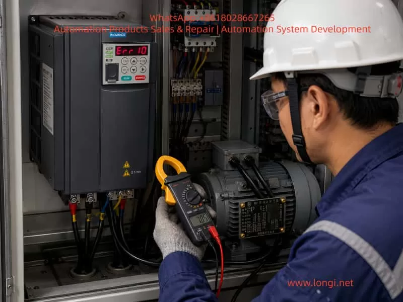
This article analyzes an actual case involving an Inovance MD310T7.5B variable-frequency drive operating a 7.5 kW three-phase induction motor. The drive displayed the fault code Err10.
The main equipment data are as follows:
- Drive model: Inovance MD310T7.5B
- Rated drive power: 7.5 kW
- Drive input: Three-phase AC 380–440 V
- Rated drive output current: Approximately 17 A
- Motor rated power: 7.5 kW
- Motor rated voltage: 380 V
- Motor rated current: 15 A
- Motor rated frequency: 50 Hz
- Motor rated speed: 1440 r/min
- Drive fault code: Err10
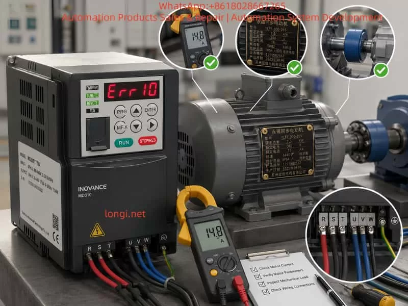
Based on the rated power and current, the drive and motor are generally matched. Therefore, the fault should not be attributed immediately to insufficient drive capacity. The actual cause may be related to mechanical overload, motor stall, incorrect motor parameters, improper wiring, poor cooling, abnormal power supply, or a defect in the drive’s current-detection circuit.
The following sections present a complete diagnostic method that can also be applied to many other induction-motor systems.
1. Meaning of Err10 on an Inovance MD310 Drive
On the Inovance MD310 series, Err10 means drive overload.
Typical causes include:
- Excessive mechanical load
- Motor stall
- Undersized drive capacity
The corresponding corrective actions are generally:
- Reduce the mechanical load
- Inspect the motor and driven equipment
- Use a drive with a larger capacity when necessary
A drive-overload fault is not exactly the same as an instantaneous overcurrent fault.
An overcurrent fault usually means that the output current has exceeded a hardware protection threshold within a very short period. A drive-overload fault normally indicates that the drive has carried excessive current for a certain duration, causing its internal thermal model or overload calculation to reach the protection limit.
For example, a brief current peak during acceleration may not trigger Err10. However, if the motor remains in a high-current condition for several seconds or minutes because of heavy load, slow acceleration, low-speed stalling, or mechanical blockage, the drive may eventually trip on overload.
Therefore, Err10 essentially means:
The drive has detected that its output current and overload duration have exceeded the permitted operating range.
This does not automatically mean that the drive is damaged. It means that the drive is protecting itself from prolonged electrical and thermal stress.
2. Why a 7.5 kW Drive Can Overload a 7.5 kW Motor
A common misunderstanding is that a 7.5 kW drive can always operate a 7.5 kW motor without overload. In practice, drive selection cannot be based on power alone.
The following factors must also be considered:
- Motor rated current
- Drive rated output current
- Motor starting torque
- Load torque characteristics
- Acceleration time
- Operating frequency
- Duty cycle
- Ambient temperature
- Installation altitude
- Frequency of starting and stopping
- Frequency of forward and reverse operation
- Mechanical inertia
- Shock-load conditions
In this case, the motor rated current is 15 A and the drive rated output current is approximately 17 A. The current margin is therefore only about 2 A.
If the motor normally operates at 15–16 A, even a relatively small increase in load may push the drive beyond its continuous current capability. This can happen because of:
- Increased mechanical friction
- Reduced supply voltage
- Short acceleration time
- Incorrect motor parameters
- Partial brake engagement
- Bearing deterioration
- Product buildup in the machine
- Improper motor connection
For constant-torque or impact-load applications, a drive with the same nominal power as the motor may not provide sufficient overload margin.
Applications that require particular attention include:
- Mixers
- Crushers
- Extruders
- Hoists
- Fully loaded conveyors
- Compressors
- Centrifuges
- Large-inertia rotating machinery
- Machines with frequent reversing
- Equipment that cannot start unloaded
Fans and centrifugal pumps usually have relatively favorable starting characteristics, but conveyors, mixers, hoists, and crushers may require considerably more starting torque.
Therefore, the correct selection principle is:
Compare both rated power and rated current, and evaluate the actual load profile rather than relying on the kW rating alone.
3. Difference Between Err10 and Err11
On the MD310 series:
- Err10: Drive overload
- Err11: Motor overload
The distinction is important.
Err10 protects the drive power section and its internal overload model. Err11 mainly protects the motor according to motor rated current and electronic thermal protection settings.
If a motor rated at 15 A is incorrectly configured as a 9 A motor, motor overload protection may operate too early. If the motor rated current is configured excessively high, the motor may not receive adequate protection and could overheat.
Therefore, technicians should confirm the exact fault code before starting diagnosis.
For Err10, the main concerns are:
- Excessive drive output current
- Mechanical overload
- Motor stall
- Insufficient drive capacity
- Current-measurement error
For Err11, the main concerns are:
- Motor electronic thermal protection
- Motor rated current setting
- Motor cooling
- Motor overload duration
The two faults may be caused by similar field conditions, but their protection targets and parameter relationships are different.
4. Determine When the Fault Occurs
The timing of the Err10 fault is one of the most useful diagnostic clues.
Before changing any parameter, determine whether the fault occurs:
- Immediately after power-up
- Immediately after pressing RUN
- During acceleration
- After reaching the commanded frequency
- After several minutes of operation
- Only under load
- Even under no-load conditions
- Every time or only intermittently
The operator should also be asked whether there was:
- Abnormal noise
- Reduced speed
- Vibration
- Burning smell
- Mechanical jamming
- Product buildup
- Recent motor replacement
- Recent drive replacement
- Recent parameter modification
- Recent maintenance on the gearbox or driven machine
4.1 Err10 Appears Immediately After RUN
If the drive trips almost immediately after receiving the run command, the likely causes include:
- Motor shaft locked
- Mechanical equipment jammed
- Electromagnetic brake not released
- Motor wiring short circuit
- Motor winding fault
- Incorrect star/delta connection
- Severe motor parameter error
- Drive current-detection fault
If the motor does not rotate and the current rises rapidly, the system is probably in a stalled condition.
4.2 Err10 Appears During Acceleration
If the motor starts but trips while increasing speed, inspect:
- Acceleration time
- Load inertia
- Starting load
- Motor torque capability
- Mechanical resistance
- Brake release
- Motor parameter identification
- Control mode
- V/f curve
A short acceleration time forces the motor to produce both load torque and acceleration torque. If the load inertia is high, the drive must supply excessive current for an extended period.
This is common in:
- Conveyors
- Centrifuges
- Large fans
- Mixers
- High-inertia rollers
- Heavy rotating tables
4.3 Err10 Appears After Several Minutes
If the machine starts and reaches full speed normally but trips after operating for several minutes, the likely causes are:
- Continuous overload
- Mechanical load gradually increasing
- Bearing temperature increasing
- Gearbox resistance increasing
- Product accumulation
- Drive cooling fan failure
- Blocked ventilation
- High cabinet temperature
- Low supply voltage
- Long-term operation close to the current limit
Although inadequate cooling may more commonly produce an overtemperature fault, poor cooling reduces the drive’s practical overload capability and can contribute to Err10.
4.4 Err10 Occurs Mainly at Low Frequency
Low-speed, high-torque operation is demanding for both the motor and the drive.
At low frequency:
- The motor’s shaft-mounted cooling fan turns slowly
- Motor cooling is reduced
- High current may be required to produce torque
- Incorrect motor parameters can cause weak torque
- The drive may remain in current limiting
- The motor may rotate slowly or stall
If the process requires continuous low-speed, high-torque operation, consider:
- An inverter-duty motor
- Forced external motor cooling
- A larger motor
- A larger drive
- Closed-loop vector control
- A mechanical reduction ratio change
5. Use the Fault History Data
The MD310 stores fault information and operating conditions at the time of the fault.
Useful parameters include:
- F9-14: First previous fault type
- F9-15: Second previous fault type
- F9-16: Most recent fault type
- F9-17: Output frequency at the most recent fault
- F9-18: Output current at the most recent fault
- F9-19: DC bus voltage at the most recent fault
- F9-20: Input terminal status at the most recent fault
Among these, F9-18 is especially important.
5.1 Fault Current Clearly Above 17 A
If the recorded current is significantly higher than the drive rated current, the overload is probably real.
Check:
- Mechanical blockage
- Excessive load
- Brake not released
- Motor stall
- Incorrect motor connection
- Short acceleration time
- High load inertia
5.2 Low Frequency and High Current
For example:
- Fault frequency: 5 Hz
- Fault current: 22 A
- Motor speed: Very low or zero
This strongly indicates:
- Motor stall
- Mechanical jamming
- Insufficient low-speed torque
- Incorrect motor parameters
- Brake engagement
- Incorrect star/delta connection
5.3 Near-Rated Frequency and High Current
If the fault occurs at 40–50 Hz and the current remains high, the machine is probably running under excessive working load.
Typical causes include:
- Conveyor overload
- Pump blockage
- High-viscosity material
- Fan impeller friction
- Tight belt
- Damaged bearing
- Gearbox problem
- Excessive production rate
5.4 Recorded Current Is Low but Err10 Still Occurs
If the stored current is not high and Err10 occurs repeatedly, inspect the drive itself.
Possible causes include:
- Current-sensor offset
- Hall sensor drift
- Current-sampling circuit fault
- Operational amplifier fault
- Control-board ADC error
- Internal connector fault
- Software or parameter corruption
Compare the drive display current with an external true-RMS clamp meter suitable for variable-frequency drive output.
If the drive displays 20 A while the external meter measures only 6 A, the current-detection circuit is likely inaccurate.
6. Check the Motor Nameplate Parameters
Accurate motor data are essential, especially in vector-control modes.
For this motor, the recommended basic values are:
| Parameter | Description | Recommended value |
|---|---|---|
| F1-00 | Motor type | Standard induction motor |
| F1-01 | Rated motor power | 7.5 kW |
| F1-02 | Rated motor voltage | 380 V |
| F1-03 | Rated motor current | 15.0 A |
| F1-04 | Rated motor frequency | 50.00 Hz |
| F1-05 | Rated motor speed | 1440 r/min |
6.1 Effect of Incorrect Rated Current
If F1-03 is set too low:
- Motor control may be inaccurate
- Torque may be insufficient
- Motor protection may operate too early
- Low-speed performance may be poor
If F1-03 is set too high:
- The motor may not be properly protected
- The control model may be inaccurate
- Motor temperature may rise excessively
- A real overload may be hidden
The rated current must not be increased simply to suppress an alarm.
6.2 Effect of Incorrect Rated Speed
A 1440 r/min motor at 50 Hz is typically a four-pole induction motor.
A four-pole motor has a synchronous speed of 1500 r/min at 50 Hz. The lower rated speed is normal because induction motors require slip to produce torque.
If the motor rated speed is incorrectly entered as:
- 960 r/min
- 1500 r/min
- 2900 r/min
The vector-control model may calculate slip and torque incorrectly.
6.3 Effect of Incorrect Rated Frequency
If a 50 Hz motor is configured as a 60 Hz motor, the voltage-to-frequency relationship may become incorrect.
This can cause:
- Reduced magnetic flux
- Insufficient torque
- Overexcitation
- Excessive current
- Poor motor performance
Every nameplate parameter should therefore be checked individually.
7. Perform Motor Parameter Identification
Motor auto-tuning or parameter identification is important when using sensorless vector control.
The drive may identify or estimate:
- Stator resistance
- Rotor resistance
- Leakage inductance
- Mutual inductance
- No-load current
7.1 Full Rotational Auto-Tuning
Where possible, disconnect the motor from the mechanical load.
Recommended procedure:
- Isolate the power supply.
- Disconnect the motor from the gearbox, belt, pump, or other driven equipment.
- Confirm that the motor shaft can rotate freely.
- Restore power.
- Select keypad control.
- Enter the correct motor nameplate parameters.
- Select full rotational identification.
- Press RUN.
- Keep personnel away from the motor.
- Wait until identification is completed.
During rotational identification, the motor may accelerate, decelerate, or change direction.
Safety precautions are essential:
- The motor must be firmly mounted.
- The shaft must not carry loose components.
- The machine must be mechanically disconnected.
- The brake must be released.
- Personnel must stay clear.
7.2 Static Identification
If the motor cannot be disconnected from the machine, static identification can be used.
This may be suitable for:
- Integrated pump units
- Large machinery
- Equipment where coupling removal is difficult
- Applications where motor rotation is not permitted during tuning
Static identification is useful, but full rotational identification usually provides more accurate control data.
7.3 Do Not Auto-Tune Before Basic Electrical Checks
Do not perform auto-tuning if:
- The motor winding resistance is unbalanced
- The motor insulation is poor
- The motor shaft is locked
- The brake is engaged
- The output cable is shorted
- The drive has an output-phase fault
Basic electrical and mechanical checks must be completed first.
8. Check the Motor Star/Delta Connection
Incorrect motor connection is a common cause of low torque, high current, and overload trips.
A standard three-phase motor normally has six terminals and can be connected in star or delta.
The correct connection depends on the voltage combination shown on the motor nameplate.
8.1 Motor Marked 220/380 V
This generally means:
- 220 V: Delta connection
- 380 V: Star connection
If such a motor is incorrectly connected in delta on a 380 V supply, each winding receives excessive voltage. The motor may draw very high current and overheat rapidly.
8.2 Motor Marked 380/660 V
This generally means:
- 380 V: Delta connection
- 660 V: Star connection
If such a motor is connected in star on a 380 V system, each winding receives insufficient voltage.
The motor may:
- Run under no load
- Produce weak torque
- Fail to accelerate under load
- Draw high current while stalled
- Trigger Err10
Therefore, a complete diagnosis requires inspection of:
- The full motor nameplate
- The six-terminal connection box
- The position of the terminal links
The rated voltage “380 V” alone is not enough to determine the correct connection.
9. Mechanical Inspection
In field service, mechanical problems are among the most common causes of Err10.
9.1 Check Whether the Motor Shaft Turns Freely
After isolating the power, manually rotate the motor shaft or coupling.
Abnormal findings include:
- Shaft cannot rotate
- One position feels locked
- Rotation is unusually heavy
- Metal scraping noise
- Excessive radial movement
- Excessive axial play
- Periodic sticking
9.2 Inspect the Gearbox
Common gearbox problems include:
- Insufficient lubrication
- Degraded lubricant
- Damaged gears
- Seized bearings
- Misalignment
- Excessive output load
- Broken internal components
A gearbox may still operate while developing excessive resistance. As temperature increases, the problem may become more severe and cause intermittent overload trips.
9.3 Inspect Belts and Chains
Belts or chains that are too tight can increase bearing load and mechanical friction.
Typical symptoms include:
- High no-load current
- Bearing overheating
- Slow acceleration
- Low-frequency stalling
- Heavy operating sound
Also check:
- Pulley alignment
- Chain condition
- Sprocket alignment
- Belt damage
- Eccentric pulleys
- Seized rollers
9.4 Inspect Pump Loads
For pump applications, check:
- Pump shaft condition
- Impeller blockage
- Mechanical seal seizure
- Bearing damage
- Incorrect rotation
- Valve position
- Process-fluid viscosity
- Pipe blockage
- Operation outside the pump design point
Different pump types respond differently to valve position. A closed discharge valve may overload some positive-displacement pumps, while centrifugal pumps behave differently. The actual pump type must be considered.
9.5 Inspect Fan Loads
For fans, check:
- Impeller rubbing
- Dust buildup
- Bearing condition
- Damper position
- Belt tension
- Impeller deformation
- Direction of rotation
- Operation above rated frequency
Fan power rises rapidly with speed. Increasing frequency beyond 50 Hz may increase motor load significantly.
9.6 Inspect Conveyor Loads
For conveyors, inspect:
- Belt misalignment
- Roller seizure
- Material accumulation
- Excessive belt tension
- Loaded starting
- Chain or gearbox resistance
- Coupling condition
- Frequent start-stop operation
Where possible, conveyors should start unloaded and receive material only after reaching stable speed.
10. Perform a No-Load Test
A no-load test is one of the most effective ways to distinguish a drive fault from a motor or mechanical fault.
10.1 Disconnect the Motor From the Machine
Disconnect:
- Coupling
- Belt
- Chain
- Gearbox connection
- Driven shaft
Then run the motor without mechanical load.
10.2 Motor Runs Normally Without Load
If the motor:
- Starts normally
- Reaches 50 Hz
- Draws current well below 15 A
- Runs smoothly
- Does not produce Err10
The drive and motor are probably serviceable, and the fault is most likely mechanical.
10.3 Motor Still Trips Without Load
If Err10 still occurs with the motor mechanically disconnected, check:
- Motor winding
- Motor bearings
- Motor connection
- Output cable
- Motor parameters
- Drive current display
- Drive current-detection circuit
- Power module
10.4 Drive Trips With the Motor Completely Disconnected
If the motor wires are removed from U, V, and W and the drive still reports overload during a brief test, the likely causes are internal:
- Current-sensor fault
- Current-sampling fault
- Driver-board problem
- Control-board problem
- Power-module defect
A no-motor test should be used only as a short diagnostic procedure.
11. Measure Motor Winding Resistance
After isolating the power, wait for the DC bus voltage to discharge. Allow at least the specified discharge time before touching the terminals.
Disconnect the motor cable from the drive.
Measure:
- U-V
- V-W
- W-U
The three readings should be approximately equal.
For example:
- U-V: 1.2 Ω
- V-W: 1.2 Ω
- W-U: 1.3 Ω
This is generally acceptable.
Abnormal examples include:
- One pair much lower than the others
- One pair open circuit
- Large imbalance between phases
Possible causes include:
- Winding short circuit
- Broken winding
- Loose terminal
- Damaged cable
- Internal motor connection fault
Because a 7.5 kW motor has relatively low winding resistance, a standard multimeter may not provide high accuracy.
A better method is to use:
- A milliohm meter
- A low-resistance ohmmeter
- A Kelvin bridge
When using a standard multimeter, short the test leads first and subtract the lead resistance.
12. Measure Motor Insulation Resistance
Poor insulation can cause leakage current, ground faults, unstable drive operation, and power-module damage.
Disconnect the motor and motor cable completely from the drive.
Use a 500 V insulation resistance tester to measure:
- U to motor frame
- V to motor frame
- W to motor frame
The insulation resistance should not be lower than the manufacturer’s minimum requirement. In practical maintenance, a healthy dry motor normally shows a value far above the minimum.
Important precautions:
- Never apply a megohmmeter directly to the drive output terminals.
- Disconnect all motor wires from the drive.
- Confirm that the motor is isolated.
- Discharge the winding after the test.
- Investigate moisture contamination when the insulation value is low.
If the insulation is poor, dry, clean, repair, or rewind the motor before further operation.
13. Check Output Current Balance
Use a true-RMS clamp meter suitable for PWM drive output.
Measure the three output phases:
- U
- V
- W
13.1 All Three Phases Balanced but Too High
This usually indicates:
- Mechanical overload
- Motor stall
- Excessive inertia
- Short acceleration time
- Incorrect motor parameters
- Low-speed high-torque operation
13.2 One Phase Is Significantly Different
Possible causes include:
- Unbalanced motor winding
- Loose terminal
- Damaged output cable
- Output module problem
- Current-sensor channel error
- Output-phase loss
13.3 Drive Display and Clamp Meter Differ Greatly
If the drive indicates 20 A but the external meter shows only 5–8 A, investigate:
- Hall current sensor
- Sampling resistor
- Operational amplifier
- Driver-board power supply
- ADC reference
- Internal connector
- Control-board current input
The external meter must be appropriate for variable-frequency drive output, because ordinary meters may not accurately measure PWM waveforms.
14. Check the Input Power Supply
Low or unbalanced input voltage can contribute to overload conditions.
Measure:
- R-S
- S-T
- T-R
The three line-to-line voltages should be balanced and within the drive’s rated range.
Also inspect:
- Circuit breaker contacts
- Contactor contacts
- Fuse condition
- Cable size
- Terminal tightness
- Input reactor
- Supply transformer capacity
A burned contactor contact may show normal voltage with no load but suffer a large voltage drop under load.
Low input voltage forces the system to draw more current to produce the same output power, especially under heavy-load conditions.
15. Increase the Acceleration Time for Testing
A short acceleration time is a frequent cause of high current.
During acceleration, the motor must provide:
- Load torque
- Friction torque
- Inertial acceleration torque
The larger the inertia, the greater the required torque and current.
As a diagnostic test, increase the acceleration time to approximately 20–30 seconds and observe the result.
If the fault disappears, the original acceleration time was likely too short for the machine.
However, acceleration time should not be increased indefinitely. If the motor remains in a low-frequency, high-current region for too long, overload may still occur.
The final setting should consider:
- Load inertia
- Starting torque
- Process requirements
- Motor thermal condition
- Mechanical limits
16. Avoid Continuous Low-Speed, High-Torque Operation
Standard induction motors are often unsuitable for prolonged low-speed, high-load operation without additional cooling.
At low speed:
- The shaft-mounted fan turns slowly
- Cooling is reduced
- Motor temperature increases
- Current may remain high
- Torque performance may become unstable
For demanding low-speed applications, consider:
- Inverter-duty motor
- Forced ventilation
- Larger motor
- Larger drive
- Encoder feedback
- Closed-loop vector control
- Mechanical speed reduction
Do not rely only on increasing torque boost or current limits. Excessive boost may cause magnetic saturation, high current, and overheating.
17. Inspect Drive Cooling and Installation
The following items should be checked:
- Cooling fan operation
- Fan speed
- Dust accumulation
- Heat-sink cleanliness
- Air inlet blockage
- Air outlet blockage
- Cabinet temperature
- Clearance above and below the drive
- Arrangement of multiple drives
- Cabinet filter condition
- Nearby braking resistors
- Ventilation system
High ambient temperature reduces the drive’s practical continuous-current capability.
Corrective measures may include:
- Cleaning air paths
- Replacing fans
- Adding cabinet ventilation
- Installing an air conditioner
- Increasing mounting clearance
- Relocating heat-generating components
- Derating the drive
18. When a Larger Drive Is Required
A larger drive may be justified if all of the following are confirmed:
- Mechanical equipment is normal
- Motor parameters are correct
- Motor auto-tuning is complete
- Motor connection is correct
- Input voltage is stable
- Motor winding and insulation are normal
- Current remains close to or above 17 A
- Process load cannot be reduced
If replacing the 7.5 kW drive with an 11 kW drive, the motor protection values must still be based on the actual 7.5 kW motor:
- Rated power: 7.5 kW
- Rated voltage: 380 V
- Rated current: 15 A
- Rated frequency: 50 Hz
- Rated speed: 1440 r/min
A larger drive must not be configured as though the motor were also 11 kW.
Otherwise, the motor may lose proper overload protection.
A larger drive is particularly beneficial for:
- Heavy starting loads
- Large inertia
- Frequent starting
- Frequent reversing
- Shock loads
- Long-term high-current operation
19. Do Not Defeat the Protection
Unsafe field practices include:
- Increasing the motor rated current without justification
- Disabling overload protection
- Increasing thermal limits excessively
- Repeatedly resetting the fault
- Restarting immediately after each trip
- Increasing torque boost excessively
- Increasing the current limit without diagnosis
- Installing a larger circuit breaker without correcting the cause
- Bypassing fault contacts
Err10 is the protection result, not the root cause.
Repeated forced starting under a stalled condition can damage:
- IGBT module
- Motor winding
- Output cable
- Contactor
- Coupling
- Gearbox
- Mechanical transmission
- Electrical cabinet
The correct approach is to identify why the current is high.
20. Recommended Standard Diagnostic Procedure
A systematic troubleshooting sequence for an MD310T7.5B driving a 7.5 kW motor is as follows.
Step 1: Record the Fault Condition
Record:
- Operating stage
- Load condition
- Frequency
- Current
- Sound
- Vibration
- Fault recurrence
- Recent maintenance or parameter changes
Step 2: Read Fault History
Check:
- F9-16
- F9-17
- F9-18
- F9-19
- F9-20
Step 3: Confirm Drive and Motor Ratings
Verify:
- Drive: 7.5 kW, approximately 17 A
- Motor: 7.5 kW, 15 A
- Supply: 380 V
Step 4: Check Motor Parameters
Set the motor data according to the nameplate.
Step 5: Inspect the Mechanical System
Check:
- Motor shaft
- Coupling
- Belt
- Chain
- Gearbox
- Bearings
- Brake
- Pump
- Fan
- Conveyor
Step 6: Perform a No-Load Test
Disconnect the mechanical load and run the motor alone.
Step 7: Test the Motor Electrically
Measure:
- Three-phase winding resistance
- Insulation resistance
- Cable continuity
- Star/delta connection
Step 8: Perform Motor Auto-Tuning
Use full rotational identification where possible.
Step 9: Increase Acceleration Time
Temporarily increase acceleration time and repeat the test.
Step 10: Measure Operating Current
Compare:
- Drive display current
- External clamp-meter current
- Motor rated current
- Drive rated current
Step 11: Inspect Cooling
Check fan, ventilation, dust, cabinet temperature, and installation clearance.
Step 12: Evaluate the Drive Hardware
If the motor and mechanics are normal, inspect:
- Current sensor
- Driver board
- Control board
- Sampling circuit
- Power module
21. Typical Diagnostic Examples
Example 1: Fault at 5 Hz During Starting
Observed condition:
- Motor hums
- Shaft barely moves
- Fault frequency is 5 Hz
- Fault current is 22 A
Likely cause:
- Motor stall
- Mechanical blockage
- Brake not released
- Incorrect motor connection
- Incorrect motor parameters
Example 2: Fault After Several Minutes at 40 Hz
Observed condition:
- Starting is normal
- Current remains at 16–18 A
- Load gradually increases
- Err10 occurs after several minutes
Likely cause:
- Genuine continuous overload
- Increasing process load
- Mechanical resistance
- Insufficient drive margin
Example 3: Motor Runs Normally After Removing the Belt
Observed condition:
- Err10 occurs with the machine connected
- Motor runs normally with the belt removed
- No-load current is approximately 4 A
Conclusion:
- Drive and motor are probably normal
- Mechanical load is the main fault source
Example 4: Err10 With Motor Disconnected
Observed condition:
- Motor cables removed
- Drive still displays abnormal current
- No real output current measured
Likely cause:
- Current-sensor fault
- Current-sampling fault
- Control-board fault
- Driver-board fault
Example 5: Fault After Motor Replacement
Observed condition:
- Original motor operated normally
- New motor has the same rated power
- New motor is marked 380/660 V
- Terminal box is connected in star
Likely cause:
- The motor should normally be connected in delta at 380 V
- Star connection causes insufficient torque
- The motor stalls under load
- Drive overload occurs
22. Verification After Repair
The repair should not be considered complete merely because the fault no longer appears.
22.1 No-Load Test
Confirm:
- Smooth starting
- Balanced current
- Normal sound
- Normal vibration
- Correct frequency and speed relationship
22.2 Gradual Load Test
Increase the load step by step and record:
- Current at 10 Hz
- Current at 20 Hz
- Current at 30 Hz
- Current at 40 Hz
- Current at 50 Hz
- Motor temperature
- Drive temperature
22.3 Continuous Operation Test
Run the equipment continuously for at least 30–60 minutes and monitor:
- Current stability
- Temperature rise
- Cooling fan operation
- Bearing temperature
- Gearbox temperature
- Recurrence of the fault
- Periodic shock loads
22.4 Record Final Parameters
Document:
- Basic frequency parameters
- Motor parameters
- Acceleration and deceleration times
- Control mode
- Frequency command source
- Run command source
- Protection settings
- Fault history
This record is valuable for future maintenance and troubleshooting.
Conclusion
Err10 on an Inovance MD310 drive means that the drive has entered an overload condition.
In a system using a 7.5 kW MD310T7.5B drive and a 7.5 kW, 380 V, 15 A induction motor, the drive and motor are nominally matched. Therefore, the first conclusion should not be that the drive is undersized.
A correct diagnosis should follow this sequence:
- Identify the operating stage at which the fault occurs.
- Read the fault frequency, current, and DC bus voltage.
- Verify the motor nameplate parameters.
- Check the star/delta connection.
- Inspect the mechanical system for blockage or excessive load.
- Perform a no-load test.
- Measure winding resistance and insulation resistance.
- Perform motor parameter identification.
- Increase acceleration time for testing.
- Compare the drive current display with actual measured current.
- Inspect the input power supply and cooling conditions.
- Investigate the drive current-detection and power circuits only after the motor and mechanical system have been excluded.
Err10 is not usually caused by a single component. It is the result of the interaction between the drive, motor, mechanical load, wiring, parameters, power supply, and thermal conditions.
A reliable repair therefore depends on structured measurement, controlled testing, and elimination of each possible cause. This method prevents unnecessary drive replacement, avoids repeated equipment damage, and provides a technically defensible basis for maintenance decisions.