
I. Introduction
In the field of industrial automation, servo drives serve as the core hub connecting controllers (PLCs, upper computers) and actuating motors. Their communication stability directly determines the continuous operation capability of production lines. The SES800 series servo drives, renowned for their high cost-effectiveness and precise motion control performance, are widely applied in scenarios such as machine tools, packaging machinery, textile equipment, and logistics conveyor lines. However, during long-term operation, the Er.SC1 serial port communication anomaly is one of the most frequently reported faults by users. This can range from causing equipment shutdown to triggering production accidents. This article provides a comprehensive breakdown of the Er.SC1 fault, covering its definition, root causes, resolution process, case studies, and preventive measures, offering engineers a practical troubleshooting guide.
II. The Essence of the Er.SC1 Fault: Serial Communication Link Interruption
1. Fault Code Definition
Er.SC1 is the serial port communication anomaly fault code for SES800 drives (“SC” stands for “Serial Communication”). According to the drive manual, this fault is triggered when the following situations occur:
- The serial communication link between the drive and external devices (PLCs, upper computers, HMIs) is interrupted.
- Communication data frame errors occur (e.g., checksum failures, baud rate mismatches).
- Communication anomalies are detected when fault alarm parameters are enabled.
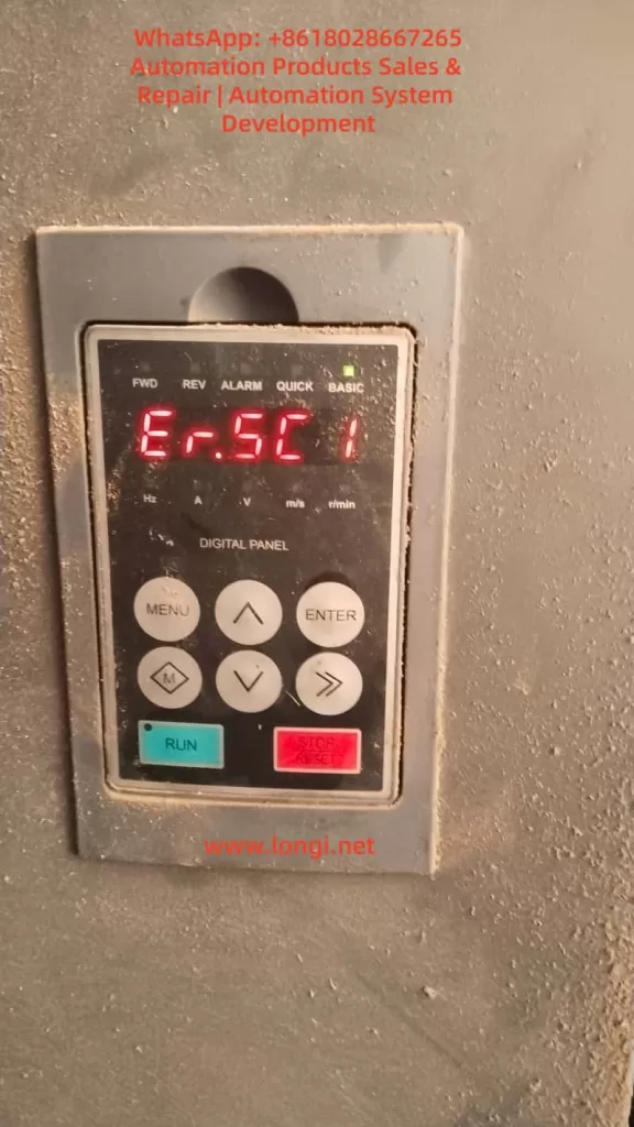
At this point, the drive stops motor output, and the operation panel displays “Er.SC1.” The fault can only be cleared by pressing the STOP/RESET key or resolving the underlying issue to resume operation.
2. The Role of Serial Communication Systems
The serial port of the SES800 (typically an RS485 interface, with some models supporting RS232) acts as the “nerve center” for interaction with external systems, performing the following functions:
- Instruction Transmission: Receiving control instructions from PLCs/upper computers (e.g., start, stop, speed setting, torque limiting).
- Status Feedback: Sending drive status information to external devices (e.g., current, voltage, rotational speed, fault codes).
- Parameter Configuration: Modifying drive parameters via the communication interface (e.g., PID gains, acceleration/deceleration times).
- Diagnostic Debugging: Using dedicated software (e.g., SES Studio) to read fault records and monitor real-time waveforms.
Once the communication link is interrupted, the drive cannot receive instructions or provide feedback, causing the system to enter “safe shutdown” mode and triggering Er.SC1.

III. The Four Core Causes of the Er.SC1 Fault
Based on the SES800 manual and field troubleshooting experience, the root causes of Er.SC1 can be summarized into four categories, ranked by frequency of occurrence:
1. Baud Rate/Communication Parameter Mismatch (40%)
The baud rate serves as the “speed benchmark” for serial communication. If the baud rates of the drive and external device are inconsistent, data frame synchronization errors occur—where a “1” sent by the transmitter may be misinterpreted as a “0” by the receiver, ultimately leading to communication failures.
Key Parameters:
- P15.03: Communication baud rate selection (default value for SES800-4T45 is 9600 bps).
- P97.00: Fault alarm enable (bit0 = serial port communication fault alarm, 1 = enabled, 0 = disabled).
- External device parameters: Baud rate, data bits (typically 8), stop bits (typically 1), and parity bits (typically none/even parity) for PLCs/upper computers.
Case Study: A machine tool factory’s SES800 drive connected to a Siemens S7-200 PLC triggered Er.SC1 because the PLC’s baud rate was set to 115200 bps, while the drive’s P15.03 remained at the default 9600 bps. As a result, the PLC’s instructions could not be interpreted by the drive, causing the fault.
2. Serial Communication Line Faults (30%)
Line issues are among the most common “hidden faults” in industrial settings, including:
- Loose/Oxidized Connections: Unsecured terminal block screws or oxidized interface pins (especially for outdoor equipment).
- Line Damage/Short Circuits: Cables squeezed by machinery, gnawed by rodents, or with damaged shielding leading to signal interference.
- Missing Terminal Resistors: RS485 buses require 120Ω terminal resistors connected in parallel at both ends (some models have built-in resistors, while others require external ones). Failure to do so can cause signal reflections.
- Electromagnetic Interference (EMI): Communication lines running parallel to inverter or motor power lines, resulting in crosstalk.
Case Study: A packaging machinery factory’s SES800 drive used ordinary twisted-pair cables (unshielded) for communication, running parallel to inverter power lines. Field testing revealed that the RS485 signal was superimposed with high-frequency noise (amplitude up to 3V), causing data frame checksum errors and triggering Er.SC1.
3. Upper Computer/External Device Faults (20%)
If the upper computer (industrial PC, HMI) or PLC is not functioning properly, the drive cannot establish a communication link, also triggering Er.SC1. Common scenarios include:
- The upper computer software is not launched/has crashed (e.g., operator accidentally closed the software).
- Mismatched communication protocols between the upper computer and drive (e.g., drive uses Modbus RTU, while upper computer uses Modbus ASCII).
- Incorrect IP address/port settings for the upper computer (for network-based communication).
- PLC program logic errors (e.g., failure to send a “communication enable” instruction).
Case Study: A logistics conveyor line’s SES800 drive triggered Er.SC1 because the upper computer (industrial PC) automatically restarted during a system update, failing to launch the communication software. Restarting the software resolved the fault.
4. Drive Communication Module Damage (10%)
If the above causes are ruled out, consider hardware faults in the drive’s communication module:
- Burnt RS485 chips (e.g., MAX485) due to overvoltage or electrostatic discharge.
- Oxidized/bent pins at the serial port interface (caused by frequent plugging/unplugging).
- Damaged capacitors/resistors in the communication circuit (e.g., failed filtering capacitors).
IV. Step-by-Step Resolution Guide for the Er.SC1 Fault
The following is a standardized troubleshooting process (ranked by priority) to help engineers quickly locate the issue:
Step 1: Confirm Fault Phenomena and Context
- Check the operation panel: Does it display “Er.SC1”? Are there any accompanying faults (e.g., overcurrent, overvoltage)?
- Inquire with operators: Were any parameters modified before the fault occurred? Was the communication line replaced? Did the upper computer exhibit any anomalies?
- Check equipment status: Is the motor shut down? Does the upper computer display a “communication interruption” message?
Step 2: Investigate Upper Computer/External Device Status
Objective: Confirm whether the external device is functioning properly and sending instructions to the drive.
- Check the upper computer: Is the software launched? Does it indicate “communication normal”?
- Check the PLC: Is the program running? Are there any “communication fault” alarms?
- Test instruction transmission: Use the upper computer to send a “jog” instruction and observe whether the drive responds (e.g., panel displays “RUN”).
Case Study: A textile factory’s SES800 drive triggered Er.SC1 due to a virus-induced crash of the upper computer software, which went unnoticed by the operator. Restarting the software resolved the fault.
Step 3: Inspect Communication Lines
Objective: Confirm whether the lines are connected and free from interference.
Power-Off Inspection:
- Unplug the communication line and use a multimeter to measure the A-B resistance at the drive end (normal value should be 120Ω if terminal resistors are present).
- Check terminal blocks for loose connections or oxidized pins. Clean and retighten them with alcohol wipes.
- Inspect the line for damage or exposed shielding (ensure the drive end is grounded).
Power-On Inspection:
- Use a multimeter to measure the RS485 signal voltage (A-B differential voltage should be 2–5V).
- Use an oscilloscope to measure the signal waveform (normal waveform is an inverted square wave with consistent amplitude and no noise).
- Replace the line with a spare shielded twisted-pair cable and observe whether the fault disappears.
Case Study: A machine tool factory’s SES800 drive had loose terminal block connections due to vibration. Tightening the terminals resolved the Er.SC1 fault.
Step 4: Verify Baud Rate/Communication Parameters
Objective: Ensure parameter consistency between the drive and external device.
- Check drive parameters:
- Press the “MENU” key to enter parameter mode and locate “P15.03” (baud rate).
- Record the current value (e.g., 9600) and compare it with the external device’s baud rate (e.g., PLC’s 115200).
- Modify parameters:
- Use the up/down keys to select the correct baud rate (e.g., 115200 corresponds to P15.03 = 4).
- Press “ENTER” to confirm and “MENU” to exit.
- Power cycle the drive and check whether the fault disappears.
Note: Before modifying the baud rate, ensure the external device’s data bits, stop bits, and parity bits match those of the drive (typically 8-1-N).
Step 5: Check Fault Alarm Parameters
Objective: Confirm whether “false alarms” are occurring due to parameter settings.
- Check the “P97.00” parameter (fault alarm enable):
- bit0: Serial port communication fault alarm (1 = enabled, 0 = disabled).
- If bit0 = 1 and the communication link is normal, it may be a “false alarm” (e.g., due to interference).
- Temporary solution: Set P97.00’s bit0 to 0 (disable alarm) and observe whether the fault is still triggered (if not, the issue is interference; if yes, the link is truly interrupted).
Step 6: Advanced Troubleshooting (Tool-Assisted)
If the above steps are ineffective, use professional tools to locate the issue:
- Serial Port Debugging Assistant: Connect to the drive’s serial port and send Modbus instructions (e.g., 0x03 to query motor current). Observe the replies:
- No reply: Line disconnection or communication module damage.
- Error reply (e.g., CRC error): Baud rate mismatch or line interference.
- Correct reply: Communication is normal; the fault may stem from upper computer logic.
- Logic Analyzer: Capture communication data packets and analyze frame structure (start bit, data bits, stop bit, parity bit) for correctness and the presence of “error frames” (e.g., incorrect frame length, checksum failures).
- Replacement Method: Replace the original drive with a same-model drive. If the fault disappears, the original drive’s communication module is damaged; if the fault persists, the issue lies with the external device or line.
Step 7: Reset and Recovery
- After resolving the fault, press the operation panel’s “STOP/RESET” key to reset.
- Restart the upper computer/PLC and send an “enable” instruction.
- Observe the drive panel: Does it display “RUN”? Are there any new faults?
V. Typical Case Studies
Case 1: Baud Rate Mismatch Causing Frequent Shutdowns
Scenario: An SES800-4T45 drive at a packaging machinery factory, connected to a Mitsubishi FX3U PLC, frequently triggered Er.SC1.
Troubleshooting:
- Checked upper computer: PLC program running normally, no alarms.
- Checked lines: RS485 cables securely connected, shielding grounded.
- Reviewed parameters: Drive’s P15.03 = 9600, PLC’s baud rate = 115200.
- Modified parameters: Changed drive’s P15.03 to 115200 (option 4).
Result: Fault disappeared, and the equipment ran continuously for 3 months without recurrence.
Case 2: Electromagnetic Interference Causing Occasional Faults
Scenario: An SES800 drive on a logistics conveyor line triggered Er.SC1 daily at 9 AM (when inverters started).
Troubleshooting:
- Checked lines: Communication lines ran parallel to inverter power lines (spacing < 10 cm).
- Detected signals: Used an oscilloscope to measure RS485 signals, finding 1 kHz noise superimposed (amplitude 3V).
- Implemented corrections: Replaced communication lines with shielded twisted-pair cables, maintained a spacing of > 30 cm from power lines, and grounded the shielding at one end.
Result: Noise disappeared, and Er.SC1 faults ceased.
Case 3: Upper Computer Software Crash Causing Shutdowns
Scenario: An SES800 drive at a machine tool factory triggered Er.SC1 due to an upper computer (industrial PC) automatically restarting during a system update.
Troubleshooting:
- Checked upper computer: Software failed to launch automatically (operator had not set “auto-start”).
- Tested: Manually launched the software and sent an “enable” instruction; drive resumed normal operation.
- Preventive measure: Set software to “auto-start” and added a “watchdog” program (automatically restarts software if it crashes).
Result: Fault did not recur.
VI. Preventive Measures for the Er.SC1 Fault
1. Line Maintenance
- Inspect communication lines monthly for loose terminals, line damage, and proper shielding grounding.
- Use shielded twisted-pair cables (RS485-specific) and avoid running them parallel to power lines.
- Install terminal resistors: If the bus length exceeds 100 meters, connect 120Ω resistors in parallel at both ends (confirm whether the model has built-in resistors).
2. Parameter Management
- Back up current parameters before modifying communication parameters (using the operation panel or SES Studio software).
- Maintain a “parameter ledger” to record baud rates, protocols, and upper computer addresses for each drive.
- Prohibit unauthorized personnel from modifying critical parameters such as P15.03 and P97.00.
3. Upper Computer Management
- Designate a dedicated operator for the upper computer to prevent accidental software shutdowns or setting changes.
- Install antivirus software on the upper computer and update the system regularly.
- Set a “communication timeout alarm”: If no reply is received from the drive within 10 seconds, the upper computer prompts a “communication interruption” message.
4. Electromagnetic Interference Protection
- Keep communication lines away from interference sources such as inverters, motors, and transformers (spacing > 30 cm).
- Ground the drive enclosure (grounding resistance < 4Ω).
- Use isolated communication modules (e.g., USB-to-RS485 isolators) to avoid ground loop interference.
5. Regular Maintenance
- Clean drive dust quarterly (especially at the serial port interface).
- Test the communication module annually: Use a serial port debugging assistant to send instructions and verify correct replies.
- Replace aging lines: If lines have been in use for over 2 years, replace them with new shielded cables.
VII. Safety Precautions
- Power-Off Operation: Before inspecting lines or parameters, disconnect the drive’s power (both main and control power) and wait at least 10 seconds (for capacitor discharge).
- Electrostatic Discharge (ESD) Protection: Wear an ESD wrist strap when handling communication modules to avoid damaging chips with static electricity.
- Tool Usage: When measuring voltage with a multimeter, select the correct range (RS485 voltage is 2–5V; avoid using high-voltage ranges).
- Professional Repairs: If the communication module is damaged, return it to the manufacturer or an authorized repair center. Do not attempt to replace chips yourself (risk of secondary faults).
VIII. Conclusion
The Er.SC1 fault serves as a “communication warning light” for SES800 servo drives, with its root causes typically stemming from parameter mismatches, line issues, or external device faults. By following a “software-first, hardware-second” troubleshooting process (upper computer → line → parameters → hardware), over 90% of faults can be resolved quickly. Prevention focuses on standardizing line installation, strict parameter management, and enhancing upper computer maintenance—measures that can reduce the occurrence of Er.SC1 by over 80%.
For engineers, mastering Er.SC1 troubleshooting methods not only enables rapid production recovery but also allows for system design optimization (e.g., adjusting line routing, upgrading shielding measures) through “fault复盘” (fault review) to improve equipment reliability. As industrial IoT (IIoT) becomes more prevalent, SES800’s communication functions will increasingly rely on networks (e.g., EtherCAT, Profinet), but serial ports will remain critical for the “last mile” of connectivity. Prioritizing basic communication stability is essential for supporting more complex smart manufacturing systems.
Appendix: Key Communication Parameters for SES800
| Parameter Number | Parameter Name | Options/Range | Default Value |
|---|---|---|---|
| P15.03 | Communication Baud Rate | 0 = 9600, 1 = 19200, 2 = 38400, 3 = 57600, 4 = 115200 | 0 (9600) |
| P15.04 | Communication Timeout | 0–65535 (unit: 10 ms) | 100 (1 s) |
| P97.00 | Fault Alarm Enable | bit0 = Serial Port Comm Fault (1 = enabled) | 1 (enabled) |
| P97.01 | Comm Fault Action | 0 = Alarm without Shutdown, 1 = Alarm with Shutdown | 1 (shutdown) |
(Note: Parameters are based on the SES800-4T45 manual and may vary slightly for different models.)
By following this guide, engineers can systematically resolve Er.SC1 faults, minimize downtime, and improve equipment operational efficiency.