
Introduction
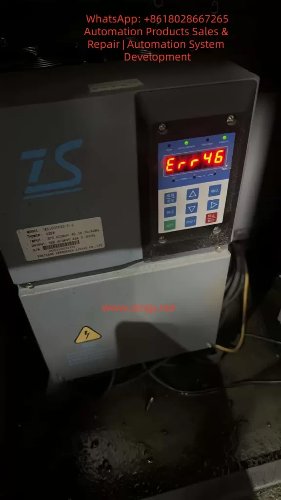
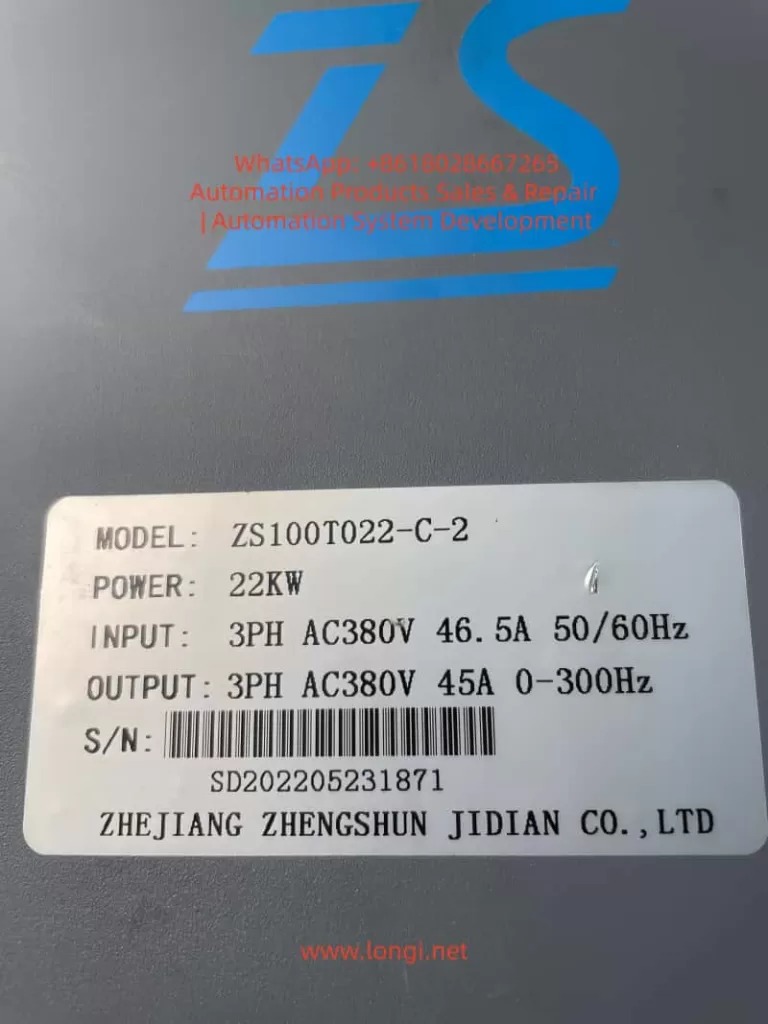
In the field of industrial automation, servo drives serve as the core hub between hydraulic systems and motor control. Their stability directly determines the production efficiency of equipment such as machine tools, injection molding machines, and packaging machinery. As a mainstream product in the domestic low-to-mid-end market, the Zhensun Servo ZS100 series is widely used in various hydraulic drive scenarios due to its high cost-performance ratio. However, ERR46 (Hydraulic Pressure Sensor Fault) is one of the most frequently reported issues by users. This fault causes the servo system to shut down immediately, potentially interrupting production processes or, in severe cases, damaging hydraulic components (e.g., pumps, valves).
This article combines Zhensun Servo technical documentation, on-site maintenance cases, and sensor principles to provide a comprehensive breakdown of the ERR46 fault from four dimensions: fault mechanism, cause investigation, resolution steps, and preventive measures, offering maintenance personnel an actionable troubleshooting guide.
1. The Underlying Logic of ERR46: The “Perception-Feedback” Mechanism of the Hydraulic Pressure Sensor
To resolve ERR46, one must first understand the role of the hydraulic pressure sensor and the drive’s fault-triggering logic.
1.1 Core Function of the Hydraulic Pressure Sensor
The hydraulic pressure sensor acts as the “nerve ending” of the hydraulic system. Essentially, it is a pressure-to-electrical signal converter. The ZS100 series typically employs piezoresistive sensors (low cost, high reliability). The working principle is as follows: when hydraulic oil pressure acts on the sensor’s sensitive diaphragm, the diaphragm deforms, causing a change in the resistance of the internal piezoresistive elements. This change is converted into a 0-10V DC analog signal (or 4-20mA for some models) via a Wheatstone bridge and fed back to the servo drive.
The drive adjusts the motor speed based on this signal to ensure the hydraulic system pressure remains stable within the set range (e.g., 10-15MPa for machine tool clamping mechanisms, 0.5-1MPa for lubrication systems). For example:
- When clamping cylinder pressure is insufficient, the drive increases motor speed to boost the pump’s output pressure.
- When the pressure reaches the set value, the drive reduces speed to maintain constant pressure.
1.2 Trigger Conditions for ERR46
The ZS100 series drive collects sensor signals through analog input channels (e.g., parameter L0.11). Internal signal detection circuits monitor the following metrics in real-time:
- Range: Whether the sensor signal exceeds the drive’s set threshold (e.g., if 0-10V corresponds to 0-10MPa, a signal exceeding 10V triggers an over-range alarm).
- Signal Stability: Whether signal fluctuation exceeds 0.5V within 1 second (e.g., signal jitter caused by vibration).
- Signal Continuity: Whether “signal loss” occurs (e.g., wiring disconnection resulting in a sustained 0V signal for over 1 second).
- Parameter Matching: Whether the sensor’s zero point (voltage at no pressure) and full scale (voltage at max pressure) match the drive parameters.
If any of these metrics are abnormal, the drive triggers an ERR46 fault and cuts off motor output to prevent the hydraulic system from running out of control and damaging equipment.
2. Common Causes and Troubleshooting Process for ERR46
Based on field maintenance data, the top three causes of ERR46 are: loose wiring (45%), sensor damage (30%), and parameter errors (20%). The remaining 5% are attributed to internal drive circuit faults (e.g., damage to the analog input module). Below is the standardized troubleshooting process:
2.1 Step 1: Safety First (Mandatory!)
Servo drives contain high-voltage capacitors (which may retain over 300V even after power-off). Before operation:
- Disconnect the drive’s main power supply (AC380V).
- Wait for 5 minutes to allow the capacitors to discharge.
- Use a multimeter to measure the voltage at the drive terminals (e.g., L1, L2, L3) to confirm they are de-energized before proceeding.
2.2 Step 2: Check Sensor Wiring (Most Common Cause)
Wiring issues are the “number one killer” of ERR46 faults, especially in high-vibration environments (e.g., machine tools) where terminal looseness and cable damage are common.
Troubleshooting Steps:
- Locate Terminals: Open the drive panel and find the hydraulic pressure sensor terminals (usually marked “PRESSURE SENSOR” or “OIL PRESSURE,” corresponding to terminals like X3-1 (+24V), X3-2 (Signal Output), X3-3 (0V/GND)).
- Check for Looseness: Gently shake the terminals with a screwdriver. If poor contact between the terminal and wire core is found (e.g., exposed core), re-crimp or replace the terminal.
- Check Cable Integrity: Inspect the sensor cable for crushing, breaking, or fraying (especially near bends close to the sensor or drive). Use a multimeter continuity setting to test the cable (signal wire resistance should be <0.5Ω).
- Check Shielding: The sensor cable must be shielded, with the shield grounded at a single point (drive side) to avoid electromagnetic interference (e.g., crossing motor cables and sensor cables causes signal fluctuation).
Case Study: A CNC lathe user reported an ERR46 fault. Inspection revealed that the signal wire terminal (X3-2) was loose due to vibration, causing poor contact between the core wire and terminal. After tightening the terminal and wiping the oxidation layer with alcohol, the fault was resolved.
2.3 Step 3: Test Sensor Output Signal (Core Cause)
If wiring is normal, verify if the sensor can perceive pressure correctly. The standard output for ZS100 series sensors is: 0MPa = 0V, Full Scale (e.g., 10MPa) = 10V, with a linear relationship between output and pressure.
Troubleshooting Steps:
- Power the Sensor: The sensor requires an external 24V DC power supply (if not provided by the drive, supply separately; note polarity: Red to +24V, Black to 0V).
- Apply Pressure: Use a manual pump or the equipment’s hydraulic system to apply pressure to the sensor (gradually increasing from 0MPa to full scale).
- Measure Output: Use a multimeter DC voltage setting to measure the signal terminal (X3-2) and observe voltage changes:
- Normal: Voltage increases by 1V for every 1MPa increase in pressure (e.g., 10MPa corresponds to 10V).
- Abnormal 1: Voltage remains 0V → Sensor power not connected or internal short circuit.
- Abnormal 2: Voltage remains 10V → Sensor range setting error or internal open circuit.
- Abnormal 3: High voltage fluctuation (e.g., >0.5V within 1s) → Aging of sensitive elements or interference.
- Abnormal 4: Non-linear voltage (e.g., pressure increases but voltage stays flat) → Damaged piezoresistive chip.
Case Study: An injection molding machine triggered ERR46. Testing revealed the sensor output remained at 0V even when pressure was applied (it should be 0V at no pressure but increase under load). Replacing the piezoresistive sensor (0-10V, 0-10MPa) resolved the fault.
2.4 Step 4: Check Drive Parameters (Often Overlooked)
Parameter errors can cause the drive to misjudge a normal sensor signal. Key parameters related to the hydraulic pressure sensor in the ZS100 series are:
| Parameter No. | Parameter Name | Description |
|---|---|---|
| L0.11 | Analog Input Channel Selection | Selects the channel for the pressure sensor (e.g., “1” for X3 terminal) |
| L0.12 | Sensor Range Setting | Sets the pressure value corresponding to full scale (e.g., “10.0” for 10MPa) |
| L0.13 | Sensor Zero Offset | Voltage at no pressure (default 0.0V) |
| L0.14 | Sensor Full Scale Offset | Voltage at max pressure (default 10.0V) |
| L0.15 | Sensor Self-Learning Enable | Set to “1” to enable self-learning (calibrates zero/full scale) |
Troubleshooting Steps:
- Enter Parameter Mode: Press the “Programming” key on the panel and enter the password (default “1234”).
- Check L0.11: Confirm the correct analog channel is selected (e.g., “1” for X3 terminal).
- Check L0.12: Confirm the range matches the sensor (e.g., “10.0” for a 0-10MPa sensor).
- Check L0.13/L0.14: Confirm zero (0.0V) and full scale (10.0V) are at defaults (if modified, restore them).
- Restore Factory Settings: If parameters are chaotic, set L9.00 (Factory Reset) to “1” and restart the drive to restore defaults.
Case Study: A packaging machine operator accidentally changed L0.12 from “10.0” to “5.0”. The drive interpreted the full-scale pressure as 5MPa. When actual pressure reached 6MPa (outputting 6V), the drive judged it as “over-range” and triggered ERR46. Restoring L0.12 to “10.0” fixed the issue.
2.5 Step 5: Factory Reset and Self-Learning (Ultimate Solution)
If the above checks fail, the issue may be sensor characteristic changes (e.g., zero drift due to aging) or corrupted drive parameters. Re-calibration via self-learning is required.
Operation Steps:
- Restore Factory Settings: Set L9.00 to “1” and restart the drive (parameters return to default).
- Enable Self-Learning: Set L0.15 to “1”.
- Collect Zero Signal: Open the hydraulic system relief valve to ensure 0MPa pressure. The drive automatically collects the zero-point voltage (e.g., 0V) and saves it to L0.13.
- Collect Full Scale Signal: Close the relief valve and apply full-scale pressure (e.g., 10MPa) to the system. The drive collects the full-scale voltage (e.g., 10V) and saves it to L0.14.
- Exit Self-Learning: Set L0.15 to “0” and save parameters (press “Confirm”).
Note: Ensure correct wiring and stable power before self-learning. Inaccurate results will occur if pressure exists during zero collection (causing subsequent signal offsets).
3. Preventive Measures for ERR46: From “Passive Repair” to “Active Prevention”
The root cause of ERR46 is often poor daily maintenance. The following measures can reduce the failure rate by 80%:
3.1 Daily Maintenance: Regular Inspections
- Weekly: Check if sensor terminals are loose and if cables are damaged.
- Monthly: Wipe the sensor surface with alcohol to remove oil and dust, preventing contamination of sensitive elements.
- Quarterly: Calibrate the sensor using a standard pressure source (e.g., piston manometer) to ensure output accuracy (error ≤ ±1%).
- Semi-Annually: Check the stability of the sensor power supply (24V DC); voltage fluctuation should not exceed ±5%.
3.2 Operational Standards: Avoid Misoperation
- Prohibit Arbitrary Parameter Changes: Only trained personnel should modify parameters. Only process-related parameters (e.g., pressure setpoints) should be adjusted; core parameters like sensor range (L0.12) and zero offset (L0.13) must not be altered.
- Pressure Release After Shutdown: Always open the hydraulic relief valve after stopping the equipment to release pressure (prevents long-term high-pressure damage to the sensor).
- Pre-Start Check: Verify sensor wiring and power are normal before startup; ensure no fault codes are present.
3.3 Environmental Control: Reduce Interference
- Vibration Damping: Add rubber damping pads at the sensor installation site to prevent vibration from loosening wiring or damaging the sensor.
- Cabling: Route sensor cables separately from motor cables and power lines (spacing ≥10cm) to avoid electromagnetic interference.
- Temperature: Keep the sensor operating temperature between -20°C and 85°C (install cooling fans for high-temp environments or insulation for low-temp environments).
4. Extended Analysis: Correlation with Other Faults
ERR46 rarely occurs in isolation and may happen simultaneously with the following faults, requiring comprehensive investigation:
- ERR45 (Overvoltage Fault): If hydraulic pressure exceeds the sensor range, it may trigger both ERR46 (sensor over-range) and ERR45 (DC bus overvoltage).
- ERR12 (Undervoltage Fault): Undervoltage in the sensor power supply (24V DC) causes abnormal output signals, triggering ERR46.
- ERR03 (Overcurrent Fault): If a sensor signal error causes the drive to misjudge low pressure, the motor may run at high speed continuously, leading to overcurrent.
5. Conclusion
ERR46 is a “high-frequency fault” in the Zhensun Servo ZS100 series, but it is not a “difficult disease.” Its core logic is “abnormal sensor signal.” Troubleshooting should follow the sequence of Wiring → Sensor → Parameters to narrow down the fault range step-by-step.
For maintenance personnel, mastering the ERR46 troubleshooting method not only resolves downtime quickly but also reduces recurrence through daily maintenance and operational standards, saving significant repair costs and downtime for enterprises.