
Inovance MD580 Series Low-Voltage Engineering Inverter User Guide: Operation Panel, Terminal Control, Parameter Setting and Fault Troubleshooting
Technical reference based on Inovance MD580 Series Installation Guide (Document 19011553, Version A00, June 2023)
1. Introduction and Overview
The Inovance MD580 series is a low-voltage high-performance engineering inverter designed for demanding industrial applications requiring precise motor control. This series represents a significant advancement in variable frequency drive technology, supporting both three-phase AC permanent magnet synchronous motors (PMSMs) and asynchronous induction motors within a single platform. By leveraging high-performance vector control algorithms, the MD580 delivers exceptional low-speed torque output, superior dynamic response characteristics, and outstanding overload capacity that meets the rigorous requirements of modern industrial automation systems.
The MD580 series is engineered with versatility and scalability as core design principles. The drive incorporates user-programmable functionality, enabling engineers to implement customized control logic directly within the inverter. Furthermore, comprehensive backend software monitoring capabilities through InoDriveStudio (IDS) provide real-time diagnostics and parameter management. The series supports multiple encoder types including differential encoders, open-collector encoders, and resolvers, making it adaptable to diverse feedback requirements across various motor technologies.
From a hardware perspective, the MD580 series encompasses twelve structural configurations designated T1 through T12, covering a power range from 0.75 kW to 450 kW. The drives are built with sheet-metal construction and maintain an IP20 protection rating for open-type installations. The series operates on three-phase input voltages from 380V to 480V AC at 50/60 Hz, with an acceptable voltage fluctuation range of -15% to +10% (323V to 528V AC) and frequency tolerance of plus or minus 5% (47.5 Hz to 63 Hz).
The MD580 offers three distinct control modes: Sensorless Vector Control (SVC), Closed-Loop Vector Control (FVC), and V/f Control. Under SVC operation, the drive achieves a starting torque of 150% at 0.25 Hz with a speed regulation range of 1:200 and steady-state accuracy of plus or minus 0.5%. In FVC mode, performance extends to 180% starting torque at 0 Hz, 1:1000 speed range, and plus or minus 0.02% steady-state accuracy. Torque control precision reaches plus or minus 3% under FVC and plus or minus 5% above 5 Hz under SVC, making the series suitable for applications ranging from simple fan and pump control to high-precision positioning and torque-controlled processes.
Protection functions integrated into the MD580 series include phase-loss protection for both input and output, instantaneous overcurrent protection triggered at 250% of rated output current, overvoltage protection when DC bus voltage exceeds 820V, undervoltage protection below 350V DC bus, inverter bridge overtemperature protection, and overload protection configured for 110% rated current for 60 seconds in light-duty (P-type) mode or 150% for 60 seconds in heavy-duty (G-type) mode. The drive also provides braking unit overload protection and short-circuit protection for both inter-phase and ground faults.
Environmental specifications demonstrate the industrial-grade design: operating temperature from -10 degrees C to +50 degrees C (with derating required above 40 degrees C at 1.5% per degree), humidity below 95% RH without condensation, vibration tolerance below 5.9 m/s squared (0.6g), and operational altitude up to 1000m without derating (derating 1% per 100m above 1000m, with a maximum altitude of 3000m for most models and 2000m for T1 structures).
2. LED Operation Panel Usage
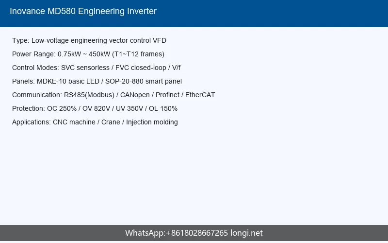
The MD580 series supports two types of operation panels to accommodate different operational requirements: the MDKE-10 LED operation keypad and the SOP-20-880 intelligent operation keypad. Both panels serve as the primary human-machine interface for parameter configuration, status monitoring, and local control operations.
2.1 MDKE-10 LED Operation Panel
The MDKE-10 is the standard LED-based operation panel supplied with the MD580 series. This panel features a bright LED display capable of showing operational parameters, fault codes, and status indicators. The panel layout includes navigation keys for parameter browsing, a numeric keypad for direct value entry, and function keys for quick access to commonly used operations.
Key functions of the MDKE-10 panel include parameter viewing and modification, system time configuration, and direct motor control for commissioning purposes. The panel enables operators to navigate through the extensive parameter set organized by functional groups, read real-time connector values (monitoring parameters), and execute commands such as start, stop, and direction reversal when local control is activated.
The LED panel supports password-protected parameter access. For basic parameter modification, users must navigate to the target parameter address and enter the appropriate value. The panel displays the parameter group (designated by letter codes: A for system parameters, b for control channels, C for setpoint channels, d for motor parameters, E for motor control, F for input/output, H for faults and protection, L for application functions, and n for bus adapters and expansion modules) followed by the specific parameter number.
2.2 SOP-20-880 Intelligent Operation Panel
The SOP-20-880 is an optional intelligent panel featuring an LCD display with Chinese and English bilingual prompts. This panel significantly enhances usability by providing descriptive text for parameters and operations, reducing the learning curve for technicians. The LCD panel supports parameter copy functionality, enabling rapid replication of drive configurations across multiple units, a feature particularly valuable when commissioning production lines with identical drive requirements.
Both panels incorporate status indicators that communicate the operational state of the inverter. Typical indicators include RUN (operation status), FWD/REV (direction), and fault indicators. The panels also facilitate relay connections to PC systems for extended monitoring and parameter management through the InoDriveStudio software platform.
2.3 Parameter Navigation and Editing
Parameter access follows a structured hierarchy. Users press the programming key to enter parameter mode, then use navigation keys to select parameter groups and individual parameters. When editing a parameter, the current value is displayed and can be modified using the numeric keys or increment/decrement buttons. Parameter changes are typically stored in volatile memory and must be explicitly saved to non-volatile memory to persist through power cycles.
For quick motor demonstration and commissioning, the operation panels provide a drive motor demonstration mode that allows basic operation verification without full parameter configuration. This mode is particularly useful during initial installation to confirm wiring correctness and basic functionality before proceeding to application-specific tuning.
3. Terminal Control and Wiring
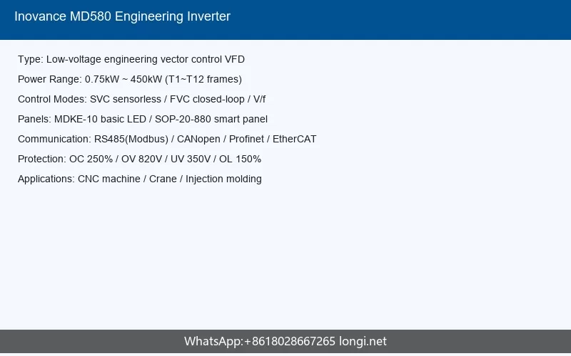
The MD580 series provides comprehensive terminal control capabilities through its main circuit terminals and control circuit terminals. Proper terminal wiring is critical for safe operation, electromagnetic compatibility, and reliable performance.
3.1 Main Circuit Terminals
The main circuit terminals handle power input (R, S, T for three-phase AC input) and motor output (U, V, W). Depending on the structural class, main circuit terminals vary in size and connection type. T1 through T4 structures feature built-in braking units as standard, while T5 through T8 offer optional braking unit configurations. T5 and above include standard DC reactors for harmonic suppression. The output voltage ranges from 0 to input voltage, with maximum output frequency configurable up to 599 Hz.
Main circuit wiring requirements emphasize proper cable sizing, secure terminal connections with specified tightening torques, and appropriate cable routing to minimize electromagnetic interference. The installation manual specifies detailed cable selection criteria based on rated current, with different requirements for power cables connecting to input terminals and motor output terminals. Terminal lugs must be selected according to the cross-sectional area of the cables being used.
3.2 Control Circuit Terminals
The control circuit terminals provide the interface for digital inputs (DI), digital outputs (DO), analog inputs (AI), analog outputs (AO), high-speed digital inputs (HDI), and high-speed digital outputs (HDO). These terminals enable the inverter to receive commands from external control systems, provide status feedback, and interface with process control equipment.
Digital inputs support multiple start/stop modes through the terminal start/stop module, offering six predefined terminal control patterns. These modes accommodate various industry-standard control schemes including two-wire and three-wire control configurations. Digital outputs include relay outputs (RO) that can be configured to indicate specific operational states or fault conditions.
Analog inputs accept 0-10V or 4-20mA signals for speed reference, torque reference, or process variable feedback in PID control applications. Analog outputs can be programmed to represent operational parameters such as output frequency, output current, or DC bus voltage for external monitoring instrumentation. High-speed inputs support pulse train signals for precise speed reference or position feedback applications.
3.3 Wiring Best Practices
The installation documentation emphasizes several critical wiring practices. Control circuit wiring should utilize shielded twisted-pair cables with the shield connected to the inverter’s grounding terminal to prevent operational anomalies. Signal cables must be separated from power cables by a minimum distance of 30 cm to reduce coupling of high-frequency noise. For high-speed pulse signals, shielded cables with both ends grounded are recommended, and ferrite cores or magnetic rings should be applied to signal lines with 1-2 turns.
Grounding requirements are extensive and include main circuit grounding, control board grounding, and system grounding for multi-drive installations. The PE terminal must be reliably connected to the system protective earth conductor. For single-device installations, the grounding impedance must meet local electrical codes. Cabinet installations require the complete system enclosure to be bonded to the facility ground grid.
STO (Safe Torque Off) safety functionality requires dedicated wiring following safety design guidelines. The STO circuit provides a hardware-level safety shutdown that directly inhibits IGBT gate drive signals, independent of the control processor.
4. Parameter Initialization and Password Management
4.1 Parameter Backup and Restoration
The MD580 series offers robust parameter management capabilities essential for maintenance, replacement, and system standardization. The drive supports multiple methods for parameter backup and restoration, ensuring that optimized configurations can be preserved and replicated.
Factory parameter restoration can be executed through the operation panel or PC software. The system provides three restoration modes: complete factory reset (restoring all parameters to default values), partial reset preserving motor parameters (useful when replacing a drive while retaining tuned motor data), and fault record clearing. Additionally, time statistics can be reset independently.
Internal memory backup allows parameter sets to be stored within the inverter’s non-volatile memory. The SOP-20-880 intelligent panel supports file-based parameter backup, where complete parameter sets can be saved to the panel’s internal storage and subsequently restored to the same or different drives. This feature dramatically reduces commissioning time in multi-drive applications.
PC-based parameter management through InoDriveStudio provides the most comprehensive backup capabilities. The software enables users to create project files containing complete drive configurations, perform parameter comparisons between current values and backup files, download parameters to drives, and organize parameters into custom groups for efficient management. The software also supports search functionality to quickly locate specific parameters within the extensive parameter set.
4.2 Password and Access Control
Parameter security is implemented through password protection mechanisms. Basic parameter modification requires operator-level access, while advanced parameters controlling motor control algorithms, protection thresholds, and communication configurations may require higher privilege levels. Password management prevents unauthorized modifications that could compromise system safety or operational performance.
The parameter structure organizes functionality into major groups. Group A contains system parameters including inverter configuration and basic operating modes. Group b covers control channel settings defining how start/stop commands and speed references are sourced. Group C manages setpoint channel parameters for speed, torque, and multi-speed configurations. Group d stores motor nameplate data and auto-tuned parameters. Group E configures motor control strategies including vector control and V/f control parameters. Group F defines input/output terminal functions. Group H establishes fault detection thresholds and protection behavior. Group L contains application-specific functions such as PID control, sleep/wake functions, and anti-power-fluctuation settings. Group n configures fieldbus adapters and expansion modules.
4.3 Commissioning Parameters
Commissioning begins with setting the load mode (P-type for light overload or G-type for heavy overload), which determines the overload curve and thermal protection characteristics. Motor basic parameters including rated power, rated voltage, rated current, rated frequency, and rated speed must be accurately entered from the motor nameplate. The control method (SVC, FVC, or V/f) is selected based on application requirements and encoder availability.
Encoder configuration parameters support incremental encoders, resolvers, and other feedback devices. The system provides hardware wire-break detection for incremental encoders and resolvers, with configurable software-based break detection settings. Pulse count configuration and encoder angle simulation parameters enable precise speed and position feedback processing.
Motor parameter auto-calculation and motor identification (auto-tuning) procedures allow the drive to measure and optimize motor electrical characteristics. Before executing motor identification, operators must verify that the motor is uncoupled from mechanical loads, that wiring is correct, and that no personnel are in the vicinity of rotating machinery. The identification process measures stator resistance, inductance, and flux characteristics to optimize control performance.
5. Common Fault Codes and Troubleshooting
5.1 Fault Classification and Viewing
The MD580 series implements a hierarchical fault management system that classifies anomalies by severity level. Faults are categorized into distinct classes that determine the response behavior, including whether the drive trips immediately, provides a warning while continuing operation, or logs an event for later review. The fault classification system enables application-specific customization of protection sensitivity.
Fault information can be viewed through the operation panel display, the InoDriveStudio software, or via communication networks. The fault viewing interface presents the active fault code, fault description, and supplementary diagnostic information including the operational state at the time the fault occurred. Historical fault records are maintained in a log that can be reviewed to identify recurring issues or patterns.
Fault reset methods include automatic reset (configurable for certain fault types with programmable delay times), manual reset via the operation panel, digital input reset commands, and communication-based reset instructions. The automatic reset function can be enabled for specific fault classes, with configurable retry counts and intervals, though this feature must be applied cautiously in applications where unexpected restart could create safety hazards.
5.2 Common Fault Conditions
Overcurrent faults represent one of the most common protection events. The drive monitors output current continuously and triggers protection when current exceeds 2.5 times the rated value. The instantaneous overcurrent threshold is set at 250% of rated output current. Overcurrent conditions may result from sudden load changes, mechanical jamming, incorrect motor parameters, or excessively aggressive acceleration profiles. Troubleshooting overcurrent faults involves verifying load mechanics, checking acceleration/deceleration time settings, confirming motor parameter accuracy, and inspecting for short circuits or ground faults in motor cables.
Overvoltage faults occur when the DC bus voltage exceeds 820V, typically during regenerative braking with high-inertia loads or when deceleration times are too short for the braking unit to dissipate energy. Solutions include extending deceleration ramps, verifying braking resistor functionality, or enabling VDC voltage control functions that manage regenerative energy. Undervoltage protection triggers when the DC bus falls below 350V, indicating insufficient input voltage, phase loss, or pre-charge circuit malfunction.
Motor overload protection operates based on thermal models that simulate motor heating. P-type mode allows 110% rated current for 60 seconds before tripping, while G-type mode permits 150% for 60 seconds. Persistent overload conditions require evaluation of load requirements versus drive and motor ratings. Motor stall protection detects conditions where the motor cannot accelerate or maintain speed against excessive load torque.
Pre-charge faults indicate failure of the DC bus capacitor charging circuit during power-up. This condition requires inspection of the charging resistor, contactor operation, and DC bus voltage sensing circuits. Parameter setting errors can also trigger protection when incompatible values are configured; the fault viewing interface typically identifies the parameter group requiring attention.
5.3 EMC-Related Issues
Electromagnetic compatibility problems manifest in various forms including leakage current causing protective device trips, control signal interference, and communication errors. The MD580 installation guide provides systematic remediation procedures.
Leakage current exceeding 100mA per drive requires selection of B-type (time-delayed) residual current devices with ratings above 100mA. For multiple-drive installations, each inverter should have individual RCD protection. Mitigation strategies include reducing carrier frequency, shortening motor cable lengths, installing leakage suppression devices, and using recommended RCD brands from manufacturers such as Chint or Schneider.
Control circuit interference affecting high-speed pulse signals or general I/O can be addressed by using shielded twisted-pair cables with shields connected to PE terminals, maintaining minimum 30cm separation between signal and power cables, applying ferrite cores to affected lines, and ensuring motor housings are bonded to the inverter PE terminal. Communication interference on RS-485 or CAN networks requires termination resistors at bus ends, shielded multi-conductor twisted-pair cabling, daisy-chain topology for multi-node networks, and ferrite cores on communication cables.
Encoder feedback errors often result from improper cable routing. Remediation steps include routing encoder cables in separate conduits from motor power cables, disconnecting encoder shield grounds at the motor end for long cable runs (exceeding 10m), installing ferrite cores near the inverter end of encoder cables, and applying magnetic rings to inverter output cables.
5.4 Preventive Maintenance
Regular maintenance extends drive reliability and prevents unexpected failures. The manufacturer recommends periodic inspection of cooling fans, which have finite operational life and require replacement when bearing wear or reduced airflow is detected. Fan replacement intervals depend on operating conditions but should be evaluated during scheduled maintenance windows. Capacitor aging affects DC bus filtering performance; drives stored for extended periods require reconditioning by gradual voltage application for minimum five hours within six-month intervals.
Terminal tightness should be verified periodically, as thermal cycling can loosen connections and create overheating hazards. Cleaning of heatsinks and ventilation paths prevents thermal derating and overtemperature faults. Environmental conditions must be monitored to ensure continued compliance with the specified operating ranges for temperature, humidity, and contamination levels.
6. Conclusion
The Inovance MD580 series low-voltage engineering inverter represents a comprehensive solution for industrial motor control applications requiring precision, reliability, and flexibility. With its support for both permanent magnet synchronous and asynchronous induction motors, advanced vector control algorithms, and extensive communication capabilities, the series addresses the diverse requirements of modern manufacturing, material handling, and process control systems.
Successful implementation of the MD580 series depends on thorough attention to installation practices, particularly in the areas of grounding, shielding, and cable management that directly impact electromagnetic compatibility and operational stability. The dual operation panel options accommodate different user preferences and application complexity levels, from the straightforward LED panel for basic operation to the intelligent LCD panel with bilingual support for sophisticated parameter management.
The robust parameter architecture, combined with comprehensive backup and restoration capabilities, enables efficient deployment and maintenance of multi-drive systems. The hierarchical fault management system, supported by detailed troubleshooting guidance, helps minimize downtime and directs maintenance personnel toward effective remediation actions. By following the documented wiring practices, respecting environmental specifications, and implementing recommended EMC mitigation measures, engineers can achieve optimal performance and long-term reliability from the MD580 series drives.
As industrial automation continues to evolve toward higher efficiency and tighter process integration, the MD580 series provides the technical foundation for demanding applications while maintaining the accessibility and serviceability characteristics essential for sustainable operation in production environments. Users are encouraged to consult the complete documentation set including the hardware manual, communication manual, and function manual for detailed specifications relevant to their specific application requirements.