Posted on

GSK980TD CNC System Manual Guide: Operation Panel, Parameter Switch, PLC Diagnosis, Homing, MDI, Tool Offset, I/O and Fault Repair

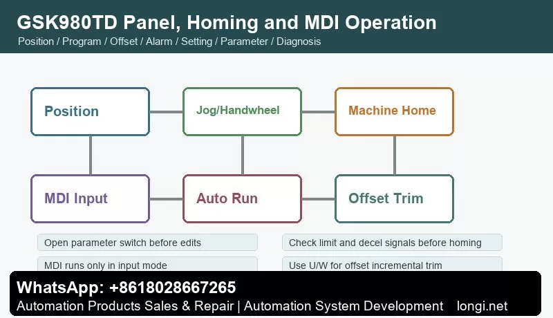
GSK980TD CNC panel homing and MDI operation flow

GSK980TD CNC System Manual Guide: Operation Panel, Parameter Switch, PLC Diagnosis, Homing, MDI, Tool Offset, I/O and Fault Repair

What the GSK980TD Controls

GSK980TD CNC panel homing and MDI operation flow

GSK980TD is a lathe CNC system used on economical CNC lathes and retrofit machines. It is not only a display unit or a servo drive. It interprets machining programs, controls X/Z axis motion, handles spindle, coolant, lubrication and turret M functions, manages I/O logic, tool offsets, alarms and machine parameters.

For maintenance, judge the system as a complete chain: operation mode, parameter switch, PLC inputs and outputs, axis drive, limit switches, emergency stop, spindle control and program state. A screen without an alarm does not mean the machine is ready, and a ready servo drive does not mean the CNC conditions are satisfied.

Panel and Page Functions

The operation panel has LCD display, edit keyboard, page keys and machine-control keys. Page keys include Position, Program, Offset, Alarm, Setting, Parameter and Diagnosis. Mode keys include Edit, Auto, MDI Input, Manual, Handwheel/Step, Program Zero Return and Machine Zero Return.

The practical diagnostic order is: check Alarm page, check Diagnosis page for I/O, confirm key parameters, observe axis status on Position page, then use Manual or MDI for low-risk movement. Direct cycle start before checking these pages can turn a simple limit or offset issue into a crash.

Parameter Switch, Password and Electronic Disk
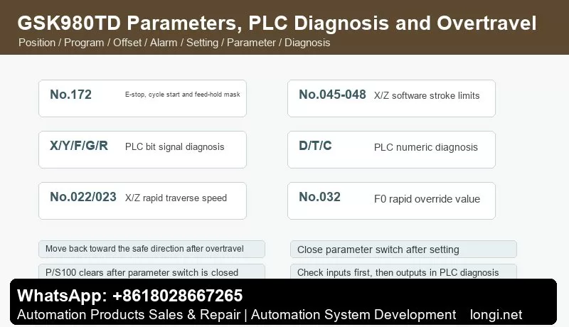
GSK980TD parameters PLC diagnosis and overtravel handling

The Setting page includes parameter switch and program switch. When the parameter switch is off, system parameters cannot be modified. When it is turned on, P/S100 may appear. After setting parameters, turn the switch off again; the alarm normally clears or can be reset. Always close the parameter switch after service.

GSK980TD uses multiple password levels: system debugging, system configuration, machine builder, workshop management and operator. Low-level users cannot edit protected O9000-O9999 programs. Use the password page when protected parameters or builder programs must be modified.

The electronic disk stores state parameters, data parameters, pitch compensation and tool offsets. N0 stores factory original data, N2 servo original data, N3 stepper original data, N4 common data and N1 user data. Before large adjustments, back up working parameters to N1 or to a PC.

I/O and PLC Diagnosis

The Diagnosis page shows keyboard diagnosis, status diagnosis, PLC signal status and PLC numeric diagnosis. PLC bit signals include X0000-X0029, Y0000-Y0019, F0000-F0255, G0000-G0255, A0000-A0024, K0000-K0039 and R0000-R0999. Numeric diagnosis includes D0000-D0999, T0000-T0099 and C0000-C0099.

Use the rule: input before output, safety chain before action chain, diagnosis before rewiring. If cycle start fails, check emergency stop, feed hold, auto mode, program selection and cycle-start input first. If coolant does not work, check the internal PLC signal before checking relay output. If turret does not index, check output, in-position input and turret power.

Emergency stop can be masked by state parameter No.172 Bit3 (MESP), and external E-stop can be checked by diagnostic No.001 Bit4 (*ESP). Do not leave E-stop or limit switches bypassed after testing.

Manual, Handwheel and Homing

Manual mode supports X/Z jogging, rapid traverse, spindle control, coolant, lubrication and turret operation. Data parameters No.022 and No.023 set X/Z rapid speeds. No.032 sets the F0 rapid override. After repair, use low rapid override first and verify direction, limit switches and mechanical clearance.

Handwheel/step mode is selected by state parameter No.001 Bit3. Select X or Z axis and choose handwheel magnification. The manual warns that handwheel rotation should be below 5 revolutions per second; otherwise actual movement may not match scale marks.

Zero return includes program zero return and machine zero return. Machine zero return depends on the installed deceleration switch, one-revolution signal or Hall switch. If the machine has no reference switch, do not use machine zero return. Check return direction, decel switch, limit switch, servo ready and E-stop before homing.

MDI and Automatic Run

MDI can run one command block, such as G50, G00, G01, M03, M05, M08, M09, S and T commands. MDI runs only in input mode. Use it to test spindle, coolant, turret and short low-speed movement, but do not treat MDI as a full replacement for dry run and single-block verification.

Before automatic running, confirm the program, current coordinate, work offset, tool offset, spindle state and modal G/M/S/T conditions. When starting from a middle block, use MDI to restore required modal states first.

Tool Offset and Tool Setting

The Offset page modifies X/Z offset values. Absolute input uses X or Z. Incremental trim uses U or W. For example, input U0.001 to increase X offset by 0.001 mm. When the origin of an offset is unclear, avoid rewriting absolute X/Z values; use small U/W trims and record before/after values.

GSK980TD supports fixed-point tool setting, trial-cut tool setting, machine-zero tool setting and tool setting with compensation. Tool setting with compensation requires state parameter No.005 Bit1 (PPD). Direct measured offset input depends on state parameter No.012 Bit5 (DOFSI).

Common G Codes and Auxiliary Functions

Common lathe commands include G00 rapid positioning, G01 linear interpolation and G50 coordinate setting. Common M functions include M03 spindle forward, M04 spindle reverse, M05 spindle stop, M08 coolant on and M09 coolant off. Actual spindle speed display requires a spindle encoder.

If M03 is issued but the spindle does not rotate, separate CNC M-output, spindle inverter/servo enable, analog command, forward/reverse terminals and spindle override. If only speed display is missing, check spindle encoder feedback and related parameters.

Overtravel and Safety Alarms

GSK980TD uses hardware overtravel switches and software stroke limits. Software travel range is set by data parameters No.045, No.046, No.047 and No.048 for X/Z positive and negative limits. After overtravel, move manually toward the safe direction, then press reset. Do not permanently disable software limits or short hardware limit switches.

After E-stop release, spindle, coolant and lubrication usually need to be restarted. If axes still cannot move, check not-ready alarm, *ESP signal, servo ready, limit state and selected operation mode.

Fault Handling Checklist

P/S100 alarm: usually related to open parameter switch. Close the switch, reset and power cycle if necessary.

Cycle start invalid: check auto mode, selected program, E-stop, feed hold, cycle-start input and PLC condition.

Axis does not move or direction is wrong: check mode, servo ready, enable, limits, homing status, direction parameters, servo alarm and command output.

Machine zero return fails: check homing mode, return direction, decel switch, one-revolution signal, limit switch, No.113 homing rapid speed and No.033 FL speed.

Tool offset ineffective or size error: check offset number, T command, X/Z versus U/W input, work coordinate, machine zero return, backlash and pitch compensation.

Spindle does not rotate or speed is wrong: check M03/M04/M05 output, spindle override, analog or switch speed mode, spindle encoder and inverter or spindle servo parameters.

Coolant, lubrication or turret does not work: check PLC internal signal, Y output, relay, fuse, contactor and load. For turret faults, also check in-position signal and tool-number feedback.

The most reliable workflow is: use Alarm page to classify the fault, Diagnosis page to verify signals, Parameter page to check configuration, Manual/MDI to test safely, then Auto mode for final dry run and cutting verification.
Posted on

GSK DA98 AC Servo Drive Manual Guide: CN1/CN2 Wiring, Position Pulse Control, Speed Control, Electronic Gear Ratio, EEPROM Write and Alarm Repair

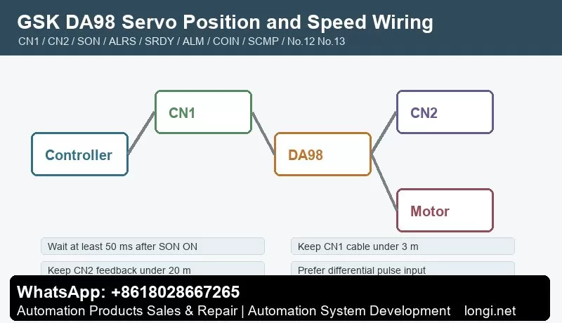
GSK DA98 servo CN1 CN2 position and speed control wiring

GSK DA98 AC Servo Drive Manual Guide: CN1/CN2 Wiring, Position Pulse Control, Speed Control, Electronic Gear Ratio, EEPROM Write and Alarm Repair

DA98 Is a Classic Digital AC Servo for CNC Retrofits

GSK DA98 servo CN1 CN2 position and speed control wiring

GSK DA98 is an early full-digital AC servo drive widely used on CNC machines, printing machinery, textile machinery and automation lines. Compared with a stepper system, DA98 uses encoder feedback from the servo motor and forms a semi-closed loop inside the drive.

For service work, do not only ask whether the motor rotates. Check control mode, CN1 command signals, CN2 encoder feedback, electronic gear ratio, gains and alarm output together. In position mode the CNC sends pulse and direction; in speed mode DA98 uses speed selection or speed command; in both modes SON enable and encoder feedback are essential.

Installation and Wiring Checks

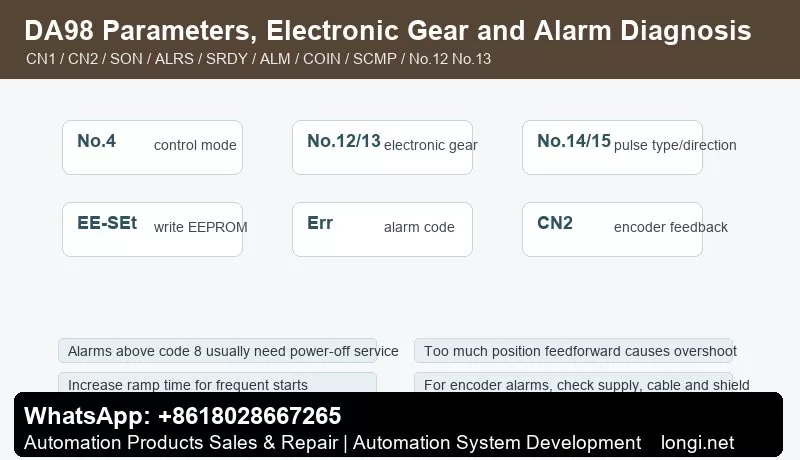
GSK DA98 parameters electronic gear and alarm diagnosis

The manual notes that DA98 default parameters may match only specific STZ motors. If another motor is used, factory parameters may be stored in the EEPROM backup area. Do not restore default parameters blindly. Confirm drive model, motor model and parameter No.1 first.

Before wiring or inspection, cut power and wait at least five minutes. Use proper grounding. Keep CN1 control cable under 3 m and CN2 feedback cable under 20 m. Use shielded cable, connect shield to FG and keep signal cables away from motor power cable, contactor coils and braking circuits.

CN1 Control Signals

CN1 includes COM+, SON servo enable, ALRS alarm reset, FSTP/RSTP drive inhibit, CLE deviation counter clear, SC1/SC2 internal speed selection, INH pulse inhibit, FIL/RIL torque limit, SRDY servo ready, ALM servo alarm, COIN in-position, SCMP speed arrival, PULS/SIGN command pulse and encoder Z output.

Commission in layers. First power, motor and encoder. Then enable SON and wait at least 50 ms before command input. Then connect SRDY and ALM to CNC or PLC. Finally test PULS/SIGN, COIN, SCMP, limits and torque-limit inputs. ALRS cannot clear all alarms; alarms above code 8 normally require power-off service.

CN2 Encoder Feedback

CN2 carries motor encoder supply and A/B/Z/U/V/W signals. The manual describes a 2500-line encoder, internally multiplied to 10000 pulses per revolution. Encoder supply, shield, pin order and cable length strongly affect stability.

For encoder alarms, do not change gains first. Check 5 V supply, cable length, A/B/Z/U/V/W wiring, shield and connector. Z-pulse loss, UVW error, encoder count error and zero-point error usually point to cable, connector, encoder or drive-interface problems.

Position Pulse Control

DA98 accepts position command pulses through CN1. Supported pulse formats include pulse plus direction, CCW/CW pulse train and two-phase quadrature pulse. Parameter No.14 sets pulse input format and No.15 reverses command direction. Differential pulse input is preferred; single-ended input lowers noise immunity and allowable frequency.

If axis direction is wrong, decide whether the cause is CNC direction, No.15, motor phase or mechanics. Do not change several places at once. If the axis does not respond, check INH, SON, FSTP/RSTP, ALM and whether PULS/SIGN actually reaches CN1.

Electronic Gear Ratio: No.12 and No.13

No.12 is the position command pulse division numerator. No.13 is the denominator. Together they define the electronic gear ratio. Because a 2500-line encoder becomes 10000 feedback pulses per revolution after four-times counting, the ratio must account for encoder pulses, screw pitch, reduction ratio and CNC pulses per millimeter.

Proportional size error usually means electronic gear error. Bidirectional repeatability error points more to backlash, coupling, encoder feedback or gain setting.

Speed Mode and Internal Speeds

Set No.4 to speed mode when DA98 is used as a speed servo. Internal speeds are selected through SC1/SC2 and parameters such as No.24-No.27. SCMP speed-arrival output can be used by PLC. JOG speed is set by No.21 and is useful for no-load testing.

If speed mode does not run, check No.4, SON, ALM, SC1/SC2, speed parameters, FSTP/RSTP, torque limit and maximum speed No.23. If no-load operation is normal but load operation alarms, check load inertia, ramp time No.7 and torque limits No.34-No.37.

Gain Tuning

Tune speed loop first, then position loop. Higher speed proportional gain improves stiffness but can cause vibration. Higher position proportional gain reduces following error but can cause overshoot. Position feedforward is normally set to zero unless high response is required; excessive feedforward can destabilize the position loop.

Frequent starts, large inertia and short ramp time can cause overheating or overvoltage. Start with conservative ramp time, then improve response gradually.

EEPROM Parameter Write

Parameter edits are in memory until written. EE-SEt writes memory parameters into EEPROM. Select EE-SEt, press and hold Enter for more than three seconds, wait for StArt and then FInISH. EE-dEF restores defaults, but use it only after confirming drive model No.1.

Before delivery, record No.1, No.4, No.7, No.9, No.10, No.12, No.13, No.14, No.15, No.20, No.21, No.23 and No.34-No.37.

Alarm Diagnosis

Main-circuit overvoltage: usually caused by fast deceleration, high inertia, braking problem or power abnormality. Increase No.7 and check load.

Encoder faults: check CN2 supply, cable, shield, pin order, encoder and interface circuit. Long cable can reduce encoder supply voltage.

Following error: check electronic gear ratio, pulse frequency, position gain and mechanical jam. Do not only enlarge the error window.

Vibration with alarm: check coupling, inertia, speed gain, position gain and encoder cable before replacing the drive.

Reset invalid: alarms above code 8 usually cannot be cleared only by ALRS; power-off inspection is required.

The reliable DA98 workflow is: confirm motor and drive model, wire TB/CN1/CN2, set No.4 mode, calculate No.12/No.13 electronic gear, run no-load JOG, test low-speed pulse motion, tune speed and position loop, execute EE-SEt, then verify under load.

Posted on

Huazhong CNC HNC-210A/HNC-210B Manual Guide: Operator Panel, I/O Wiring, Servo and Spindle Connection, PLC Addresses, G-Code Interlocks and Fault Diagnosis

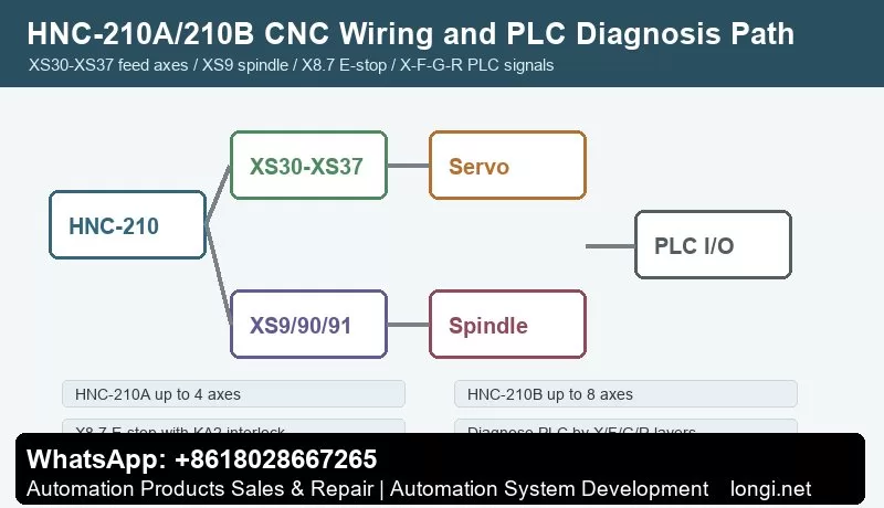
Huazhong CNC HNC-210A HNC-210B wiring and PLC diagnosis path

Huazhong CNC HNC-210A/HNC-210B Manual Guide: Operator Panel, I/O Wiring, Servo and Spindle Connection, PLC Addresses, G-Code Interlocks and Fault Diagnosis

HNC-210 Commissioning Is About the Whole Machine Link

Huazhong CNC HNC-210A HNC-210B wiring and PLC diagnosis path

HNC-210 is an open-architecture CNC unit with an industrial PC, 32-bit processor, feed-axis interfaces, spindle interface, handheld unit interface, embedded PLC and Ethernet expansion. HNC-210A supports up to four pulse axes. HNC-210B supports up to eight pulse axes.

For retrofit and repair work, the key is not one menu or one parameter. The real system is made from CNC, servo drives, spindle drive, I/O terminal boards, emergency stop circuit, overtravel circuit and PLC ladder logic. Wiring tells where the signal goes; PLC logic tells why the machine allows or blocks motion. Both must be checked together.

Panel and Handheld Unit

The machine operation panel and handheld unit provide mode selection, axis selection, override, emergency stop, cycle start, feed hold and handwheel jog. Before changing parameters, check mode, E-stop state, feed override, spindle override, handheld connection and panel indicators.

The manual explains that E-stop buttons on the panel and handheld unit are wired into the safety circuit. Additional E-stop buttons may be added. Their normally closed contacts should be connected in series. When any E-stop is pressed, relay KA2 drops out, cutting power or enable to feed axes, spindle, tool changer or turret, while an auxiliary contact feeds the PLC alarm input.

Digital I/O and Terminal Boards

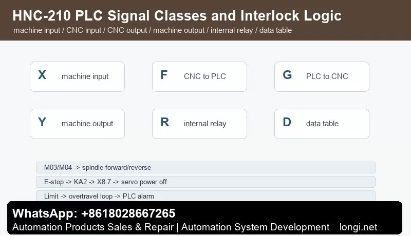
HNC-210 PLC signal classes and E-stop spindle interlocks

HNC-210 can use digital input/output interfaces and terminal boards. Typical ranges include X0.0-X7.3 inputs and Y0.0-Y5.7 outputs, plus handheld inputs X8.0-X8.6, E-stop X8.7 and handheld outputs Y6.0-Y6.3.

Diagnose I/O in this order: field switch, terminal LED, CNC input address, PLC logic, CNC output address, relay or solenoid. Measuring 24 V on a wire is not enough; the CNC diagnosis page must show that the address changed.

Feed-Axis Servo Connection Through XS30-XS37

HNC-210A provides up to four pulse-axis connectors XS30-XS33. HNC-210B/C provides up to eight connectors XS30-XS37. Each axis outputs command pulse CP+/CP- and direction DIR+/DIR- to a servo or stepper drive, with related ready or mode signals.

With pulse-interface servo drives, the position loop is usually inside the servo drive. HNC-210 sends command pulses. Full closed-loop control requires a suitable servo drive with full-closed-loop feedback. Electronic gear ratio, servo gain, alarm output and in-position signals are still configured in the servo drive.

Spindle Interfaces XS9, XS90 and XS91

The spindle side includes XS9 SPDL.0, XS90 SPDL.1 encoder and XS91 SPDL1 I/O. Common signals include X3.0 alarm input, X3.1 speed arrival, X3.2 zero-speed arrival, X3.3 orientation complete, Y1.0 forward, Y1.1 reverse, Y1.2 enable, Y1.3 orientation, AOUT1 -10 V to +10 V and AOUT2 0 V to +10 V.

For inverter spindles, check analog speed output, forward/reverse outputs, enable, alarm input and speed arrival. For servo spindles, also check orientation complete, zero speed and encoder feedback. Threading and rigid tapping require correct spindle encoder feedback.

E-Stop and Overtravel

X8.7 is the E-stop input. KA2 is used for power/enable interlock of servo and spindle circuits. Y0.7 is shown in the manual example as overtravel release output. Overtravel limit switches use normally closed contacts in the overtravel chain and normally open contacts into PLC inputs so the system can identify the axis and direction.

Do not bypass E-stop or limit circuits just to clear an alarm. Check X8.7, limit input addresses, KA2 coil, KA2 auxiliary contact, Y0.7 output and the PLC alarm bit to determine whether the problem is the safety chain, PLC condition or servo alarm.

PLC Signal Classes: X/F/G/Y/R/D

The PLC programming manual separates machine inputs, CNC-to-PLC signals, PLC-to-CNC signals, machine outputs, internal relays and data tables. A practical way to read the ladder is X/F/G/Y/R/D: X for field inputs, Y for field outputs, F for CNC-to-PLC system signals, G for PLC-to-CNC status/control, R for internal relays and D/data table for stored states such as tool data.

For M03, CNC sends a spindle-forward request to PLC. PLC checks E-stop, alarm, lubrication, clamp, spindle-drive ready and door interlock. If conditions are satisfied, it outputs Y1.0 and Y1.2 and waits for X3.1 speed arrival. An M code is not just one output bit; it is a request filtered by the PLC safety chain.

Simple G-Code Interlock Example

“`gcode

M03 S800

G04 X2.0

G01 X50.0 F100

M05

“`

Behind this short program, the PLC must enable spindle forward, send analog speed reference, wait for speed arrival, allow feed, stop spindle output and confirm zero speed or braking. If the program stops after M03, check speed arrival, alarm input, enable output and the PLC waiting condition.

Fault Diagnosis

Axis does not move: check X8.7, KA2, servo ready, XS30-XS37, CP/DIR output, axis parameters and drive alarms.

Spindle does not run: check M03/M04 request, Y1.0/Y1.1/Y1.2, AOUT1/AOUT2, X3.0 alarm, X3.1 speed arrival, spindle-drive enable and analog common.

Homing direction is wrong: check axis direction parameter, drive direction, home switch address, limit state, homing mode and PLC permission.

E-stop cannot reset: check all E-stop NC contacts, KA2 coil, KA2 auxiliary contact, X8.7 diagnosis and PLC reset conditions.

Overtravel release does not work: check limit NC chain, limit feedback, Y0.7 output, overtravel-release button, reverse jog direction and PLC latch.

Tool changer loses tool number: check tool-position switches, spindle clamp/unclamp, tool data table, current spindle tool number, internal relays and power-loss recovery logic.

The practical rule for HNC-210A/HNC-210B is: confirm hardware by connector, confirm I/O by X/Y addresses, read PLC logic by F/G/R/D layers, then verify the motion chain with short G-code tests.

Posted on

GSK GS3000Y and GS4000Y AC Spindle Servo Unit Manual Guide: Panel Operation, CN1/CN2/CN3 Wiring, Parameter Management, Spindle Orientation, Cs Axis and Fault Diagnosis

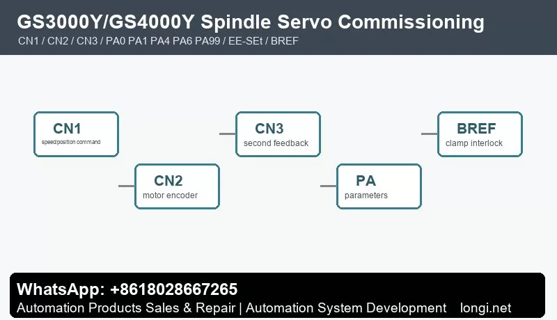
GSK GS3000Y GS4000Y spindle servo CN1 CN2 CN3 commissioning framework

GSK GS3000Y and GS4000Y AC Spindle Servo Unit Manual Guide: Panel Operation, CN1/CN2/CN3 Wiring, Parameter Management, Spindle Orientation, Cs Axis and Fault Diagnosis

Treat GS3000Y/GS4000Y as a Spindle Process Unit

GSK GS3000Y GS4000Y spindle servo CN1 CN2 CN3 commissioning framework

GSK GS3000Y and GS4000Y AC spindle servo units are used on CNC lathes, machining centers and automation equipment. They support constant-power speed control, spindle orientation and Cs-axis position control. They should not be commissioned like ordinary inverters.

A spindle servo system must coordinate speed, position feedback, braking, orientation, clamp interlock and CNC machining sequence. M03 requires speed arrival before feed; tool change requires orientation; rigid tapping or Cs-axis control requires position mode; chuck and tool-clamp signals must be part of PLC interlocks. Commission the unit in the order of wiring, feedback, parameter management, speed operation, orientation/Cs axis and fault diagnosis.

Model and Interface: GS-N Versus GS-C

The manual separates GS-N and GS-C types. GS-N uses D-SUB connectors, usually with incremental encoder motors and no GSK-CAN bus. GS-C uses MDR connectors, supports absolute encoder motors and includes GSK-CAN. Feedback codes are also important: P is for incremental encoder, A/B for absolute encoder, 1 for CN2 motor feedback only, and 2 for both CN2 motor feedback and CN3 second feedback.

When replacing a drive, do not check only power rating. Confirm voltage class, output current, motor type, encoder type, CN2/CN3 configuration, second-feedback requirement and CNC interface. A mismatched encoder interface can power on normally but fail in orientation or position control.

Power Wiring, Brake Resistor and Safety

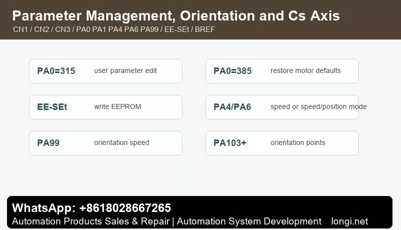
GSK GS3000Y GS4000Y parameter management spindle orientation and Cs axis

Install proper breaker, contactor, grounding, shield treatment, reactors or filters as required. Check input power, U/V/W motor output, brake resistor, PE grounding and cable shielding. If Err-27 appears during running, the manual points to checking motor phase sequence and swapping two phases where appropriate.

Brake resistors can remain hot and charged after operation. Wait before touching. Frequent spindle acceleration and deceleration requires correct braking capacity. Undersized or open brake resistor can cause overvoltage, long stopping distance or repeated alarms.

Panel and Status Monitoring

The panel uses keys for parameter number, value editing, shift and confirmation. The manual notes that the decimal point on the display indicates whether an edited parameter has been confirmed. If you exit without confirmation, the setting is invalid.

Menus include status monitoring, parameter setting, parameter management, manual run and jog run. PA3 selects the initial monitor state. Useful monitor items include motor speed, current position, position command, following error, motor current, analog speed command, speed command, pulse command frequency, torque, heatsink temperature, motor temperature, DC bus voltage, alarm display, input status and output status.

PA0, PA1 and EEPROM Parameter Management

The manual clearly states that PA0=315 is the user parameter modification password. At each power-on, PA0 returns to 315. PA0=385 is used to restore motor default parameters and allows PA1/PA2 editing. PA1 is the motor model code.

EE-SEt writes memory parameters into the EEPROM parameter area. EE-rd reads EEPROM parameters back into memory. EE-bA writes current parameters into the backup area. If a parameter works today but disappears after power cycling, EE-SEt was probably not executed. After final commissioning, execute EE-SEt, then use EE-bA for backup and verify after power cycling.

CN1 Control Signals

CN1 carries the key interface between CNC and spindle servo: analog speed command, pulse position command, enable, forward/reverse, reset, orientation start, clamp interlock, speed arrival, zero speed, alarm output and position output.

Wire and test in layers. First power and encoder, then enable and alarm output, then speed command and direction, then orientation, speed arrival, zero speed, BREF clamp interlock and position outputs. Do not wire every CN1 signal at once during retrofit; otherwise command faults, feedback faults and PLC interlocks are hard to separate.

The manual appendix gives examples for GSK980TDc and GSK988T. For speed control with orientation, typical settings include PA4=1, PA6=1 for external 0-10 V analog command, PA51 for analog-speed direction reversal, PA99 orientation speed, and PA103/PA105/PA107/PA109 orientation positions. For speed/position Cs-axis control, typical settings include PA4=3, PA5 position-command mode, PA28 position direction and PA90 switching reference.

CN2/CN3 Encoder Feedback

CN2 is motor encoder feedback. CN3 is used on selected GS-N/GS-C configurations for second-position feedback. Speed mode can run with stable speed feedback, but orientation and Cs-axis control require reliable position feedback.

Check encoder type, connector, shield, supply, PA3 position monitor and actual spindle movement. Orientation position should be set from real monitor values, not guessed. With high-resolution magnetic or magnetic-grid encoders, pay attention to high/low position display.

Speed Mode, Orientation and Cs Axis

For external analog speed mode, confirm PA6, analog polarity, 0-10 V range, common terminal, shielding and PA51 direction. Speed arrival must be real; do not short it only to make the CNC continue.

Orientation is used for tool change, fixed spindle position and rigid tapping preparation. PA99 sets orientation speed and PA103-series parameters define orientation positions. If orientation fails, check encoder zero, orientation position, braking mode and mechanical backlash before changing gains.

Cs-axis control treats the spindle as a position axis. Use PA4=3 and configure PA5, PA28 and PA90 according to the CNC system. First test small low-speed angles, then check electronic gear ratio, position arrival and repeatability.

BREF Clamp Interlock and PLC Safety Chain

BREF spindle clamp interlock is important. The spindle should not release the tool before zero speed; it should not start before the tool is clamped; it should not feed before speed arrival or orientation completion. PLC logic should include speed arrival, zero speed, orientation complete, clamp complete, alarm output and emergency stop.

Shorting BREF or speed-arrival signals may keep production moving for a moment, but it increases tool-change and machining risk. Diagnose which interlock condition is missing instead.

Fault Diagnosis

Speed mode does not run: check enable, run command, analog speed command, PA6, PA51, emergency stop, alarm output, input-terminal status and motor wiring.

Wrong direction: check U/V/W, PA51, PA28 and CNC direction signal.

Orientation drift: check CN2/CN3 encoder, shield grounding, coupling, orientation position parameters, braking mode and spindle backlash.

Parameters lost after power-off: execute EE-SEt and then EE-bA after final tuning.

Overvoltage during deceleration: check brake resistor, wiring, heat dissipation, deceleration time and spindle inertia.

Position mode following error: check PA4, PA5, PA28, PA90, electronic gear ratio, encoder feedback and CNC position command.

The practical rule is simple: confirm model and feedback first, use PA0/PA1 to load correct motor parameters, save with EE-SEt, verify CN1 commands and interlocks, rely on CN2/CN3 for orientation and Cs-axis feedback, then diagnose alarms by layer.

Posted on

GSK GR-L Bus-Type AC Servo Drive Manual Guide: GSK-Link Setup, CN2/CN3 Feedback, PA Parameters, Electronic Gear Ratio, Servo Tuning and AL Alarm Diagnosis

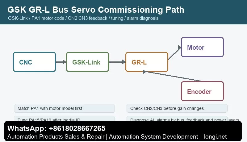
GSK GR-L bus servo GSK-Link commissioning and CN2 CN3 feedback path

GSK GR-L Bus-Type AC Servo Drive Manual Guide: GSK-Link Setup, CN2/CN3 Feedback, PA Parameters, Electronic Gear Ratio, Servo Tuning and AL Alarm Diagnosis

GR-L Is a CNC Bus Servo Axis System

GSK GR-L bus servo GSK-Link commissioning and CN2 CN3 feedback path

GSK GR-L is not just a pulse servo drive with fewer wires. It is a bus-type AC servo drive unit for CNC machine tools. The important manual topics are GSK-Link, real-time CNC communication, CN2/CN3 feedback, PA parameters, inertia identification, resonance suppression, position control, speed control and torque control.

During commissioning, do not only check whether the drive powers on or whether the motor jogs. A stable axis depends on the CNC, GSK-Link network, drive unit, motor, encoder, mechanical load and PLC diagnosis working as one closed-loop system. Fewer bus wires do not mean easier commissioning; many checks move into the CNC diagnosis screen and parameter system.

Model, Capacity and Feedback Interface

Before replacing a GR-L drive, confirm voltage class, capacity, communication interface, encoder protocol and feedback interface quantity. The manual describes CN2 and CN3 feedback interfaces and support for absolute encoders, incremental encoders, Tamagawa, BISS and EnDat2.2 protocols. Some versions use only CN2 motor feedback, while others also provide CN3 second-position feedback.

A wrong feedback interface can allow the drive to power on but still cause encoder alarms, position feedback errors, orientation failure or a bus axis that cannot be enabled. For spindle or electric-spindle applications, also confirm encoder tooth count and related feedback parameters such as PA200 where applicable.

Power Circuit, Brake and Grounding

GR-L is still a servo power unit. Input power, motor output, brake resistor, PE grounding, shielding, reactors and filters must be checked before tuning. Bus communication does not remove electrical noise. In fact, bus communication, encoder feedback and PWM motor output exist together, so wiring quality is critical.

Keep motor power cable, encoder cable and GSK-Link communication cable separated. Check brake resistor value and power rating, especially on heavy axes and spindles with frequent deceleration. Do not try to solve a wiring, grounding or braking problem by reducing servo gains.

GSK-Link Online Check

Commission the bus in three steps: confirm physical bus wiring, confirm that CNC recognizes the axis, and confirm that drive status matches CNC diagnosis. If the CNC cannot identify the servo axis, electronic gear ratio and gain tuning are meaningless.

Check station number, axis number, cable direction, termination, CNC parameters and drive state. On multi-axis machines, bring axes online one by one. This avoids mixing duplicated station numbers, cable breaks, wrong axis parameters and mechanical problems.

Panel Operation and PA Parameters

The GR-L panel is used for status display, parameter viewing, parameter editing, alarm reset and commissioning. The first key parameter is PA1, the motor model code. The manual requires selecting the motor model code and loading default motor parameters. If PA1 is wrong, current loop, speed loop, encoder setup, rated current and protection thresholds can all be wrong.

After changing important parameters, execute the required save/write operation and verify after power cycling. Record at least PA1, feedback type, second feedback configuration, electronic gear ratio, speed loop, position loop, braking, limit, alarm output and bus-axis parameters.

CN2 and CN3 Feedback

CN2 is normally motor feedback. CN3 can be used for second-position feedback such as linear scale, second spindle encoder or mechanical-end feedback. Feedback faults should be diagnosed in three layers: electrical layer, protocol layer and mechanical layer.

The electrical layer includes connector, shield, supply, cable and pin definition. The protocol layer includes encoder type, communication protocol, resolution and PA parameter match. The mechanical layer includes encoder mounting, coupling slip, scale contamination and backlash. If feedback is unreliable, gain tuning only hides the real problem.

Electronic Gear Ratio

Electronic gear ratio maps CNC command units to motor rotation, screw pitch, reduction ratio or table movement. It is not merely a speed amplifier. It directly affects command resolution, positioning accuracy, following error and machining size.

Before setting the ratio, list CNC command unit, encoder resolution, screw pitch or rotary-axis angle, gear ratio and whether second feedback is used. Start with very small low-speed motion, confirm direction, then test 1 mm, 10 mm and reverse repeatability. Proportional size error usually points to electronic gear or mechanical ratio; large bidirectional error points to backlash or feedback problems.

Inertia Identification and Servo Gain Tuning

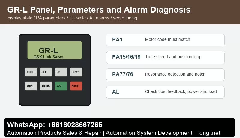
GSK GR-L servo panel PA parameters and AL alarm diagnosis

The manual separates basic performance tuning, inertia identification, speed loop, position loop and resonance suppression. The practical sequence is: confirm motor and feedback, perform inertia identification, tune speed loop, then tune position loop.

Parameters such as PA15, PA16, PA18, PA19 and PA23 relate to speed-loop and position-loop behavior. Speed gain too low causes slow response and large contour error; too high causes noise, vibration or overshoot. Position gain too low causes following error; too high causes oscillation if the machine lacks stiffness.

For multi-axis interpolation, keep dynamic response consistent between axes. The manual notes that PA19 should be handled consistently or conservatively after tuning multiple axes. Before inertia identification, ensure there is no active alarm or warning such as AL-603 and that travel is safe.

Resonance Suppression

Machine-axis screaming, vibration or surface marks at certain speed ranges can be mechanical resonance. The manual mentions real-time resonance detection and parameters such as PA77 and PA76. The idea is to detect the resonance frequency, write it into notch parameters, and adjust notch width and depth carefully.

Do not treat every vibration as resonance. Loose encoder coupling, poor bearings, dry guideways, wrong feedback direction or excessive gain can also cause vibration. Real-time detection is a commissioning tool; after identifying the frequency, save the correct notch setting and return the drive to a stable run configuration.

AL Alarm Diagnosis

Communication alarms: check GSK-Link cable, station number, axis number, termination, CNC parameters, power-on sequence and emergency stop state.

Feedback alarms: check CN2/CN3 connectors, encoder supply, shielding, protocol type, PA parameters and mechanical mounting.

Overcurrent, overload or overvoltage: check motor cable, brake resistor, mechanical jam, acceleration/deceleration time, load inertia and motor capacity.

Following error or position abnormality: check electronic gear ratio, position gain, limit signals, backlash, second-feedback direction and CNC axis parameters. Do not simply enlarge the following-error window.

Tuning warnings: clear alarms and interlocks first, confirm safe travel, then run inertia identification or resonance detection.

Commissioning Records

Before delivery, keep records of drive model, motor model, encoder type, CN2/CN3 usage, PA1, electronic gear ratio, loop gains, resonance parameters, brake settings, GSK-Link station/axis number, CNC axis parameters, PLC interlocks and alarm history.

Final testing should include jog, rapid move, homing, reverse repeatability, emergency stop, limit, servo alarm, power-cycle retention, continuous temperature rise and trial cutting. A stable GR-L servo system is not just a motor that rotates; it is an axis that the CNC can identify, the bus can maintain, feedback can prove, parameters can be traced and alarms can be diagnosed.

Posted on

GSK DAP03 Spindle Servo Manual Guide: Panel Operation, CN1 CN2 CN3 Wiring, Speed and Position Control, Electronic Gear Ratio, Parameter Write and Alarm Handling

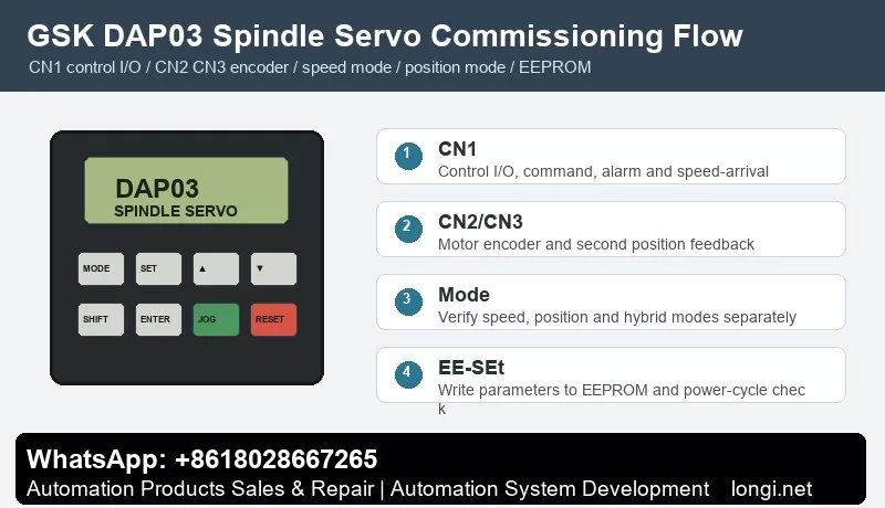
GSK DAP03 spindle servo panel operation and EEPROM parameter write

GSK DAP03 Spindle Servo Manual Guide: Panel Operation, CN1 CN2 CN3 Wiring, Speed and Position Control, Electronic Gear Ratio, Parameter Write and Alarm Handling

DAP03 Must Be Commissioned as a Closed-Loop Spindle Servo

GSK DAP03 spindle servo panel operation and EEPROM parameter write

GSK DAP03, DAY3025 and DAY3100 are spindle servo drive units. Their manual is not only about start and stop. It focuses on spindle motor control, encoder feedback, speed/position mode, CNC interface, parameter management, orientation and alarm handling.

Compared with a normal inverter, a spindle servo must care about encoder feedback, position arrival, speed arrival, electronic gear ratio, spindle orientation, braking stop and CNC machining sequence. If CNC command, CN1 control I/O, DAP03 drive, spindle motor or CN2/CN3 feedback is wrong, the drive may power on but will not run reliably.

This guide follows a field-service route: panel operation, power wiring, CN1 control signals, CN2/CN3 feedback, speed mode, position mode, electronic gear ratio, EEPROM parameter write and alarm diagnosis.

Panel Operation and Parameter Management

The DAP03 panel is used for status display, parameter selection, value editing, manual run, jog run, alarm reset and parameter management. Always read status before changing parameters. The manual separates status monitor, parameter setting and parameter management because temporary changes and permanent storage are different operations.

The manual describes EE-SEt as the operation that writes parameters from memory into the EEPROM parameter area. If a user changes a parameter but does not execute parameter write, the value may be lost at the next power-on. In the field, many “it was adjusted yesterday but failed today” cases are caused by missing EEPROM write or missing power-cycle verification.

After initialization, Err-24 may appear if CN3 is not connected to a second position encoder, and Err-5 may appear if the temperature sensor signal on CN2 is not connected. Do not replace the control board first. Check the actual hardware configuration and set the related parameters, such as PA66 and PA73, according to the application, then execute parameter write.

Power Circuit, Brake Resistor and Grounding

Before wiring, verify voltage class, drive capacity, spindle motor model, brake resistor, breaker, contactor and AC reactor. The manual includes peripheral equipment selection for protective devices and reactors, which shows that power-circuit protection is part of the drive system.

Check three points in the main circuit: input and motor output must not be reversed, the brake resistor must match the drive capacity, and PE/shield grounding must be reliable. Spindle acceleration and deceleration can regenerate significant energy. A wrong or undersized brake resistor can cause overvoltage, unstable stop or long stopping distance.

Encoder cable, CN1 control cable and motor power cable should be routed separately. Poor shielding can cause speed fluctuation, orientation failure, position deviation or feedback alarms. On retrofit machines, encoder cables should be separated from contactor coils and motor cables whenever possible.

CN1 Control Signals

The manual lists CN1 pin definition, input signals and output signals. CN1 is the key interface between CNC and spindle drive. Common signals include servo enable, forward/reverse, command input, alarm output, speed arrival, zero speed, position complete, reset and common terminal.

Do not wire every signal at once during commissioning. First connect enable and alarm output, then confirm CNC receives the drive-ready state. Next test forward/reverse or run command. Then connect speed or position command. Finally connect speed arrival, zero speed and orientation-complete feedback. A spindle running on the drive panel does not mean the CNC has received speed-arrival or position-complete feedback.

When used with GSK 218M, GSK 980TDa, GSK 980TD1 or GSK 983M, the appendix wiring examples are useful references. Still, the final wiring should follow the actual machine schematic. Pay attention to common terminals, signal polarity, alarm contact type, command type and reset pulse duration.

CN2 and CN3 Feedback Signals

The manual treats feedback wiring as a separate topic. CN2 and CN3 are related to motor encoder and second position feedback. A spindle servo is a closed-loop system; feedback disconnection, wrong signal type, poor shielding or loose connector can cause unstable speed, failed orientation, position error or alarms.

If the machine has no second position encoder but the function is enabled, Err-24 can occur after initialization. Confirm whether CN3 feedback really exists before changing hardware. If CN2 temperature or encoder-related signals are missing, the drive can also alarm. A good check sequence is: connector, shield, encoder supply, signal waveform and parameter configuration.

Feedback problems often appear only at high speed, during orientation or during rapid acceleration. Do not reduce speed-loop or position-loop gains blindly. Check encoder installation, coupling, cable shielding, grounding and CN2/CN3 connector first.

Speed Mode Commissioning

DAP03 supports speed operation mode. The manual lists analog voltage command and internal digital command. Speed mode is usually used when CNC sends spindle speed. For analog reference, confirm voltage range, direction logic, zero drift, shield and speed scaling. For internal digital command, confirm command value, run source and ramp time.

A practical test sequence is: reduce maximum speed or disconnect risky mechanical load, observe whether the speed command changes on the drive, test low-speed forward and reverse, and then increase speed while observing current, vibration, noise and temperature. If command is zero but the spindle creeps, check analog zero drift, common terminal and zero-speed clamp.

Speed-arrival feedback is important for machining sequence. If CNC sends M03 and the PLC waits for speed arrival, the program may stop if this feedback is missing. If speed-arrival is shorted falsely, feed may begin before the spindle reaches real speed.

Position Mode and Electronic Gear Ratio

The manual includes position mode, speed/position mixed mode and electronic gear ratio for position command. Position mode is used for spindle orientation, rigid tapping, tool-change positioning and angular control.

Before setting electronic gear ratio, confirm four values: CNC command pulses per revolution, encoder feedback pulses per revolution, motor-to-spindle mechanical ratio and whether belt or gear transmission is used. A wrong gear ratio causes orientation offset, inaccurate tapping pitch, repeated position drift or cumulative error.

For the first position-mode test, command only a small pulse distance and observe direction and angle. After direction is correct, verify one revolution, half revolution, orientation position and repeatability. If position arrival is unstable, check electronic gear ratio, position-arrival window, encoder feedback and mechanical backlash before tuning gains.

Brake Stop, Orientation and Interlocks

A spindle servo must not only rotate; it must stop and orient according to process requirements. The function section of the manual covers brake stop, motor direction switching, position arrival, speed arrival, zero speed and orientation. On machining centers and CNC lathes, spindle orientation is often tied to tool change, chuck, tailstock and hydraulic clamping logic.

For brake-stop faults, distinguish electrical braking, resistor braking and mechanical braking. Too short deceleration time, undersized brake resistor or high spindle inertia can cause overvoltage or unstable stop. For orientation failure, check orientation command, position feedback, electronic gear ratio, arrival window and mechanical backlash.

Do not bypass clamping and zero-speed interlocks. The PLC should link speed arrival, zero speed, orientation complete, alarm, clamp confirmation and tool-change conditions into a safe sequence.

Alarm Handling

Err-5 temperature or sensor-related alarm: after initialization or motor replacement, check CN2 temperature signal and related parameters such as PA73 before replacing hardware.

Err-24 second position feedback alarm: if CN3 is not connected but the function is enabled, check configuration such as PA66. If second feedback exists, inspect encoder supply, shield, signal and mechanical mounting.

No rotation in speed mode: check enable, run command, direction, speed command, analog common, E-stop and alarm reset.

Positioning error in position mode: verify electronic gear ratio, feedback pulses, mechanical ratio, direction, arrival window and backlash.

Alarm immediately after run command: check motor power cable, encoder cable, brake resistor, mechanical binding, ramp time and load inertia.

Parameters lost after power cycle: confirm EE-SEt parameter write and verify again after power-off and restart.

Delivery Checklist

  • Backup: speed mode, position mode, electronic gear, encoder, brake and alarm parameters.
  • Wiring record: CN1, CN2, CN3, power circuit, brake resistor and shield grounding.
  • Function test: low-speed forward/reverse, speed arrival, zero speed, orientation, position complete, alarm output and reset.
  • Safety interlock: no feed before speed arrival, no unclamp before zero speed, no start before alarm reset.
  • Final check: execute parameter write, power cycle and verify critical actions again.

The core of DAP03 commissioning is simple: make feedback reliable first, stabilize speed mode second, make position mode accurate third, then connect speed arrival, zero speed, orientation and PLC interlocks into the machine sequence.

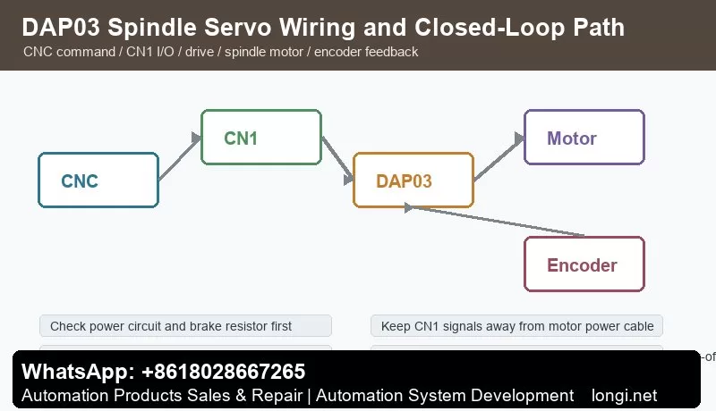
GSK DAP03 CN1 CN2 CN3 wiring and closed-loop spindle servo control
Posted on

HNC-808GCE CNC Manual Guide: Operator Panel, I/O Wiring, Servo Connection, Parameter Setup, PLC Diagnosis, G-Code Test and Fault Handling

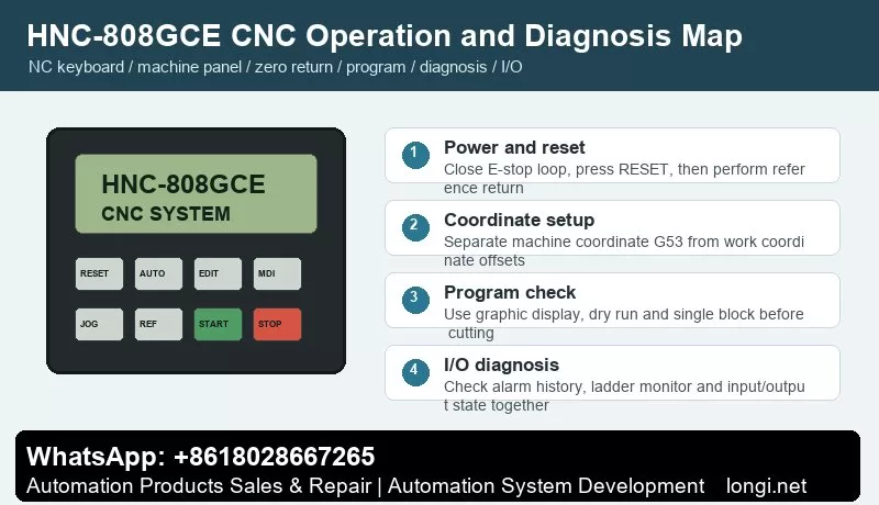
HNC-808GCE CNC operator panel and diagnosis map

HNC-808GCE CNC Manual Guide: Operator Panel, I/O Wiring, Servo Connection, Parameter Setup, PLC Diagnosis, G-Code Test and Fault Handling

Read the HNC-808GCE Manual as a Complete Machine System

HNC-808GCE CNC operator panel and diagnosis map

HNC-808GCE is not just a display unit or a simple PLC. It is a CNC system for grinding-machine applications. The manual covers NC programming, coordinate systems, G/M/S/T commands, grinding cycles, macro programs, machine operation, reference return, program editing, diagnosis, I/O, RS232, bus I/O, power supply and grounding.

The most common service mistake is to focus on one alarm and ignore the relationship among CNC, I/O, servo drives, spindle drive, operator panel and PLC ladder logic. A reliable troubleshooting order is: power and emergency stop first, CNC status second, I/O state third, servo ready and alarm chain fourth, CNC parameters and PLC program last.

This guide turns the manual into a practical field procedure: panel operation, wiring and servo connection, low-level parameter setup, simple PLC diagnosis, G-code verification and fault handling.

Operator Panel: Read Status Before Running a Program

The HNC-808GCE operating station normally includes a display, NC keyboard, machine control panel and optional handwheel unit. The display is used for coordinates, program text, graphics, alarms, ladder monitor and I/O state. The NC keyboard is used for menu navigation, editing, parameter setting and diagnosis. The machine panel handles cycle start, feed hold, emergency stop, mode selection, override, spindle and coolant functions.

After power-on, do not press cycle start immediately. Check whether the system has booted normally, the emergency stop circuit is released, servo drives are ready and each axis has completed reference return if required. Reset is not a substitute for fault removal. If an E-stop input, servo alarm or limit input is still active, repeated reset only hides useful diagnostic information.

Reference return must be separated from work offset setting. Machine coordinate is the basis for travel limits and reference position; work coordinate is used by the machining program. The manual covers G53 machine coordinate, work coordinate, programming zero, G90/G91 absolute and incremental commands and G17/G18/G19 plane selection. For service work, observe reference switch and deceleration switch states in diagnosis before moving the axis.

Before actual grinding, use three checks: graphic display to inspect path direction and travel range, dry run with low override, and single-block execution to verify M-code actions such as spindle, coolant, wheel dressing, clamping and interlocks.

I/O Wiring and Servo Connection

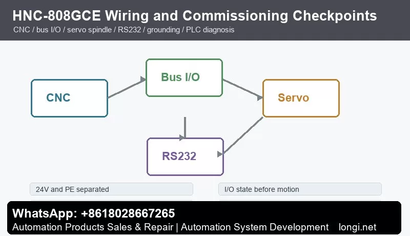
HNC-808GCE CNC wiring servo I/O and commissioning checkpoints

The connection section of the manual covers integrated wiring, bus I/O, power supply, grounding, RS232 and links between CNC and bus I/O units. In the cabinet, wiring can be divided into four groups: system power and grounding, operator-panel I/O, servo and spindle interfaces, and communication/remote I/O.

Power wiring must separate 24 V, 0 V, PE and shield grounding. If sensors, relays, servo enable circuits and I/O modules share one supply, verify current capacity and common return paths. Encoder cables, analog signals and motor power cables should not be bundled together. Intermittent alarms, position jumps and communication errors often come from grounding or shielding rather than from CNC parameters.

I/O diagnosis should be based on the CNC diagnosis screen. Emergency stop, cycle start, feed hold, door switch, lubrication pressure, hydraulic pressure, limit switch, reference switch, servo ready and spindle ready should all change state on the CNC display. Measuring 24 V with a meter is not enough; the CNC internal state must change as well.

Servo connection normally includes command or bus communication, enable, alarm, ready signal, encoder feedback and motor power. For bus servo systems, station number, axis number and servo parameters must match the CNC configuration. For pulse or analog interfaces, confirm direction polarity, pulse type, enable logic, alarm contact type and shield grounding. For spindle drives, also check spindle enable, forward/reverse, speed reference, speed-arrival signal, alarm and brake logic.

Low-Level Parameter Setup

Before any repair, retrofit or board replacement, back up CNC parameters and PLC data. At minimum, record system model, software version, number of axes, pulse equivalent or bus configuration, servo model, spindle configuration, I/O assignment, soft limits, reference direction, reference speed, backlash compensation, pitch compensation, work offsets and macro variables.

Treat parameters in layers. The first layer is safety: emergency stop, limits, soft limits, reference direction, travel range and servo-alarm handling. The second layer is motion: axis direction, speed, acceleration/deceleration, interpolation and following-error limits. The third layer is process: spindle, wheel dressing, coolant, clamping and lubrication. The fourth layer is communication and expansion: RS232, DNC, USB, bus I/O and remote I/O.

After restoring parameters, do not run a production program immediately. Boot the CNC, confirm keyboard and display, check emergency stop and reset, observe I/O state, return each axis to reference, jog at low speed, test spindle and M-code actions, and then dry-run a simple program.

Simple PLC Diagnosis and Editing Logic

The manual highlights alarm display, alarm history, ladder monitor, input/output and status display. A service engineer does not need to rewrite the whole PLC, but must understand input contacts, output coils, internal relays, timers, interlocks and alarm conditions.

A practical PLC logic chain is: input condition, internal permission, output action, feedback confirmation and alarm handling. For coolant, an M08 command should check E-stop, door, level and other permissions before enabling the coolant output; if pressure feedback is missing within the allowed time, the PLC should generate an alarm. For hydraulic clamping, the clamp output should wait for clamp-confirm feedback before allowing spindle and feed motion.

Never bypass emergency stop, limit or servo-alarm signals as a permanent solution. Temporary jumper tests may be used only for diagnosis in a safe stopped condition, and the real safety chain must be restored before trial running.

G-Code Test Programs for Commissioning

The programming part of the manual covers G00, G01, G02/G03, G04, G17/G18/G19, G90/G91, G20/G21, G53, M98, G65, M commands, S/T commands and grinding-related cycles. In service work, short test programs are more valuable than complex production programs.

Use a simple linear-axis program to verify coordinate direction and feed. Use a low feed rate, G90 absolute mode and a small travel range. For arc interpolation, confirm the correct plane with G17, G18 or G19 before running. For M-code tests, run spindle forward, reverse, stop, coolant on/off, clamp and unclamp separately while watching PLC outputs and feedback inputs.

Grinding machines require special attention to wheel dressing, feed hold, optional stop, single block and restart after interruption. After wheel dressing, verify compensation, coordinate update and dresser limit signals. First dry-run the path, then run low-speed motion without workpiece, and only then start actual grinding.

Common Faults and Diagnostic Handling

No display or no boot: check incoming power, UPS or switching power supply, 24 V supply, fuses, grounding and display cable. If the fan runs but the screen is dark, check the display link and IPC unit.

E-stop or external alarm remains after reset: inspect diagnosis I/O for E-stop, door, hydraulic pressure, lubrication, servo alarm and spindle alarm. Do not rely only on the physical button position.

Reference return fails: check reference mode, direction, deceleration switch, reference switch, servo enable, axis limit and reference speed. If motion direction is wrong, verify by low-speed jog before changing direction parameters.

Program cannot start: check auto mode, selected program, reference return completion, feed override, cycle-start input, PLC permission and unreset alarms.

Axis motion alarm or following error: check the servo drive alarm first, then motor power cable, encoder cable, brake, mechanical binding, lubrication, ball screw and load. If no-load motion is normal but loaded motion trips, focus on mechanical load, servo gain and acceleration settings.

I/O does not operate: decide whether the input is missing, PLC condition is false, or the output relay/final device is faulty. Use the diagnosis screen, ladder monitor and meter together.

RS232 or DNC communication fails: check cable type, baud rate, data bits, stop bits, parity, file name and transfer direction. USB-to-serial adapters can also cause compatibility problems on older machines.

Delivery Checklist

  • Backup: CNC parameters, PLC, I/O table, compensation data and macro variables.
  • Safety chain: emergency stop, door, limits, servo alarm, spindle alarm, hydraulic and lubrication signals.
  • Motion chain: jog, reference return, soft limit, override, single block, dry run, pause and restart.
  • Process chain: spindle, wheel dressing, coolant, clamp, unclamp, lubrication and chip removal actions.
  • Records: software version, parameter version, PLC version, changes made and remaining risks.

The value of the HNC-808GCE manual is not only in listing keys and commands. It gives a complete closed loop from programming and operation to wiring and diagnosis. Follow the order of status confirmation, I/O diagnosis, servo check, parameter verification, PLC logic and program test, and most start failures, reference-return problems, I/O faults and servo alarms can be located methodically.

Posted on

AnyHz FST-650 Inverter Err20 Encoder Fault Analysis and Complete Troubleshooting Guide

Introduction

With the rapid development of industrial automation, variable frequency drives (VFDs) have evolved from simple motor speed regulators into intelligent drive systems integrating motor control, speed feedback, torque management, communication functions, and advanced fault diagnosis.

In applications requiring high speed accuracy and dynamic response, such as machine tools, cranes, textile equipment, printing machinery, packaging lines, and automated production systems, closed-loop vector control with encoder feedback has become increasingly common.

The AnyHz (Foster Technology) FST-650 series is a high-performance vector control inverter that supports multiple control modes, including:

  • V/F control;
  • Sensorless vector control;
  • Closed-loop vector control with encoder feedback.

When the FST-650 displays the fault code Err20, the inverter has detected an abnormality in the encoder feedback system.

The meaning of Err20 is:

Err20 = Encoder Fault / PG Card Fault

However, in practical maintenance work, Err20 does not always mean that the encoder itself is damaged. Many real-world cases are caused by:

  • Incorrect control mode selection;
  • Wrong encoder parameter settings;
  • Encoder wiring problems;
  • Missing encoder power supply;
  • PG card failure;
  • Incorrect replacement configuration.

This article provides a detailed analysis of the working principle behind Err20, common causes, diagnostic procedures, and repair methods to help engineers quickly troubleshoot AnyHz FST-650 encoder-related faults.


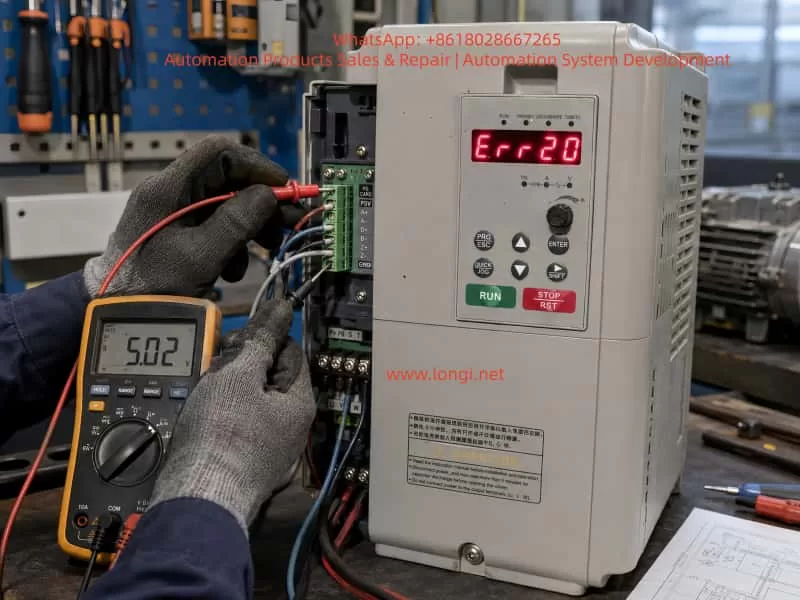
Technician troubleshooting AnyHz FST-650 inverter Err20 encoder fault using a multimeter to check PG card and encoder feedback wiring in an industrial maintenance workshop

1. Working Principle of Err20 Fault in FST-650 Inverter

1.1 The Role of Encoder Feedback in Closed-Loop Vector Control

A conventional inverter operating in open-loop mode controls the motor based on the output frequency and voltage.

For example:

  • Frequency command: 50Hz;
  • Output voltage calculated according to motor model;
  • Motor speed estimated by inverter algorithm.

This type of control does not require an encoder.

However, in closed-loop vector control, the inverter must continuously know:

  • Actual motor speed;
  • Rotor position;
  • Rotation direction;
  • Speed deviation.

Therefore, an encoder is installed on the motor shaft.

The control process is:

Speed Command
      ↓
Vector Control Algorithm
      ↓
IGBT Output Three-Phase Power
      ↓
Motor Rotation
      ↓
Encoder Detects Actual Speed
      ↓
PG Card Processes Feedback Signal
      ↓
CPU Receives Feedback Data
      ↓
Adjusts Output Frequency and Torque

The encoder acts like the “eyes” of the inverter.

If the encoder signal disappears, the inverter cannot accurately determine the motor operating condition, so it triggers Err20 protection.


2. Main Causes of AnyHz FST-650 Err20 Fault

According to the FST-650 technical documentation, Err20 is mainly related to encoder feedback abnormalities. The possible causes include:

  1. Incorrect encoder type setting;
  2. Incorrect encoder wiring;
  3. Damaged encoder;
  4. Faulty PG feedback card.

In practical applications, these causes can be divided into several categories.


2.1 Incorrect Encoder Type Setting

This is one of the most common reasons for Err20.

The FST-650 supports different feedback devices, such as:

  • Incremental AB encoder;
  • ABZ encoder;
  • UVW encoder;
  • Resolver.

Different encoder types output completely different signals.

For example:

Actual hardware:

Incremental encoder
A+
A-
B+
B-

But inverter parameter setting:

UVW encoder

The encoder itself may be working normally, but the inverter receives an incompatible signal format.

The result:

Encoder signal abnormal
        ↓
No valid speed feedback
        ↓
Err20 alarm

2.2 Encoder Wiring Failure

Encoder systems usually contain several signal lines:

SignalFunction
+5VEncoder power supply
GNDPower ground
A+Channel A positive signal
A-Channel A negative signal
B+Channel B positive signal
B-Channel B negative signal
Z+Zero pulse signal
Z-Zero pulse return signal

Any problem in these connections may cause Err20.

Common wiring problems include:

  • Broken encoder cable;
  • Loose connector;
  • Poor grounding;
  • Incorrect phase connection;
  • Damaged shielding layer.

For example:

If the encoder power supply line is disconnected:

Encoder has no power
        ↓
No pulse output
        ↓
PG card receives no signal
        ↓
Err20

2.3 Encoder Damage

Encoders are precision electronic components. Long-term operation may cause:

  • Optical sensor aging;
  • Internal IC failure;
  • Mechanical shaft damage;
  • Dust or moisture contamination;
  • Vibration damage.

Typical symptom:

The inverter powers on normally.

However:

When the motor starts running:

Motor rotates
       ↓
Encoder should output pulses
       ↓
No feedback detected
       ↓
Err20 appears

At standstill, the problem may not be obvious because the encoder is not generating speed pulses.


2.4 PG Card Failure

The PG card is the interface between the encoder and inverter CPU.

Its function:

Encoder signal
       ↓
Signal conditioning
       ↓
Voltage conversion
       ↓
Filtering
       ↓
CPU feedback input

If the PG card fails, even a good encoder cannot provide feedback to the inverter.

Typical PG card failures:

  • Input circuit damage;
  • RS422 receiver failure;
  • Optical isolation failure;
  • Power supply abnormality;
  • Poor connector contact.

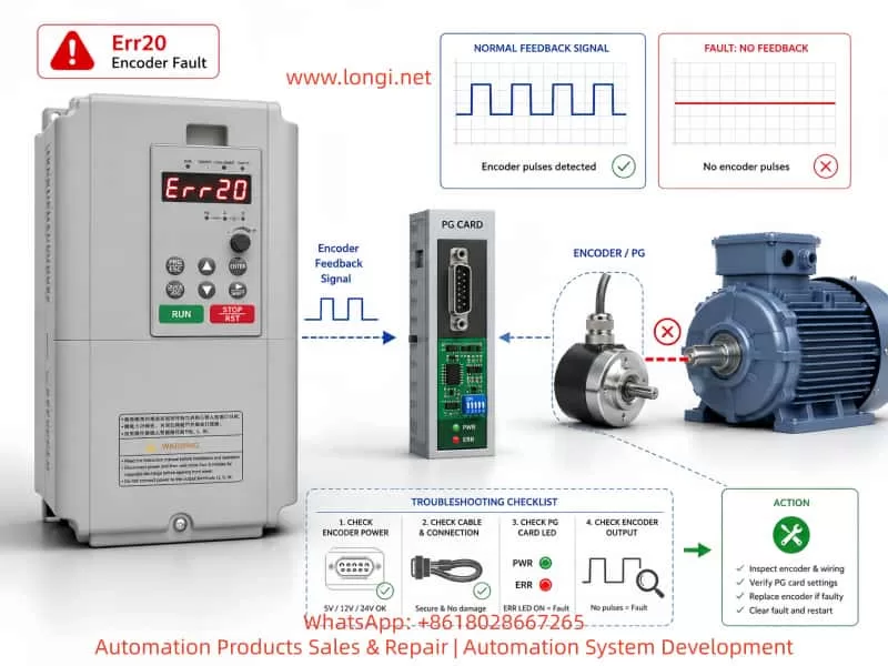
Technical diagnostic illustration showing AnyHz FST-650 inverter Err20 encoder fault troubleshooting process with encoder, PG card, motor feedback signal flow, pulse waveform analysis, and fault inspection steps

3. First Maintenance Step: Confirm Whether an Encoder Is Actually Required

A very common situation in the field is:

The inverter reports Err20, but the motor does not have an encoder.

This usually happens after:

  • Parameter reset;
  • Replacement of inverter;
  • Second-hand equipment installation;
  • Incorrect commissioning.

Example:

Original system:

Standard motor
+
V/F control

After parameter modification:

Closed-loop vector control enabled

The inverter starts searching for encoder feedback:

No encoder signal
        ↓
Err20

Check Control Mode Parameter

Enter the inverter parameter menu and check the control mode.

If the inverter is set to:

Closed-loop vector control

then the system must have:

  • Encoder;
  • PG card;
  • Correct encoder parameters.

If the machine does not use an encoder, change the control mode to:

V/F Control

or:

Sensorless Vector Control

Then save the parameters and restart the inverter.


4. Complete Err20 Troubleshooting Procedure

The following procedure is suitable for field maintenance.


Step 1: Determine When Err20 Appears

Situation A: Err20 appears immediately after power-on

Possible causes:

  • Wrong parameters;
  • PG card failure;
  • Encoder configuration mismatch.

Focus on:

  • Control mode;
  • Encoder type;
  • PG card installation.

Situation B: Err20 appears only after motor starts

Possible causes:

  • Encoder signal loss;
  • Encoder cable problem;
  • Encoder damage.

Focus on:

  • Encoder output waveform;
  • Cable continuity;
  • Mechanical installation.

Step 2: Check Whether a PG Card Exists

Open the inverter control section.

Confirm whether a PG expansion card is installed.

If:

  • Control mode = closed-loop vector;
  • No PG card installed;

then Err20 is expected.

The solution is:

Change the control mode.


Step 3: Check Encoder Power Supply

Use a multimeter.

Measure:

Encoder +5V – GND

Normal value:

Approximately:

5V DC

If voltage is:

  • 0V;
  • unstable;
  • significantly lower;

check:

  • PG card power supply;
  • Cable short circuit;
  • Encoder internal failure.

Step 4: Check Encoder Output Signal

For incremental encoders:

Rotate the motor shaft manually.

The A and B channels should generate pulse changes.

Normal signal:

A channel:

0V → 5V → 0V → 5V

B channel:

Phase shifted 90° from A channel

If there is no signal:

Possible causes:

  • Encoder failure;
  • Missing power supply;
  • Broken cable.

Step 5: Verify Encoder Parameters

Important parameters include:

Encoder Type

The inverter setting must match the actual encoder.

Example:

Actual:

AB incremental encoder

Parameter:

AB encoder

Incorrect:

Resolver

or:

UVW encoder

Encoder Resolution

Example:

Encoder nameplate:

1024 P/R

Parameter must be:

1024

Incorrect pulse number settings may cause:

  • Incorrect speed feedback;
  • Speed deviation;
  • Err20 alarm.

5. Typical Field Repair Case

Fault Description

A machine equipped with AnyHz FST-650 inverter shows:

Err20

The motor cannot start.


Inspection Results

  1. Motor has no encoder;
  2. No PG card installed;
  3. Inverter configured for closed-loop vector control.

Fault Analysis

The inverter entered closed-loop vector mode.

The CPU expected encoder feedback.

However:

No encoder signal existed.

Therefore:

Missing feedback
        ↓
Encoder fault detection
        ↓
Err20

Solution

Change control mode:

Closed-loop vector control
              ↓
Sensorless vector control

Save parameters.

Power cycle inverter.

Result:

Machine returns to normal operation.


6. Precautions When Replacing an Encoder

Replacing an encoder is not simply a matter of installing a new component.

Several factors must be considered.


6.1 Mechanical Installation

The encoder shaft must be:

  • Properly aligned;
  • Concentric with the motor shaft;
  • Mechanically fixed.

Poor installation may cause:

  • Vibration;
  • Pulse loss;
  • Feedback instability.

6.2 Rotation Direction Verification

If A/B phase sequence is reversed:

Symptoms:

  • Motor rotates opposite direction;
  • Speed feedback abnormal.

Solutions:

  • Exchange A and B signals;
  • Modify encoder direction parameter.

6.3 Encoder Resolution Matching

The replacement encoder must have the same resolution.

Example:

Original:

2048 P/R

Replacement:

1024 P/R

may cause:

  • Incorrect speed calculation;
  • Speed deviation;
  • Control instability.

7. Difference Between Err20 and Other FST-650 Faults

Correct fault identification prevents unnecessary replacement.

Err19

Motor auto-tuning fault.

Common causes:

  • Incorrect motor parameters;
  • Auto-tuning failure.

Err20

Encoder feedback fault.

Focus on:

  • Encoder;
  • PG card;
  • Feedback wiring;
  • Encoder parameters.

Err21

EEPROM read/write fault.

Usually related to:

  • Control board memory;
  • Parameter storage failure.

8. Recommended Repair Strategy

For AnyHz FST-650 Err20 faults, follow this sequence:

1. Confirm control mode

Does the application actually require an encoder?


2. Check PG card

Verify:

  • Installed or not;
  • Connector condition;
  • Power supply.

3. Check encoder power

Confirm:

+5V supply is stable

4. Check encoder output

Verify:

  • A/B pulse signals;
  • Signal quality;
  • Cable condition.

5. Verify parameters

Confirm:

  • Encoder type;
  • Pulse number;
  • Motor parameters.

Conclusion

The AnyHz FST-650 Err20 fault is essentially a protection response caused by abnormal speed feedback in the closed-loop vector control system.

Although the display message indicates an “encoder fault”, the actual cause may exist in multiple areas:

  • Incorrect control mode;
  • Wrong encoder configuration;
  • Wiring problems;
  • Encoder power failure;
  • PG card damage;
  • Encoder hardware failure.

In practical maintenance work, engineers should avoid immediately replacing the encoder. A systematic troubleshooting approach is more effective:

Control Mode Verification → PG Card Inspection → Encoder Power Check → Signal Measurement → Parameter Verification → Hardware Replacement

Understanding the operating principle of closed-loop vector control allows technicians to diagnose FST-650 Err20 faults faster, reduce unnecessary component replacement, and improve industrial equipment maintenance efficiency.

Posted on

From F2044 to F2042: Offline Diagnosis, Communication Identification, and Safe Bench Testing of a Bosch Rexroth IndraDrive C Dual-Encoder Servo System

In paper machinery, winding equipment, printing lines, coating machines, textile machinery, metal processing lines, and continuous feeding systems, a high-power servo drive often does much more than simply rotate a motor. It may also participate in speed synchronization, tension control, line-speed measurement, measuring-roll feedback, position compensation, and machine interlocking.

Therefore, when a Bosch Rexroth IndraDrive C system is removed from a customer’s machine and brought to a repair workshop, it usually cannot be tested like an ordinary inverter. Supplying three-phase power, 24 V control power, and connecting the motor is often not enough to make the drive run. The real difficulty is not only determining whether the power module is damaged, but also understanding the original control architecture, encoder topology, external I/O supply, serial communication control, and parameter logic.

This is especially true for an IndraDrive C system equipped with a configurable control section, X15 parallel I/O interface, X2 serial communication, and an external measuring-roll encoder. During startup, the drive checks several conditions in sequence. After one fault is removed, the next deeper-level fault may appear. For example, when F2044 is cleared and F2042 appears afterward, this does not necessarily mean a new fault has been created. It often means the drive has passed the previous external I/O power check and has now started checking the encoder feedback chain.

This article uses a typical HCS03.1 high-power IndraDrive C system with a CSB01.1C control section, external measuring encoder, and PLC serial control architecture as an example. It explains how to diagnose the drive offline, identify the real function of each interface, understand F2044 and F2042, connect IndraWorks Ds through X2, avoid unsafe parameter changes, and establish a safe temporary bench-test method.


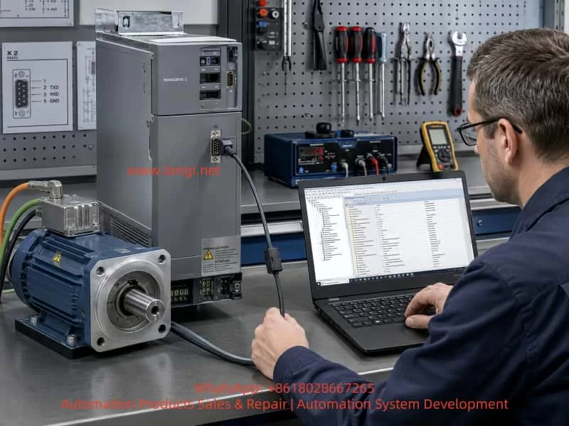
Bosch Rexroth IndraDrive C servo drive and industrial motor connected on a repair bench, with a technician using a laptop for parameter diagnostics through the X2 serial interface.

1. IndraDrive C Is Not an Ordinary VFD

A Bosch Rexroth IndraDrive C drive consists of a power section and a control section. The power section handles three-phase rectification, DC bus energy, inverter output, braking chopper operation, thermal management, and motor power output. The control section handles motion control, encoder evaluation, digital I/O, communication, diagnostics, parameter management, and interaction with PLC or CNC systems.

For example, the drive model:

HCS03.1E-W0150-A-05-NNBV

belongs to the high-power compact IndraDrive C series. It is typically used for large main drives, winding rollers, drawing rollers, tension-control systems, and other high-torque servo applications. This type of drive must not be treated like a small servo amplifier or a basic frequency inverter during bench testing.

A key point is that the same HCS03 power section can be fitted with different control sections. The control section determines which interfaces and functions are available: serial communication, Profibus, SERCOS, analog input, parallel I/O, encoder options, positioning mode, spindle mode, or speed synchronization.

Therefore, before testing the drive, the technician must identify three things:

Power section model
Control section model
Firmware and parameter set

Looking only at the power section model is not enough. The real control logic is determined by the control section, firmware, and application parameters.


2. Correctly Identifying X2, X4, X8, and X15

In this case, the control section model is:

CSB01.1C-PL-ENS-EN2-...

The important parts are:

CSB01.1C = configurable single-axis control section
PL       = parallel interface option
ENS      = standard encoder interface
EN2      = second encoder / optional encoder interface

This means the drive is not a simple fixed-I/O unit. It is a configurable drive that can be controlled through communication, mapped I/O, and encoder functions.

The important connectors are:

X2   = RS232 serial interface
X15  = parallel I/O interface
X4   = optional encoder / measuring encoder interface
X8   = motor encoder or standard feedback interface

In the customer’s electrical drawing, the system uses two encoders:

X8 → motor encoder
X4 → measuring-roll encoder

This means the motor encoder and measuring encoder are both part of the original system. The motor encoder is used for motor feedback, speed control, and commutation. The measuring-roll encoder is likely used for actual material speed, length measurement, synchronization, or tension-related control.

If only the motor and drive are brought to the workshop while the measuring-roll encoder remains on the machine, the drive may report an encoder-related fault because the original parameter set still expects Encoder 2 to exist.


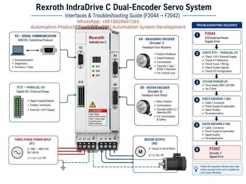
Technical diagram of a Rexroth IndraDrive C dual-encoder servo system showing X2 serial communication, X15 parallel I/O power supply, X4 measuring encoder, X8 motor encoder, three-phase input, motor output, and F2044 to F2042 troubleshooting sequence.

3. F2044 and F2042 Must Be Understood as Sequential Diagnostics

When the drive is powered on without the required X15 external I/O supply, it may display:

F2044
External power supply X15 error

This means the X15 external I/O power supply is missing, incorrect, or not detected. For a control section with a parallel interface, X15 is not just an optional connector. It may be used for inputs, outputs, enable chains, interlocks, status signals, and machine logic.

After the X15 external 24 V supply is connected correctly, F2044 may disappear. Then the drive continues checking the next required conditions. If the next displayed fault is:

F2042
Encoder 2: encoder signals incorrect

this usually means the drive has now detected a problem with the second encoder channel. In this case, the second encoder corresponds to the external measuring-roll encoder that is missing from the bench setup.

This sequence is normal:

X15 not powered → F2044
X15 powered correctly → F2044 cleared
Missing Encoder 2 → F2042

Therefore, F2042 after F2044 does not automatically mean the drive or motor has been damaged. It means the diagnosis has moved to the next dependency.


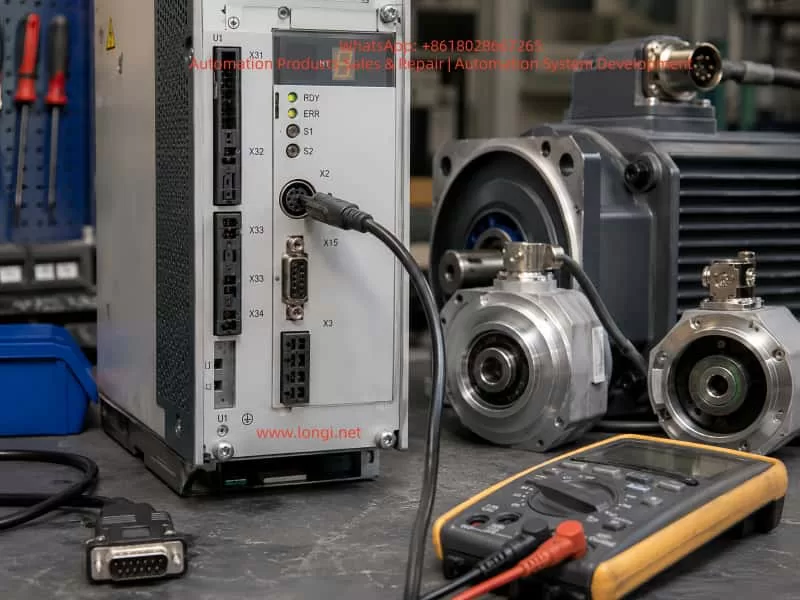
Close-up of an industrial servo drive test setup with Bosch Rexroth IndraDrive interfaces, connected encoder cables, servo motors, D-sub connector, and digital multimeter on a maintenance workbench.

4. Supplying X15 with 24 V Does Not Mean the Drive Can Run from I/O

Many technicians assume that once X15 has 24 V, the motor can be started by applying 24 V to a few digital inputs. This is not always true.

On a configurable IndraDrive control section, the physical X15 pins are only hardware inputs and outputs. Their actual function is defined by parameters. One input may be mapped as Drive ON in one project, but as a limit switch, mode selector, reset, external interlock, or PLC handshake signal in another project.

Possible functions include:

Drive ON
Drive Halt
Fault Reset
Jog +
Jog -
Forward
Reverse
External enable
Mode selection
Limit switch
PLC interlock
Status feedback

Therefore, knowing the physical pin number is not enough. The current parameter mapping must also be known.

In this case, the customer’s electrical drawing shows a PLC serial communication path:

PLC serial module
↓
RS485
↓
HAS05.1-005 RS232/RS485 converter
↓
Drive X2

This strongly suggests that the original machine does not use X15 as the main command source. Instead, the PLC probably sends the control word, speed command, enable sequence, reset, and operating mode through X2 communication.

So X15 power is required to clear F2044, but X15 may not have authority to start the motor unless the control source and I/O mapping are changed.


5. X2 Is the Key Diagnostic Interface

The X2 connector on this IndraDrive is an 8-pin Mini-DIN RS232 serial interface. It is used for:

Parameter reading
Parameter writing
Diagnostics
Fault history
DriveTop / IndraWorks communication
Serial master control
Connection to RS232/RS485 converter

The correct X2 pin assignment is:

1 = RTS
2 = CTS
3 = TxD
4 = GND
5 = RxD
6 = Vcc
7 = n.c.
8 = n.c.

For connection to a PC through RS232, the basic wiring is:

Drive X2-3 TxD → PC DB9-2 RxD
Drive X2-5 RxD → PC DB9-3 TxD
Drive X2-4 GND → PC DB9-5 GND

X2-6 is Vcc and should not be connected to the PC serial port. X2 is RS232, not TTL and not RS485. A USB-TTL adapter must not be connected directly to X2. If the computer has no real serial port, a proper USB-RS232 adapter should be used.

The original machine may use a HAS05.1-005 converter. This converter allows the PLC RS485 side to communicate with the drive’s RS232 X2 port. Therefore, the field system may look like RS485 from the PLC side, but the drive X2 itself remains RS232.


6. The Standard Four-Key Panel Cannot Replace IndraWorks Ds

The small four-key panel on the drive usually has:

Esc
Up
Down
Enter

It can be used for basic status display, fault display, simple command confirmation, and limited menu operations. However, it is not suitable for full parameter work.

It cannot reliably perform these tasks:

Export complete parameter set
View all P-0 parameters
View all S-0 parameters
Edit encoder configuration safely
Compare original and modified parameters
Change control source mapping safely
Check live X15 input status
Check serial communication status
Save and restore complete parameter files

For this case, the correct tool is:

IndraWorks Ds
or IndraWorks Engineering with drive commissioning functions

A comfort control panel may allow more parameter editing than the standard four-key panel, but for a repair workshop, software is much safer because it allows parameter backup, comparison, online diagnostics, and easier restoration.

Before changing anything, the technician should connect through X2, read the drive online, and save the original parameters.


7. Easy Startup Is a Temporary Test Method, Not a Permanent Machine Solution

IndraDrive provides an Easy Startup function for commissioning and temporary testing. When activated, it can temporarily bypass the original master communication and allow simplified local test operation.

The key point is that Easy Startup is not intended to permanently replace the original PLC or CNC logic. It is useful for bench testing because it can help verify:

Drive power section
Motor feedback
Motor rotation
Basic speed control
Low-speed operation
Fault response

However, Easy Startup cannot replace the original measuring-roll synchronization, tension control, PLC logic, line-speed control, or production process control.

For a repair bench, Easy Startup is useful only after the basic faults have been cleared:

X15 external power OK
Encoder faults resolved or temporarily configured
Motor feedback correct
Main power safe
Emergency stop available
Motor mechanically fixed

It should not be used as a permanent operating mode for the customer’s machine.


8. Encoder 2 Should Not Be Permanently Disabled Without Understanding the Machine Function

When F2042 appears, one possible temporary test method is to disable Encoder 2 in the parameter set. However, this must be treated as a temporary bench-test action only.

The external measuring encoder may be used for:

Actual material speed
Line speed measurement
Length counting
Tension control
Slip detection
Roll diameter compensation
Synchronization
Feed ratio calculation

If it is permanently disabled, the motor may run, but the machine process may become invalid or unsafe.

Possible consequences include:

Incorrect line speed
Incorrect length measurement
Unstable tension
Roll synchronization error
Material breakage
Slip not detected
Wrong feed ratio
Unexpected speed correction

A safer temporary method is to connect a compatible test encoder to X4. If the original measuring encoder used 8 wires:

+5V
0V
A / A-
B / B-
Z / Z-

then the temporary encoder must be a 5 V TTL differential or RS422 line-driver type. It must not be a 24 V encoder, NPN encoder, PNP encoder, or open-collector single-ended encoder.

Even if the electrical signals are compatible, the pulse count may be different from the original encoder. This may clear F2042 but still make the machine measurement wrong. That is acceptable only for bench testing, not for final machine operation.


9. A Correct Offline Diagnosis Sequence

For a complex IndraDrive C system, the correct sequence is more important than speed.

Step 1: Identify all hardware

Record:

Power section model
Control section model
Firmware version
Motor model
Motor encoder type
External encoder type
PLC model
Communication module
HAS05 converter model
Brake resistor
Original cable connections

Step 2: Preserve original information

Before removing or changing wires, take photos of:

X15 wiring
X2 communication cable
X4 encoder cable
X8 motor encoder cable
Motor power cable
Brake resistor cable
Main power cable
24 V wiring
Grounding
PLC terminal numbers

Step 3: Clear basic power-related faults

If F2044 is present, solve the X15 external 24 V power issue first. Do not attempt to start the drive while F2044 is active.

Step 4: Resolve encoder faults

If F2042 appears after F2044 is cleared, check whether Encoder 2 is missing, incorrectly wired, or expected by the parameter set.

Step 5: Confirm the real control source

Determine whether the drive is controlled by:

X2 serial communication
Profibus
SERCOS
Analog input
X15 parallel I/O
Easy Startup
Local software test mode

Do not assume X15 can start the drive unless the parameter mapping confirms it.

Step 6: Back up parameters before modification

Before disabling Encoder 2 or switching to local I/O control, save the full parameter set. Never perform Load Defaults or firmware updates without a backup.

Step 7: Perform only low-speed bench testing

The motor must be mechanically fixed. Use low speed, low torque, short test duration, and a real emergency stop. A high-power 30 kW motor with high torque must never be allowed to run freely on a bench.


10. Parameter Modification Principles

Any parameter change must follow four principles:

Backup first
Change as little as possible
Record original values
Restore after testing

Do not perform:

Load Defaults
Factory reset
MMC parameter loading
Firmware upgrade
Random I/O remapping
Permanent encoder disabling
Permanent control source change

Without a parameter backup, even a simple change can make the drive incompatible with the customer’s PLC program or mechanical system.

Important parameter groups include:

Encoder 1 configuration
Encoder 2 configuration
Optional encoder assignment
Control word source
Speed command source
Communication settings
I/O mapping
Operating mode selection
Drive Halt / Drive ON logic

The exact parameter names and values may vary by firmware version. Therefore, the correct procedure is to go online with IndraWorks Ds, read the current values, save the parameter file, and only then make temporary modifications.


11. “Motor Can Rotate” Does Not Mean “Machine Is Repaired”

For a high-power servo system, testing should be divided into levels.

Level 1: Drive powers up correctly

Confirm:

Display works
No fatal hardware fault
No F2044
Control section identified
Parameters readable
Software can connect

Level 2: Feedback and interlocks are valid

Confirm:

Motor encoder OK
External encoder OK or temporarily handled
Temperature feedback OK
Drive Halt status correct
Emergency stop available
Grounding correct
Main contactor logic safe

Level 3: Low-speed motor operation

Confirm:

Motor turns in the correct direction
No abnormal noise
Current is stable
Feedback is stable
No encoder jumping
No DC bus abnormality
Stop behavior normal

Level 4: Machine process operation

Confirm:

PLC communication normal
Measuring-roll feedback normal
Line-speed calculation correct
Tension stable
Synchronization correct
Original machine logic restored

Only Level 4 proves the customer’s machine is truly restored. A successful bench spin only proves that the drive and motor can run under simplified conditions.


Conclusion

The diagnosis of a Bosch Rexroth IndraDrive C high-power servo system cannot be reduced to simply applying power and forcing an enable input. A system with HCS03.1 power section, CSB01.1C control section, X15 parallel I/O, X2 serial communication, motor encoder, and external measuring encoder must be treated as a complete motion-control system.

F2044 indicates that the X15 external I/O power supply is missing or incorrect. Once it is corrected, F2042 may appear because the drive now checks Encoder 2. If the original machine uses a measuring-roll encoder on X4 and this encoder is not present during bench testing, F2042 is expected.

The proper repair method is:

Identify hardware
Preserve wiring information
Clear X15 power faults
Confirm encoder topology
Connect IndraWorks Ds through X2
Back up parameters
Temporarily configure a safe bench-test mode
Run only low-speed tests
Restore all original parameters
Verify the complete machine at the customer site

Only by understanding the relationship between power section, control section, PLC communication, X15 I/O, X2 serial interface, X4/X8 encoder structure, and the original parameter set can a technician diagnose and repair this type of IndraDrive C system safely and reliably.

Posted on

Parameter Configuration for Controlway IE Series VFD in Dust Extraction Fan Retrofit Applications

1. Application Background

In dust extraction fan retrofit projects, the variable frequency drive often needs to accept remote PLC control while retaining a local operating option for commissioning, maintenance, and emergency adjustment.

A typical requirement is as follows:

Remote mode: the PLC sends a 4–20mA analog signal to control fan speed.

Local mode: the operator sets the frequency directly from the VFD keypad.

LI1 is used as the run/stop command input.

LI3 is used to switch between local and remote frequency reference sources.

AO1 provides actual output frequency feedback to the PLC.

AO2 provides actual output current feedback to the PLC.

This control architecture is commonly used for dust extraction fans, exhaust fans, induced draft fans, supply fans, ventilation fans, circulation fans, and other centrifugal fan applications.

Although the wiring appears straightforward, commissioning problems are often caused by inconsistent parameter planning rather than incorrect wiring. Typical issues include selecting the wrong analog input channel, setting the wrong current range, confusing run-command switching with frequency-reference switching, or assigning unsuitable analog output scaling.

The Controlway IE series VFD provides two frequency reference channels, configurable digital inputs, AI1 and AI2 analog inputs, as well as AO1 and AO2 analog outputs. These functions make it suitable for PLC-controlled fan systems requiring both local and remote operation.

PLC-controlled Controlway IE series VFD wiring diagram for a dust extraction fan, showing AI2 4–20mA speed reference, LI1 start/stop command, LI3 local/remote frequency source switching, AO1 frequency feedback, AO2 current feedback, and motor output connections.

2. Define the Control Architecture Before Editing Parameters

Before changing any VFD parameters, the complete control structure should be defined clearly.

For this application, the recommended arrangement is:

Run command source: external terminals.

Run/stop input: LI1.

Remote frequency reference: AI2, 4–20mA signal from PLC.

Local frequency reference: VFD keypad frequency setting.

Frequency reference selection input: LI3.

AO1 output: actual output frequency, 4–20mA.

AO2 output: actual output current, 4–20mA.

The operating logic should be as follows:

In remote mode, the PLC sends a 4–20mA signal to AI2. The VFD converts this analog signal into the target operating frequency.

In local mode, the VFD ignores the remote frequency reference and follows the frequency manually entered through the keypad.

LI1 remains responsible for start and stop control in both local and remote frequency modes.

A critical distinction must be made between run-command source switching and frequency-reference source switching.

Run-command source switching determines whether the VFD start/stop command comes from the keypad, external terminals, or communication.

Frequency-reference source switching determines whether the speed command comes from AI2, AI1, keypad setting, communication, multi-speed inputs, or another source.

In many dust extraction fan projects, only the frequency reference needs to change between local and remote modes. The run/stop command remains controlled through LI1 or the PLC. In that case, the VFD must remain in external terminal run-command mode. Only the frequency source should switch between AI2 and keypad reference.

If the VFD is switched completely to keypad local mode, LI1 start/stop control may no longer function as intended. This is a frequent cause of commissioning confusion.

Control cabinet wiring and parameter setup example for a Controlway IE series VFD, showing PLC digital and analog signal connections, AI2 4–20mA input, AO1 frequency feedback, AO2 motor current feedback, local/remote selector wiring, and recommended VFD parameter settings.

3. Run Command Configuration

The Controlway IE series normally uses parameter f002 to select the run command channel.

Typical selections are:

f002 = 0: External terminal run command.

f002 = 1: Keypad run command.

f002 = 2: Serial communication run command.

For this application, the recommended setting is:

f002 = 0

This ensures that the fan is always started and stopped through external terminal logic.

LI1 should be configured as a forward run command.

When LI1 is active, the VFD runs the fan.

When LI1 is inactive, the VFD stops the fan.

For a standard one-direction dust extraction fan, LI1 is normally assigned to forward run only. Reverse operation is generally unnecessary and may create process problems, reverse airflow, belt stress, abnormal duct pressure, or unexpected dust movement.

A recommended arrangement is:

LI1: Forward run command.

LI2: Unused, fault reset, or reserved.

Reverse operation: Disabled.

The stop mode should also be selected according to the fan inertia and process requirements. For most dust extraction fans, deceleration stop is preferred because it provides a controlled stop. Free-run stop may cause a large fan to coast for a long period, affecting process interlocks and safety sequencing.

4. AI2 as the PLC 4–20mA Remote Frequency Reference

In remote mode, the PLC analog output should be wired to AI2.

The standard scaling principle is:

4mA = minimum frequency.

20mA = maximum frequency.

Intermediate current values correspond proportionally to intermediate frequencies.

For example, if the fan maximum frequency is 50Hz:

4mA = 0Hz or the minimum allowed operating frequency.

12mA = 25Hz.

20mA = 50Hz.

In many fan applications, the lower limit should not be set to 0Hz. Fans may suffer from poor cooling, unstable airflow, resonance, or insufficient dust extraction at very low speed.

For example:

4mA = 20Hz.

20mA = 50Hz.

Under this configuration, the fan runs at 20Hz when the PLC output is 4mA and reaches 50Hz at 20mA.

The minimum frequency should be determined according to fan curve, motor cooling, duct resistance, process airflow demand, and mechanical vibration conditions.

The Controlway IE series allows separate main and auxiliary frequency references. The recommended configuration is:

f003 = AI2.

f005 = Keypad frequency setting.

f006 = Frequency reference switching mode between f003 and f005.

f021 = Single-channel frequency reference structure.

With this arrangement:

Main frequency reference: AI2, used for remote PLC control.

Auxiliary frequency reference: keypad setting, used for local manual adjustment.

LI3 is then used to switch between the two frequency reference sources.

5. LI3 as the Local/Remote Frequency Reference Selector

LI3 should be assigned to the frequency-reference switching function.

It should not be assigned as a normal run command, stop command, multi-speed input, reset input, or other unrelated function.

A typical operating definition can be:

LI3 OFF: Remote mode, frequency reference from AI2.

LI3 ON: Local mode, frequency reference from keypad.

The opposite logic can also be used:

LI3 ON: Remote mode.

LI3 OFF: Local mode.

Either method is acceptable, but the electrical design, PLC program, switch label, operation manual, and VFD parameter logic must all match exactly.

A common site problem occurs when the selector switch is labeled “REMOTE,” but the actual LI3 state causes the VFD to use keypad frequency. Operators then assume that the PLC system has failed even though the VFD is simply using the wrong reference source.

The panel door should clearly identify the operating condition, for example:

REMOTE: PLC AI2 4–20mA frequency reference.

LOCAL: VFD keypad frequency reference.

RUN/STOP: Controlled by LI1.

The logic input type must also match the PLC output type.

The Controlway IE series supports source logic and sink logic.

For PNP transistor outputs, source logic is normally used.

For NPN transistor outputs, sink logic is normally used.

For relay dry-contact outputs, the actual control supply connection and COM/0V wiring must be checked carefully.

An incorrect source/sink logic setting can cause LI1 or LI3 to operate in reverse, remain permanently active, or fail to respond.

6. AI2 4–20mA Wiring and Signal Considerations

The PLC analog output should generally be connected as follows:

PLC AO+ to VFD AI2.

PLC AO− to VFD analog common or signal COM.

Use shielded twisted-pair cable for the analog signal.

Ground the shield at one end only, normally at the control cabinet side.

Do not route analog signal cables in parallel with motor output cables for long distances.

Keep analog signal cables separate from U, V, W motor cables.

Where crossing is unavoidable, cross at approximately 90 degrees.

A 4–20mA signal is generally more suitable than a 0–10V signal in industrial fan systems, especially where cable runs are long and electromagnetic interference is present.

Advantages include:

Better immunity to electrical noise.

Less influence from cable voltage drop.

More reliable transmission over longer distances.

Ability to detect some open-circuit or signal-failure conditions.

If the PLC output circuit opens or the signal cable is damaged, the analog value may drop below 4mA. Depending on process requirements, the VFD or PLC should include low-signal detection, minimum speed protection, fault alarms, or interlock logic to prevent the fan from operating at an unsuitable low speed.

It is also important to confirm that the actual VFD hardware and firmware version supports AI2 current input. Older manuals or earlier VFD versions may describe AI2 differently. Before commissioning, verify the VFD model, terminal board type, firmware version, and applicable manual revision.

7. AO1 Output Frequency Feedback Configuration

AO1 is used to provide actual VFD output frequency feedback to the PLC.

Recommended configuration:

AO1 signal type: 4–20mA.

AO1 monitored value: Actual output frequency.

4mA = 0Hz.

20mA = Maximum operating frequency.

For a 50Hz fan system:

0Hz = 4mA.

25Hz = 12mA.

50Hz = 20mA.

AO1 normally requires two separate settings:

First, the electrical output type must be set to current output.

Second, the internal monitored variable must be set to output frequency.

These two settings do not conflict. One defines the electrical format of the output signal, while the other defines the process value being transmitted.

For example:

AO1 output type = 4–20mA current output.

AO1 monitored value = output frequency.

The PLC should then scale the received signal correctly. If 4–20mA corresponds to 0–50Hz, the PLC engineering conversion should be:

Actual Frequency = (Measured Current − 4mA) / 16mA × 50Hz.

Incorrect PLC scaling can make the display value incorrect even when the VFD output is functioning properly.

8. AO2 Output Current Feedback Configuration

AO2 is used to provide the actual motor output current to the PLC.

This signal can be used for:

Motor load monitoring.

Fan blockage detection.

Belt slip indication.

Fan impeller fouling analysis.

Filter blockage trend monitoring.

Overload warning.

Maintenance planning.

Recommended configuration:

AO2 signal type: 4–20mA.

AO2 monitored value: Actual output current.

4mA = 0A.

20mA = VFD rated output current or selected monitoring full-scale current.

For example, if the VFD rated output current is 38A:

4mA = 0A.

20mA = 38A.

The PLC engineering conversion would be:

Actual Current = (Measured Current − 4mA) / 16mA × 38A.

The selected full-scale current must be consistent in three locations:

VFD AO2 scaling.

PLC analog input scaling.

HMI display and alarm thresholds.

If these values are inconsistent, the PLC may show incorrect motor current, false overload alarms, or an inaccurate loading trend.

9. Recommended Parameter Logic Summary

Run command channel:

f002 = External terminal control.

Main frequency reference:

f003 = AI2.

Auxiliary frequency reference:

f005 = Keypad frequency setting.

Frequency source switching:

f006 = Switch between f003 and f005.

Frequency reference structure:

f021 = Single-channel reference.

LI1:

Configure as Forward Run.

LI3:

Configure as Frequency Reference Source Switching.

Logic input type:

Configure according to PLC PNP/NPN output type and actual wiring.

AO1:

Set as current output.

Set monitored value as output frequency.

Set output range as 4–20mA.

AO2:

Set as current output.

Set monitored value as output current.

Set output range as 4–20mA.

Motor and fan protection settings:

Set maximum frequency according to fan design limits.

Set upper frequency limit according to process requirements.

Set lower frequency limit according to minimum stable fan operating speed.

Set acceleration time according to fan inertia.

Set deceleration time according to fan inertia and required stop behavior.

Disable reverse operation unless reverse rotation is specifically required.

Select deceleration stop unless free-run stop is required by the process.

10. Recommended Commissioning Sequence

Do not place the complete PLC control system into automatic operation immediately. Commission the system in stages.

Step 1: Disconnect the PLC analog output or force the PLC output to 4mA.

Step 2: Confirm motor nameplate data, maximum frequency, acceleration time, deceleration time, and rotation direction.

Step 3: Confirm that LI1 starts and stops the fan correctly.

Step 4: Switch LI3 to local mode and verify that keypad frequency setting controls the fan speed.

Step 5: Switch LI3 to remote mode and verify that AI2 receives the PLC 4–20mA signal correctly.

Step 6: Output 4mA, 8mA, 12mA, 16mA, and 20mA from the PLC and confirm that VFD frequency changes linearly.

Step 7: Verify that AO1 feedback matches the actual VFD output frequency.

Step 8: Verify that AO2 feedback matches the VFD current display and a clamp meter reading.

Step 9: Verify PLC display values, alarm thresholds, trend curves, remote/local status, and interlock logic.

Step 10: Run the dust extraction system under actual process load and monitor airflow, duct pressure, fan vibration, motor current, filter differential pressure, and operating stability.

11. Conclusion

The most important point in dust extraction fan VFD retrofit work is not a single parameter value. It is the consistency of the entire control architecture.

AI2 provides the PLC remote 4–20mA frequency reference.

The keypad provides the local frequency reference.

LI1 controls fan start and stop.

LI3 switches between local and remote frequency references.

AO1 sends actual frequency feedback to the PLC.

AO2 sends actual motor current feedback to the PLC.

When the frequency source, run command source, digital inputs, analog inputs, analog outputs, PLC scaling, and operator switch labeling are all coordinated correctly, the system becomes stable, maintainable, and easy to troubleshoot.