
The Inovance MD605 series compact inverter is a high-performance, cost-effective solution designed for small automation equipment across industries including silicon crystal manufacturing, lithium battery production, woodworking, logistics, cable processing, packaging, and machine tools. This comprehensive guide covers the operation panel functionality, password and parameter access management, external terminal forward/reverse control wiring, and complete fault code troubleshooting procedures based on the official MD605 series manual.
1. Operation Panel Function Overview
1.1 Panel Structure and Display
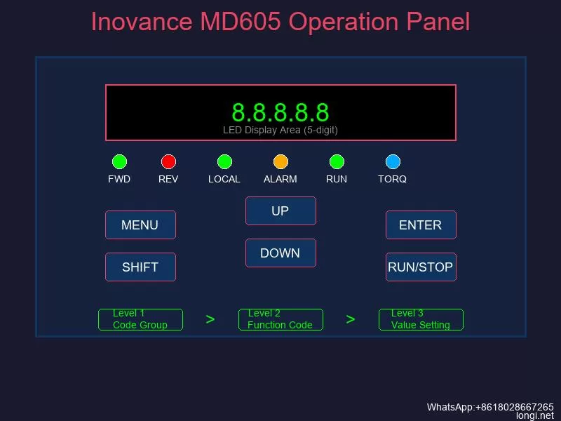
The MD605 series comes standard with an LED operation panel featuring five 8-segment LED displays and six thin-film keypad buttons. The panel is divided into three functional zones: status display area, function code display area, and keypad control area.
The five-digit LED display shows multiple types of information: set frequency, output frequency, bus voltage, output voltage, output current, output power, output torque, DI input status, DO output status, AI1 voltage value, and fault codes. Status indicators on the panel show running direction (FWD/REV), local/remote mode, torque control mode, alarm status, and running status.
The panel supports a three-level menu structure for parameter configuration:
- Level 1: Function code group (F0, F1, A0, etc.)
- Level 2: Specific function code within the group
- Level 3: Function code value setting
When a digit is flashing in any menu level, the UP and DOWN keys modify that digit’s value, while the SHIFT key moves between digits. Pressing ENTER saves the parameter and moves to the next parameter; pressing the MENU/RETURN key aborts the current edit and returns to the previous menu.
1.2 Parameter Monitoring Configuration
The operation panel supports customizable monitoring displays through parameters A6-03, A6-04 (running state display), and A6-05 (stopped state display). Each parameter uses 16 bits to enable or disable specific monitoring values. For example, setting A6-03 bit0 to 1 displays running frequency, while bit1 shows set frequency.
The MD605 also supports two free-mapping display parameters (A6-07/A6-08 for mapping 0, A6-09/A6-10 for mapping 1), allowing any word connector value to be displayed with custom units and decimal places on the LED panel.
2. Password Setting, Elimination, and Parameter Access Restriction
2.1 Parameter Access Levels
The MD605 implements a four-tier parameter access system to protect critical settings:
| Access Level | Code | Description |
|---|---|---|
| Standard | 0 | Default level, accesses basic inverter parameters |
| Extended | 1 | Includes user customization parameters and frequency detection functions |
| Expert | 2 | Complex motor performance tuning parameters, requires password |
| Manufacturer | 3 | Password-locked, reserved for factory service only |
Current access level is displayed in parameter A0-10. The target access level is set through A0-11.
2.2 Expert Password Management
To prevent unauthorized modification of expert parameters:
Setting Expert Password:
- Navigate to parameter A0-16 (Expert Password Setting)
- Enter a non-zero value (range: 0-65535)
- The password takes effect immediately; A0-14 shows “Expert password locked”
Unlocking Expert Access:
- Switch to Extended parameter level (A0-11 = 1)
- Navigate to A0-15 (Expert Password Input)
- Enter the correct password matching A0-16
- A0-14 changes to “Expert password unlocked”
- Now set A0-11 = 2 to access Expert parameters
Password Timeout: After unlocking, Expert access automatically expires after 1 hour of inactivity. The password can also be cleared by modifying A0-16 or changing A0-11 to a lower level.
2.3 Parameter Lock Function
For complete parameter protection at the field level:
Setting Parameter Lock:
- Navigate to A0-31 (Parameter Lock Setting)
- Enter a non-zero password value (0-65535)
- All parameter menus are immediately locked
Unlocking Parameter Lock:
- Enter the correct password when prompted
- A0-30 shows “Parameter lock unlocked”
- The lock automatically re-engages after the duration set in A0-32 (default: 3600 seconds)
- Manual re-locking is possible anytime by setting A0-33 = 1
Removing Password: Set A0-31 = 0 to disable the parameter lock entirely.
3. Restoring Factory Default Settings
Parameter initialization is performed through parameter A0-00 (Parameter Initialization) with three options:
| Setting Value | Function |
|---|---|
| 1 | Restore factory parameters excluding motor parameters |
| 3 | Restore factory parameters including motor parameters |
| 503 | Restore factory parameters including motor parameters, and clear all record information |
Procedure:
- Navigate to A0-00
- Enter the desired initialization code (1, 3, or 503)
- Press ENTER to confirm
- The inverter automatically restarts with default parameters
Note: Manufacturer parameters are never restored by any initialization option. For motor parameter preservation during troubleshooting, use setting value 1.
4. External Terminal Forward/Reverse Control
4.1 Control Terminal Wiring
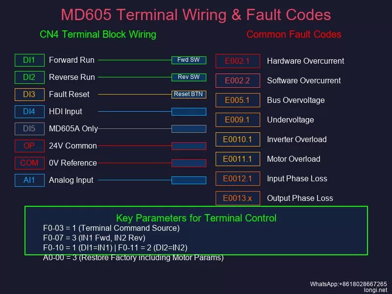
The MD605 control terminals are located on the CN4 12-pin terminal block. Key terminals for external control:
| Terminal | Name | Function |
|---|---|---|
| DI1 | Digital Input 1 | Programmable, default: Terminal Start/Stop Module A IN1 |
| DI2 | Digital Input 2 | Programmable, default: Terminal Start/Stop Module A IN2 |
| DI3 | Digital Input 3 | Programmable, default: RESET function |
| DI4 | Digital Input 4 | High-speed pulse input (HDI), max 20kHz |
| DI5 | Digital Input 5 | (MD605A model only) Programmable |
| OP | DI Power Common | Default connected to internal 24V; switch to external via S4 dip switch |
| COM | 24V Reference Ground | Isolated from GND internally |
| AI1 | Analog Input 1 | -10V to +10V or 0-20mA, 12-bit resolution |
| 10V | 10V Reference Output | 10V +/-5%, max 10mA |
| GND | Analog Ground | Isolated from COM |
| TA/TB/TC | Relay Output | Programmable relay contacts |
Wiring for External Control:
For the most common sink-type wiring using internal 24V power:
- Set S4 dip switch to the 24V position (OP connected to internal 24V)
- Connect an external controller’s 0V/GND to the inverter COM terminal
- Connect controller output signals to DI1, DI2, etc.
- When a DI terminal receives 15V-30V (via closed contact), the corresponding function activates
Important: Never short-circuit COM and OP terminals when OP is connected to internal 24V – this will damage the internal power supply.
4.2 Parameter Configuration for Forward/Reverse Control
To enable external terminal control, configure these parameters:
Step 1: Select Terminal Command Source
- Set F0-03 (Control Channel 1 Main Command Source) = 1 [Terminal]
- Alternatively, this is mapped to b1-00 with identical functionality
Step 2: Configure Terminal Mode
Set F0-07 (Terminal Start/Stop Module A Mode) according to your wiring scheme:
- 1: IN1 controls start
- 2: IN1 starts, IN2 controls direction
- 3: IN1 forward start, IN2 reverse start (most common for forward/reverse)
- 4: IN1 pulse start, IN2 stop
- 5: IN1 pulse start, IN2 stop, IN3 direction
- 6: IN1 pulse forward, IN2 pulse reverse, IN3 stop
Step 3: Assign DI Terminal Functions
- F0-10 (DI1 Terminal Function) = 1 [Terminal Module A IN1] – Forward run
- F0-11 (DI2 Terminal Function) = 2 [Terminal Module A IN2] – Reverse run / Direction
- F0-12 (DI3 Terminal Function) = 9 [Fault Reset] – Optional reset function
Example: Independent Forward/Reverse Control
For the most straightforward two-wire forward/reverse setup:
- F0-03 = 1 (Terminal command source)
- F0-07 = 3 (IN1 forward, IN2 reverse)
- F0-10 = 1 (DI1 = IN1, forward start)
- F0-11 = 2 (DI2 = IN2, reverse start)
- Wire controller forward contact to DI1-COM
- Wire controller reverse contact to DI2-COM
- Ensure both contacts use the same COM reference
When DI1 receives a signal, the motor runs forward. When DI2 receives a signal, the motor runs reverse. If both signals are active simultaneously, the inverter determines priority based on internal logic.
5. Fault Codes and Troubleshooting
The MD605 uses a three-segment fault code format: E-XXX.Y where E indicates fault severity, XXX is the main code, and Y is the sub-code.
5.1 Overcurrent Faults
E002.1 – Hardware Overcurrent
Triggered when instantaneous output current exceeds 4.24 times the inverter rated current (A3-03).
Causes and Solutions:
- Output ground fault: Measure output terminal-to-ground impedance with a megohmmeter; should be mega-ohm level. Replace grounded motor or cable.
- Output phase short: Measure UV, VW, WU resistance with multimeter; values should be symmetrical. Replace shorted components.
- Speed loop parameters too aggressive (SVC): Reduce speed loop Kp (F2-02) by half, set Ti (F2-03) to 2s. Test and repeat if needed.
- Synchronous motor demagnetization: Record back-EMF (F1-12), perform dynamic identification (F1-69=12), compare new value. Analyze root cause before replacing motor.
- Unidentified motor parameters (SVC): Perform accurate parameter identification per manual procedures.
- High carrier frequency needed: For high-speed motors, ensure carrier frequency > 12 x output frequency. Increase A5-01 if necessary.
- Motor rotating at startup: Enable speed tracking startup (d0-02 = 1).
- V/f oscillation: Adjust V/f oscillation suppression gain (d2-23), or switch to SVC control (F0-01 = 0).
E002.2 – Software Overcurrent
Triggered when current exceeds the custom software overcurrent point (A3-54).
Additional causes include:
- Overcurrent suppression misconfigured: Check d2-26=1, adjust d2-27, d2-28, d2-29
- Torque boost too high: Reduce manual torque boost (d2-14), perform static identification (F1-69=1)
- Acceleration/deceleration time too short: Extend ramp times (F0-48, F0-49)
- V/f curve voltage excessive: Reduce voltage/frequency ratio in multi-point V/f settings
5.2 Overvoltage Faults
E005.1 – Bus Overvoltage
Triggered when DC bus voltage exceeds the overvoltage activation point (A3-58).
Causes and Solutions:
- Insufficient braking power: Extend deceleration time, increase braking resistor power, enable overvoltage suppression (d1-54=1 for non-hoisting loads)
- Load dump causing overshoot: Increase speed loop Kp (F2-02), set Ti (F2-03) to 2s, enable S-curve (b7-00=1)
- Deceleration time too short: Extend F0-49 (ramp 1 deceleration time), add braking resistor if needed
- Input voltage too high: Verify input voltage is within rated range (380V-480V for 380V class, 220V-240V for 220V class)
- Braking unit voltage set too high: Lower braking unit activation voltage (A4-00) if needed
E005.2 – Overvoltage Suppression Active
System-level warning; contact technical support if persistent.
5.3 Undervoltage Faults
E009.1 – Undervoltage Fault
Triggered when DC bus voltage falls below the undervoltage activation point (A3-56).
Causes and Solutions:
- Input phase loss: Measure RS, ST, RT line voltages with multimeter AC mode; check for symmetry. Inspect input switches, contactors, and terminals.
- Grid voltage dip (most common cause): Enable undervoltage suppression (d1-63=1) for fan/pump/compressor loads. The inverter converts motor kinetic energy to electrical energy to maintain bus voltage.
- Input voltage too low: Increase input voltage to rated range, ensure upstream breakers/contactors are closed and functional.
- Undervoltage suppression parameters incorrect: Adjust undervoltage suppression Kp/Ki (d1-66/67). Start with smaller values and increase if ineffective.
- Motor oscillation causing undervoltage: Resolve motor oscillation issues by adjusting control parameters.
E009.2 – Undervoltage Suppression Active
System-level warning indicating active suppression. Hardware fault requires technical support.
E009.3 – Pre-Drive Timeout
Bus voltage remains below undervoltage point after startup command within timeout period.
- Check input wiring per manual diagrams
- Verify input voltage is within specification
- If input is confirmed correct, hardware damage likely – contact technical support
5.4 Overload Faults
E0010.1 – Inverter Overload
Inverter cumulative overload coefficient (LC-32) reaches 100%.
Causes and Solutions:
- Load too heavy or motor blocked: Check if load is abnormally heavy, verify brake is releasing properly
- For asynchronous motors at low/mid speed: Increase no-load current (F1-30), decrease mutual inductance (F1-28), maintain their product constant
- For synchronous motors at low/mid speed: Increase MTPA adjustment coefficient (d5-29) for salient-pole motors
- High-speed weak magnetic zone overload: Increase modulation index (A5-06), keep below 108%
- V/f acceleration time too short: Extend F0-48/49, enable overcurrent suppression (d2-26=1)
- Motor parameter error: Verify motor nameplate matches F1-00 through F1-11 settings
- Inverter undersized: Recalculate load requirements and select larger inverter if necessary
E0011.1 – Motor Overload
Motor cumulative overload coefficient (LC-33) reaches 100%.
- Verify load is not mechanically overloaded
- Check motor overload protection coefficient (d1-46); increase if actual motor temperature is low but fault persists
- Confirm motor parameters match nameplate data
- Verify input voltage is within specification
- For prolonged overload, consider upsizing motor or inverter
5.5 Phase Loss Faults
E0012.1 – Input Phase Loss
Detected by hardware circuit when input phase is missing.
- Verify input wiring is correct per manual
- Check input voltage is within range
- If input is confirmed correct and voltage normal, inverter diode damage likely – contact technical support
E0013.1/E0013.2/E0013.3 – U/V/W Phase Loss
Running current in one phase is significantly lower than the other two phases.
- Check output wiring for open circuits
- Verify output contactor is closed (not tripped)
- Test motor: check for line breaks, measure UV/UW/VW resistances for balance
- If resistances are unbalanced, repair or replace motor
5.6 Fault Reset Methods
After resolving the root cause, reset the fault using one of these methods:
- DI Terminal Reset: Configure any DI terminal (E0-00 through E0-04) to function 9 [Fault Reset], then activate that terminal
- Panel Reset: Press the RUN/STOP key on the LED panel while in fault state
- Power Cycle: Disconnect main power, wait until display goes dark, then reconnect power
- Communication Reset: When in communication control mode (b1-00=2), write value “16” (bit4 fault reset command) to communication address 7321H
For persistent or unclear faults, do not attempt internal repairs. Contact Inovance technical support or an authorized distributor for professional assistance.
This guide provides the essential procedures for operating the Inovance MD605 series inverter safely and effectively. Always follow safety precautions, verify wiring before energizing, and perform parameter identification when using vector control modes for optimal performance.