
HNC-808GCE CNC Manual Guide: Operator Panel, I/O Wiring, Servo Connection, Parameter Setup, PLC Diagnosis, G-Code Test and Fault Handling
Read the HNC-808GCE Manual as a Complete Machine System
HNC-808GCE is not just a display unit or a simple PLC. It is a CNC system for grinding-machine applications. The manual covers NC programming, coordinate systems, G/M/S/T commands, grinding cycles, macro programs, machine operation, reference return, program editing, diagnosis, I/O, RS232, bus I/O, power supply and grounding.
The most common service mistake is to focus on one alarm and ignore the relationship among CNC, I/O, servo drives, spindle drive, operator panel and PLC ladder logic. A reliable troubleshooting order is: power and emergency stop first, CNC status second, I/O state third, servo ready and alarm chain fourth, CNC parameters and PLC program last.
This guide turns the manual into a practical field procedure: panel operation, wiring and servo connection, low-level parameter setup, simple PLC diagnosis, G-code verification and fault handling.
Operator Panel: Read Status Before Running a Program
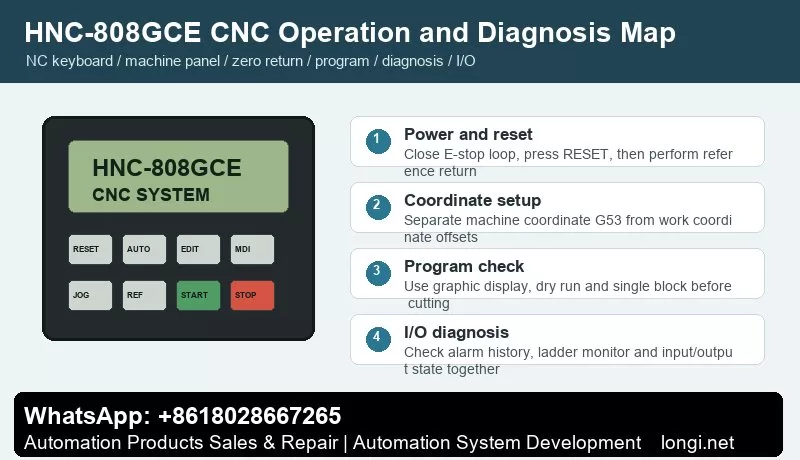
The HNC-808GCE operating station normally includes a display, NC keyboard, machine control panel and optional handwheel unit. The display is used for coordinates, program text, graphics, alarms, ladder monitor and I/O state. The NC keyboard is used for menu navigation, editing, parameter setting and diagnosis. The machine panel handles cycle start, feed hold, emergency stop, mode selection, override, spindle and coolant functions.
After power-on, do not press cycle start immediately. Check whether the system has booted normally, the emergency stop circuit is released, servo drives are ready and each axis has completed reference return if required. Reset is not a substitute for fault removal. If an E-stop input, servo alarm or limit input is still active, repeated reset only hides useful diagnostic information.
Reference return must be separated from work offset setting. Machine coordinate is the basis for travel limits and reference position; work coordinate is used by the machining program. The manual covers G53 machine coordinate, work coordinate, programming zero, G90/G91 absolute and incremental commands and G17/G18/G19 plane selection. For service work, observe reference switch and deceleration switch states in diagnosis before moving the axis.
Before actual grinding, use three checks: graphic display to inspect path direction and travel range, dry run with low override, and single-block execution to verify M-code actions such as spindle, coolant, wheel dressing, clamping and interlocks.
I/O Wiring and Servo Connection
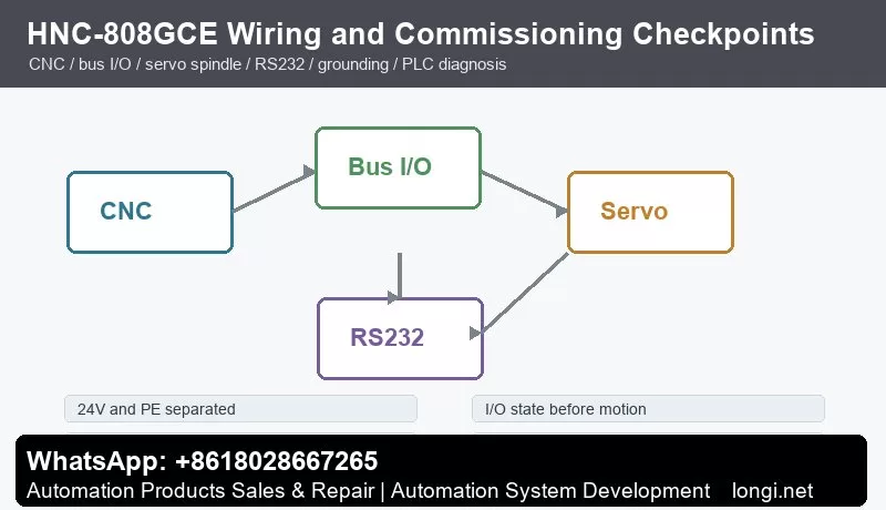
The connection section of the manual covers integrated wiring, bus I/O, power supply, grounding, RS232 and links between CNC and bus I/O units. In the cabinet, wiring can be divided into four groups: system power and grounding, operator-panel I/O, servo and spindle interfaces, and communication/remote I/O.
Power wiring must separate 24 V, 0 V, PE and shield grounding. If sensors, relays, servo enable circuits and I/O modules share one supply, verify current capacity and common return paths. Encoder cables, analog signals and motor power cables should not be bundled together. Intermittent alarms, position jumps and communication errors often come from grounding or shielding rather than from CNC parameters.
I/O diagnosis should be based on the CNC diagnosis screen. Emergency stop, cycle start, feed hold, door switch, lubrication pressure, hydraulic pressure, limit switch, reference switch, servo ready and spindle ready should all change state on the CNC display. Measuring 24 V with a meter is not enough; the CNC internal state must change as well.
Servo connection normally includes command or bus communication, enable, alarm, ready signal, encoder feedback and motor power. For bus servo systems, station number, axis number and servo parameters must match the CNC configuration. For pulse or analog interfaces, confirm direction polarity, pulse type, enable logic, alarm contact type and shield grounding. For spindle drives, also check spindle enable, forward/reverse, speed reference, speed-arrival signal, alarm and brake logic.
Low-Level Parameter Setup
Before any repair, retrofit or board replacement, back up CNC parameters and PLC data. At minimum, record system model, software version, number of axes, pulse equivalent or bus configuration, servo model, spindle configuration, I/O assignment, soft limits, reference direction, reference speed, backlash compensation, pitch compensation, work offsets and macro variables.
Treat parameters in layers. The first layer is safety: emergency stop, limits, soft limits, reference direction, travel range and servo-alarm handling. The second layer is motion: axis direction, speed, acceleration/deceleration, interpolation and following-error limits. The third layer is process: spindle, wheel dressing, coolant, clamping and lubrication. The fourth layer is communication and expansion: RS232, DNC, USB, bus I/O and remote I/O.
After restoring parameters, do not run a production program immediately. Boot the CNC, confirm keyboard and display, check emergency stop and reset, observe I/O state, return each axis to reference, jog at low speed, test spindle and M-code actions, and then dry-run a simple program.
Simple PLC Diagnosis and Editing Logic
The manual highlights alarm display, alarm history, ladder monitor, input/output and status display. A service engineer does not need to rewrite the whole PLC, but must understand input contacts, output coils, internal relays, timers, interlocks and alarm conditions.
A practical PLC logic chain is: input condition, internal permission, output action, feedback confirmation and alarm handling. For coolant, an M08 command should check E-stop, door, level and other permissions before enabling the coolant output; if pressure feedback is missing within the allowed time, the PLC should generate an alarm. For hydraulic clamping, the clamp output should wait for clamp-confirm feedback before allowing spindle and feed motion.
Never bypass emergency stop, limit or servo-alarm signals as a permanent solution. Temporary jumper tests may be used only for diagnosis in a safe stopped condition, and the real safety chain must be restored before trial running.
G-Code Test Programs for Commissioning
The programming part of the manual covers G00, G01, G02/G03, G04, G17/G18/G19, G90/G91, G20/G21, G53, M98, G65, M commands, S/T commands and grinding-related cycles. In service work, short test programs are more valuable than complex production programs.
Use a simple linear-axis program to verify coordinate direction and feed. Use a low feed rate, G90 absolute mode and a small travel range. For arc interpolation, confirm the correct plane with G17, G18 or G19 before running. For M-code tests, run spindle forward, reverse, stop, coolant on/off, clamp and unclamp separately while watching PLC outputs and feedback inputs.
Grinding machines require special attention to wheel dressing, feed hold, optional stop, single block and restart after interruption. After wheel dressing, verify compensation, coordinate update and dresser limit signals. First dry-run the path, then run low-speed motion without workpiece, and only then start actual grinding.
Common Faults and Diagnostic Handling
No display or no boot: check incoming power, UPS or switching power supply, 24 V supply, fuses, grounding and display cable. If the fan runs but the screen is dark, check the display link and IPC unit.
E-stop or external alarm remains after reset: inspect diagnosis I/O for E-stop, door, hydraulic pressure, lubrication, servo alarm and spindle alarm. Do not rely only on the physical button position.
Reference return fails: check reference mode, direction, deceleration switch, reference switch, servo enable, axis limit and reference speed. If motion direction is wrong, verify by low-speed jog before changing direction parameters.
Program cannot start: check auto mode, selected program, reference return completion, feed override, cycle-start input, PLC permission and unreset alarms.
Axis motion alarm or following error: check the servo drive alarm first, then motor power cable, encoder cable, brake, mechanical binding, lubrication, ball screw and load. If no-load motion is normal but loaded motion trips, focus on mechanical load, servo gain and acceleration settings.
I/O does not operate: decide whether the input is missing, PLC condition is false, or the output relay/final device is faulty. Use the diagnosis screen, ladder monitor and meter together.
RS232 or DNC communication fails: check cable type, baud rate, data bits, stop bits, parity, file name and transfer direction. USB-to-serial adapters can also cause compatibility problems on older machines.
Delivery Checklist
- Backup: CNC parameters, PLC, I/O table, compensation data and macro variables.
- Safety chain: emergency stop, door, limits, servo alarm, spindle alarm, hydraulic and lubrication signals.
- Motion chain: jog, reference return, soft limit, override, single block, dry run, pause and restart.
- Process chain: spindle, wheel dressing, coolant, clamp, unclamp, lubrication and chip removal actions.
- Records: software version, parameter version, PLC version, changes made and remaining risks.
The value of the HNC-808GCE manual is not only in listing keys and commands. It gives a complete closed loop from programming and operation to wiring and diagnosis. Follow the order of status confirmation, I/O diagnosis, servo check, parameter verification, PLC logic and program test, and most start failures, reference-return problems, I/O faults and servo alarms can be located methodically.