Posted on

GOOBELL G500 Inverter ERR29 Fault Mechanism and “Power-On Immediate Lockout (No Menu Access)” Case Study Analysis


1. Introduction: Why ERR29 Is Not Just a “Communication Fault Code”

In industrial inverter maintenance, ERR29 is often superficially categorized as a “communication fault.” However, in real-world GOOBELL G500 applications, this fault frequently represents a system-level control failure, involving:

  • Control source configuration logic
  • Communication state machine failure
  • HMI (keypad) UI access locking mechanism
  • Internal low-voltage control board instability

A typical field scenario shows the following behavior:

  • ERR29 appears immediately after power-on
  • No RUN command is required to trigger the fault
  • Fault persists even after disconnecting RS485/PLC wiring
  • Menu/parameter access is completely blocked
  • STOP/RESET cannot restore access

This indicates that the issue is no longer a simple communication wiring problem, but a control architecture-level fault state.
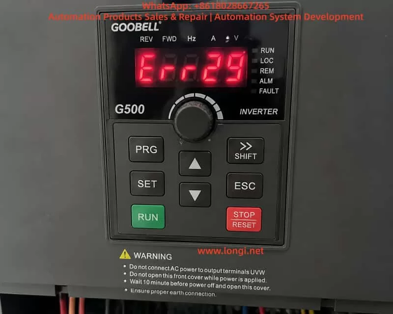

Close-up view of a GOOBELL G500 industrial frequency inverter control panel displaying an ERR29 fault code, with keypad buttons including RUN, STOP/RESET, PRG, and navigation keys, indicating a communication-related fault state on power-up.

2. Overview of GOOBELL G500 Control Architecture

To understand ERR29 correctly, the internal structure must be considered.

2.1 Power Circuit

  • Three-phase rectifier stage
  • DC bus (approx. 560–600V)
  • IGBT inverter module

2.2 Control System (Core Layer)

  • Main MCU (control logic processor)
  • PWM generation module
  • Protection detection circuits (overcurrent, overvoltage, undervoltage, overtemperature)

2.3 Human-Machine Interface (HMI)

  • Keypad panel (PRG / ENT / ESC / STOP)
  • Internal communication bus between keypad and main board

2.4 External Control Interfaces

  • RS485 Modbus communication
  • DI/DO terminal control
  • PLC remote operation signals

3. Actual Meaning of ERR29 in G500 Systems

In GOOBELL G500-type platforms, ERR29 is generally defined as:

External communication loss or invalid communication control source

However, in engineering practice, the key point is:

❗ ERR29 is not only “communication failure”, but also a “control authority loss condition”

When the drive is configured as:

  • RUN command source = COMMUNICATION (PLC/RS485)
  • Frequency reference = communication-based
  • External control enabled

If the inverter detects:

  • No valid PLC RUN command
  • Communication not established
  • Incorrect station address or baud rate

It enters:

Communication Fault Protection State (COMM FAULT LOCK)


4. Key Abnormal Symptoms in This Case

This case exhibits three critical symptoms:

4.1 ERR29 appears immediately after power-on

This indicates:

  • Fault occurs during initialization phase
  • Communication system fails at startup stage

4.2 Fault remains even after communication disconnection

This confirms:

  • External communication wiring is not the root cause
  • Internal logic state remains locked

4.3 Menu/parameter access is completely unavailable

This is the most critical symptom:

The UI system is locked at the fault display level.
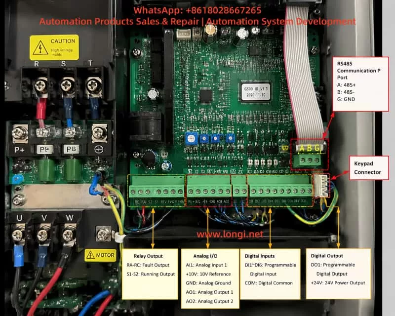

nternal view of an industrial inverter control board showing RS485 communication terminals, digital and analog I/O connectors, keypad interface cable, and main control PCB layout, illustrating signal routing and communication architecture used in VFD systems.

5. Fault Priority Lock Mechanism in G500

The GOOBELL G500 inverter uses a fault priority display system:

When communication control mode is active and communication is lost → the system enters a fault latch mode.

Characteristics:

  • Fault screen is permanently displayed (ERR29)
  • Keypad menu entry is blocked
  • RESET function is partially or fully ineffective
  • Control state machine is frozen awaiting communication recovery

6. Root Cause Analysis of This Case

Based on full isolation testing (communication removed, reset attempted, power cycling), the fault can be narrowed down to three categories:


6.1 Control Mode Latch State Not Cleared (High Probability)

If the drive is configured as:

  • Communication control mode enabled
  • PLC not responding at startup

The system enters a latched fault state where:

Even after communication is removed, the internal state remains in “waiting for communication” mode.

Result:

  • Menu access remains blocked
  • UI layer cannot be entered

6.2 Keypad-to-Mainboard Communication Failure (Medium Probability)

The keypad is not independent; it communicates with the main control board.

Possible issues:

  • Internal communication bus failure
  • Loose keypad cable connection
  • Keypad IC malfunction

Symptoms:

  • Display is normal
  • Keys are unresponsive or partially responsive
  • Menu cannot be accessed

6.3 Low-Voltage Control Power Instability (Medium-Low Probability)

Control board requires stable low-voltage rails:

  • +5V logic supply
  • +15V driver supply

If +5V is unstable:

  • MCU cannot properly execute state transitions
  • UI logic becomes frozen
  • Fault state cannot be cleared

7. Why “Communication Disconnected but Still Faulty” Is Critical

In normal communication faults:

ActionExpected Result
Disconnect RS485Fault clears
Switch to local modeMenu accessible

However, in this case:

❗ ERR29 persists even after full isolation

This indicates:

  • External control dependency has been removed
  • Internal state machine remains locked

8. Field Diagnostic Procedure (Engineering Standard)

Step 1: Full isolation of external control

  • Disconnect RS485 (A/B/SG)
  • Remove PLC control wiring
  • Keep only main power input

Step 2: Forced reset attempt

  • Hold STOP/RESET ≥ 5 seconds
  • Repeat multiple times

Step 3: UI access verification

Check if menu can be accessed:

  • PRG
  • Parameter groups
  • Monitoring mode

Step 4: Keypad function test

Test all keys:

  • STOP/RESET
  • PRG/MENU
  • ENT/ESC
  • Arrow keys

Step 5: Control voltage measurement

Measure control board supply:

  • +5V (4.8–5.1V)
  • +15V
  • Ground stability

9. Fault Classification Model

Level 1: External communication issue

✔ Already excluded

Level 2: Control mode latch state

✔ Most likely cause

Level 3: Keypad/HMI communication fault

✔ Possible

Level 4: Main control board hardware fault

✔ Requires confirmation


10. Recommended Repair Strategy

Option 1: Fast recovery method

  • Disconnect communication wiring
  • Switch to local control mode
  • Perform forced reset

Applicable only if menu access is possible


Option 2: Module replacement test (recommended)

  • Replace keypad panel
  • Cross-test UI functionality

Option 3: Mainboard-level diagnosis

  • Check +5V logic supply
  • Verify MCU operation
  • Inspect EEPROM/state memory lock

11. Key Engineering Insights

This case highlights an important field principle:

ERR29 on GOOBELL G500 is not always a simple communication fault; when accompanied by “no menu access,” it often indicates an internal control-state lock condition rather than an external wiring issue.

Key takeaways:

  1. ERR29 is a system-level fault, not only communication-related
  2. “No menu access” is more critical than the fault code itself
  3. Disconnecting communication without recovery indicates internal logic lock
  4. Diagnosis must shift from external wiring to internal control state

12. Conclusion

The GOOBELL G500 ERR29 “power-on immediate lockout with no menu access” case represents a multi-layer control system failure involving:

  • Communication control configuration
  • Internal fault latch mechanism
  • UI access restriction logic
  • Possible keypad or control board communication failure

The resolution is not limited to parameter adjustment, but requires a structured approach:

  • Control source recovery
  • Fault latch clearing
  • UI communication restoration
  • Hardware validation when necessary
Posted on

Mitsubishi FR-A740 Inverter E.UVT Undervoltage False Alarm Mechanism Analysis and Power Detection System Fault Localization Method (Based on 570V DC Bus Case Study)

1. Introduction: Engineering Significance of E.UVT Alarms and Misjudgment Phenomenon

In industrial inverter systems, undervoltage protection (UVT – Undervoltage Trip) is one of the most fundamental protection mechanisms, but also one of the most frequently misdiagnosed faults. For the Mitsubishi FR-A740 series vector control inverter, the E.UVT alarm is designed to protect the IGBT power module and control circuits from abnormal operation under insufficient DC bus voltage conditions.

However, in real-world maintenance cases, a typical contradiction often occurs:

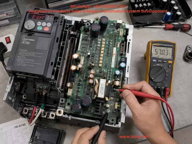
The DC bus voltage is normal (e.g., 540–580V), yet the inverter still reports an E.UVT fault.

This document analyzes a real engineering case (380V input, 570V DC bus normal, persistent E.UVT alarm) and provides a systematic breakdown of the fault mechanism across three layers: power architecture, detection circuit, and control logic, along with a practical troubleshooting methodology.


Technician diagnosing a Mitsubishi FR-A740 7.5kW inverter with E.UVT undervoltage alarm using a digital multimeter measuring 570V DC on the power/control board inside an open drive cabinet during industrial maintenance.

2. Power System Architecture and UVT Trigger Logic in FR-A740

2.1 Main Circuit Structure

The FR-A740 power path is structured as follows:

Three-phase 380–480VAC input
        ↓
Rectifier bridge (6-pulse conversion)
        ↓
DC bus capacitor bank (DC LINK ~510–580V)
        ↓
Pre-charge resistor + bypass relay
        ↓
IGBT inverter module

Under normal conditions:

ParameterNormal Range
AC Input380–480V
DC Bus510–580V
UVT Threshold~380–400V

2.2 UVT Is Not a Direct Voltage Measurement

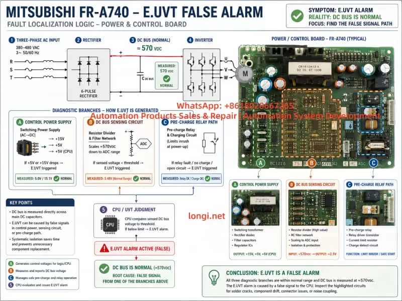
The E.UVT fault is not triggered by a single ADC measurement of DC voltage. Instead, it is determined by a combination of multiple system signals:

  1. DC bus divided voltage sensing signal
  2. Control power supply stability (SMPS output)
  3. CPU power-on initialization status (Power Good signal)

Therefore:

UVT ≠ Simple undervoltage detection
UVT = Power system instability or incomplete initialization


3. Engineering Contradiction in This Case

Observed parameters:

  • Input: 380V normal
  • DC bus: 570V normal
  • Fault: Persistent E.UVT alarm
  • Power board: Already inspected with visible aging signs

Key contradiction

If UVT were truly valid, the DC bus voltage should be below ~400V.
However, the measured value is 570V.

Therefore:

The fault is not in the power circuit, but in the detection or control circuit layer.


4. Four Primary Failure Mechanism Models of E.UVT Misalarm


4.1 Control Power Supply Transient Drop Model (Highest Probability)

Structure

The internal SMPS provides:

  • +5V CPU logic supply
  • +15V gate drive supply
  • -15V analog supply (in some versions)

Failure mechanism

When the following occurs:

  • Electrolytic capacitor degradation
  • Startup instability of SMPS
  • Instantaneous load surge

The system experiences:

At power-up:
DC BUS = normal
BUT
5V supply drops momentarily (milliseconds)

CPU logic response:

“Control power not ready → system abnormal → UVT triggered”


Typical characteristics

  • Fault appears immediately at power-on
  • DC voltage remains stable
  • Restart does not resolve issue
  • Common in aged units

4.2 DC Bus Voltage Sensing Drift Model

Structure

DC sensing path:

DC BUS → High-voltage resistor divider → Isolation optocoupler → ADC input

Failure mechanism

Common issues include:

  • Resistor drift under high voltage stress
  • Micro-cracks in solder joints
  • Optocoupler degradation (CTR drop)

Result:

Actual DC = 570V
Detected value = falsely low

CPU misinterprets:

“DC bus undervoltage → UVT trigger”


Typical characteristics

  • Intermittent fault
  • Temperature-sensitive behavior
  • DC voltage appears normal externally

Technical infographic explaining Mitsubishi FR-A740 E.UVT false alarm mechanism, showing power flow from 380V AC input to 570V DC bus, and diagnostic branches including control power supply, DC bus sensing circuit, and pre-charge relay path leading to CPU undervoltage judgment.

4.3 Pre-charge Circuit Abnormality Model

Structure

AC input → Pre-charge resistor → DC bus capacitors
                         ↓
                Bypass relay short-circuit

Failure mechanism

If the relay:

  • Fails to close
  • Has oxidized contacts
  • Has unstable drive signal

Then:

  • DC bus may still measure normally
  • But system logic detects “incomplete power establishment”

Result:

UVT triggered due to incomplete DC stabilization


4.4 Control Board Logic / EEPROM Abnormality Model

Structure

Core components:

  • MCU control CPU
  • EEPROM parameter storage
  • Power-on initialization logic

Failure mechanism

  • Corrupted EEPROM data
  • Faulty initialization sequence
  • Electrical noise interference

Result:

System interprets:
Power status = invalid
→ UVT triggered

5. Power Board Structure Analysis (Based on Field Images)

The inspected board contains three critical functional zones:

5.1 Switching Power Supply Section

Features:

  • High-frequency transformer
  • Multiple electrolytic capacitors
  • PWM control IC

Function:

  • Generates +5V / +15V / control voltages

👉 Most critical failure region


5.2 DC Voltage Sensing Circuit

Features:

  • High-value resistor networks
  • Optocoupler isolation
  • Analog feedback paths

Function:

  • DC bus voltage monitoring

👉 Primary source of false UVT detection


5.3 Relay and Drive Section

Features:

  • Power relay
  • Driver transistors / ICs
  • RC snubber circuits

Function:

  • Pre-charge bypass control

6. System-Level Fault Localization Method


Step 1: Verify Actual DC Stability

Use:

  • Multimeter with MIN/MAX function or oscilloscope

Goal:

Detect transient voltage drops


Step 2: Check Control Power Supplies

Measure:

  • +5V
  • +15V

Decision:

ConditionConclusion
StablePower board likely OK
DropsPower board failure

Step 3: Observe Relay Operation

Check:

  • Audible relay click
  • Delay or abnormal switching behavior

Step 4: Validate DC Sensing Signal

Measure:

  • Divider node voltage
  • Compare with theoretical ratio

Step 5: Replacement Verification

Fastest industrial method:

  • Swap power board
  • Or swap control board

7. Most Probable Root Cause in This Case

Based on combined evidence:

Probability ranking

Failure ModeProbability
SMPS transient instability★★★★★
DC sensing network drift★★★★
Pre-charge relay issue★★★
Control board logic fault★★

8. Engineering Maintenance Strategy Summary

For FR-A740 E.UVT false alarms:

Core principle

It is not a voltage shortage problem, but a power system initialization problem.


Repair priority

  1. Replace electrolytic capacitors in power supply section
  2. Inspect resistor divider network
  3. Check relay contacts and operation
  4. Verify control power stability during startup

9. Engineering Conclusion

The E.UVT false alarm in FR-A740 systems is fundamentally a “power system integrity and timing failure” rather than a true undervoltage condition. Correct diagnosis requires shifting from static DC voltage measurement to dynamic power-up behavior analysis.


10. Final Note

In industrial inverter maintenance practice:

UVT alarm does NOT necessarily indicate undervoltage
It often indicates power sequencing instability or signal misinterpretation


Posted on

Danfoss Holip HLP-P Series User Manual Guide: Panel Operation, Parameter Backup, Terminal Forward Reverse Control, Potentiometer Reference and Fault Handling

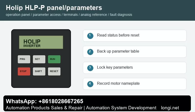
Holip HLP-P panel operation and parameter backup

Danfoss Holip HLP-P Series User Manual Guide: Panel Operation, Parameter Backup, Terminal Forward Reverse Control, Potentiometer Reference and Fault Handling

Manual Reading Method

Holip HLP-P panel operation and parameter backup

The Holip HLP-P inverter is used on fans, pumps, conveyors, packaging machines, textile equipment and general speed-control machinery. Do not read the manual as a random parameter list. Use it as a commissioning map: panel status, parameter access, run command, speed reference, protection limits and fault record.

Different HLP models use different parameter numbers, so the exact code must be checked in the model-specific manual. The working logic is similar: the run command comes from keypad, terminals or communication; the speed reference comes from keypad, potentiometer, analog signal or bus; direction is decided by reverse input or direction command; protection depends on motor data, current limit, voltage, temperature and external interlock.

Operation Panel

The common keypad includes PRG/ESC, SET/ENTER, RUN, STOP/RESET, SHIFT, UP and DOWN keys with LED or LCD display. Before editing, read frequency, current, DC bus voltage, direction, terminal state and fault code. Do not restore factory defaults before recording the original parameters, because many machines contain application-specific settings.

Record motor rated power, voltage, current, frequency and speed. Then record command source, frequency source, acceleration time, deceleration time, maximum frequency, minimum frequency, stop mode, terminal functions, analog input type and fault action. If the model supports parameter upload/download with a copy keypad, back up the parameters first. If not, photograph the key parameter pages.

Parameter Copy, Access Restriction and Unlocking

Some HLP models support parameter transfer through an external keypad or copy unit. Stop the drive first, upload parameters to the keypad, then download them to a compatible replacement drive. If the rating, voltage class or software version is different, do not copy everything blindly. Recheck motor current, overload protection, maximum frequency, carrier frequency, braking and analog scaling.

Access restriction prevents wrong edits on site. Protect motor data, terminal functions, analog input type, maximum frequency, communication address and protection parameters. Operators should only start, stop, reset and view status. If the drive is locked, obtain the valid password or original commissioning record. If initialization is unavoidable, back up all readable parameters first.

External Forward/Reverse Terminal Control

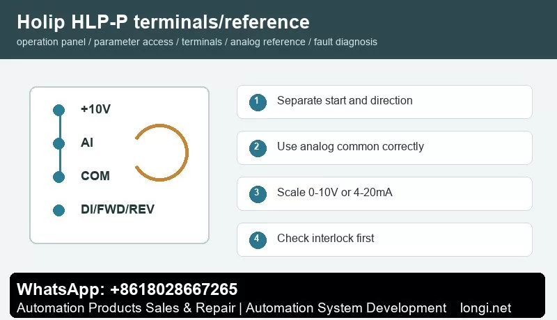
Holip HLP-P terminal control and potentiometer reference

Before terminal control, confirm control supply, common terminal and input logic. A practical method is to use one digital input for start and another for reverse or direction selection. Buttons, selector switches, relays or PLC outputs may be used, but external power and the internal 24 V supply must not be mixed without a correct common reference.

Test with the motor unloaded or at low speed. First check the main circuit and motor insulation, then power on and observe terminal state on the keypad. Set one input as run command and another as reverse. Confirm that emergency stop, external fault, thermal relay, door switch and other interlocks are closed before running.

Potentiometer and Analog Speed Reference

A potentiometer normally uses three wires: +10 V to one end, analog common to the other end and the wiper to analog voltage input. If the site uses 4-20 mA pressure, temperature, tension or flow signal, select current input and scale low and high values according to the sensor range. Use shielded cable and keep analog wiring away from motor cables and contactor coils.

The key settings are reference source, analog input type, low scaling and high scaling. If the motor still runs at minimum potentiometer position, check minimum frequency and low scaling. If it cannot reach the target frequency, check maximum frequency and high scaling. If the speed fluctuates, check common terminal, shield grounding, potentiometer quality and analog filtering.

Fault Codes and Troubleshooting

  • Overcurrent/OC: acceleration too short, jammed load, motor short, output ground fault or power module issue. Extend acceleration and test without load first.
  • Overvoltage/OV: deceleration too short, high inertia, brake resistor or brake unit fault, or high mains voltage.
  • Undervoltage/LU: low input voltage, contactor drop-out, rectifier issue or aging DC link capacitors.
  • Overload/OL: incorrect motor data, long-term overload, poor cooling or mechanical resistance.
  • Overtemperature/OH: blocked fan, dirty heatsink, high ambient temperature or insufficient installation clearance.
  • Ground Fault/Short Circuit: wet motor winding, damaged output cable, contaminated terminals or burned contactor.
  • External Fault: emergency stop, safety door, thermal relay, pressure switch or host interlock is open.
  • Communication Fault: address, baud rate, parity, protocol or shield grounding mismatch.

Delivery Checklist

After repair, do not only check whether the motor rotates. Record final parameters, terminal wiring, frequency range, direction logic, alarm history, password policy and backup method. Keep both a paper parameter sheet and electronic photos for future replacement of inverter, keypad or control board.

Posted on

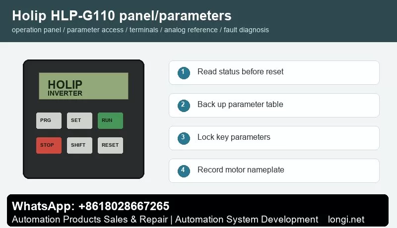
Danfoss Holip HLP-G110 Series User Manual Guide: Panel Operation, Parameter Backup, Terminal Forward Reverse Control, Potentiometer Reference and Fault Handling

Holip HLP-G110 panel operation and parameter backup

Danfoss Holip HLP-G110 Series User Manual Guide: Panel Operation, Parameter Backup, Terminal Forward Reverse Control, Potentiometer Reference and Fault Handling

Manual Reading Method

Holip HLP-G110 panel operation and parameter backup

The Holip HLP-G110 inverter is used on fans, pumps, conveyors, packaging machines, textile equipment and general speed-control machinery. Do not read the manual as a random parameter list. Use it as a commissioning map: panel status, parameter access, run command, speed reference, protection limits and fault record.

Different HLP models use different parameter numbers, so the exact code must be checked in the model-specific manual. The working logic is similar: the run command comes from keypad, terminals or communication; the speed reference comes from keypad, potentiometer, analog signal or bus; direction is decided by reverse input or direction command; protection depends on motor data, current limit, voltage, temperature and external interlock.

Operation Panel

The common keypad includes PRG/ESC, SET/ENTER, RUN, STOP/RESET, SHIFT, UP and DOWN keys with LED or LCD display. Before editing, read frequency, current, DC bus voltage, direction, terminal state and fault code. Do not restore factory defaults before recording the original parameters, because many machines contain application-specific settings.

Record motor rated power, voltage, current, frequency and speed. Then record command source, frequency source, acceleration time, deceleration time, maximum frequency, minimum frequency, stop mode, terminal functions, analog input type and fault action. If the model supports parameter upload/download with a copy keypad, back up the parameters first. If not, photograph the key parameter pages.

Parameter Copy, Access Restriction and Unlocking

Some HLP models support parameter transfer through an external keypad or copy unit. Stop the drive first, upload parameters to the keypad, then download them to a compatible replacement drive. If the rating, voltage class or software version is different, do not copy everything blindly. Recheck motor current, overload protection, maximum frequency, carrier frequency, braking and analog scaling.

Access restriction prevents wrong edits on site. Protect motor data, terminal functions, analog input type, maximum frequency, communication address and protection parameters. Operators should only start, stop, reset and view status. If the drive is locked, obtain the valid password or original commissioning record. If initialization is unavoidable, back up all readable parameters first.

External Forward/Reverse Terminal Control

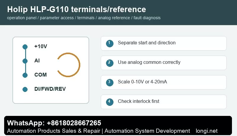
Holip HLP-G110 terminal control and potentiometer reference

Before terminal control, confirm control supply, common terminal and input logic. A practical method is to use one digital input for start and another for reverse or direction selection. Buttons, selector switches, relays or PLC outputs may be used, but external power and the internal 24 V supply must not be mixed without a correct common reference.

Test with the motor unloaded or at low speed. First check the main circuit and motor insulation, then power on and observe terminal state on the keypad. Set one input as run command and another as reverse. Confirm that emergency stop, external fault, thermal relay, door switch and other interlocks are closed before running.

Potentiometer and Analog Speed Reference

A potentiometer normally uses three wires: +10 V to one end, analog common to the other end and the wiper to analog voltage input. If the site uses 4-20 mA pressure, temperature, tension or flow signal, select current input and scale low and high values according to the sensor range. Use shielded cable and keep analog wiring away from motor cables and contactor coils.

The key settings are reference source, analog input type, low scaling and high scaling. If the motor still runs at minimum potentiometer position, check minimum frequency and low scaling. If it cannot reach the target frequency, check maximum frequency and high scaling. If the speed fluctuates, check common terminal, shield grounding, potentiometer quality and analog filtering.

Fault Codes and Troubleshooting

  • Overcurrent/OC: acceleration too short, jammed load, motor short, output ground fault or power module issue. Extend acceleration and test without load first.
  • Overvoltage/OV: deceleration too short, high inertia, brake resistor or brake unit fault, or high mains voltage.
  • Undervoltage/LU: low input voltage, contactor drop-out, rectifier issue or aging DC link capacitors.
  • Overload/OL: incorrect motor data, long-term overload, poor cooling or mechanical resistance.
  • Overtemperature/OH: blocked fan, dirty heatsink, high ambient temperature or insufficient installation clearance.
  • Ground Fault/Short Circuit: wet motor winding, damaged output cable, contaminated terminals or burned contactor.
  • External Fault: emergency stop, safety door, thermal relay, pressure switch or host interlock is open.
  • Communication Fault: address, baud rate, parity, protocol or shield grounding mismatch.

Delivery Checklist

After repair, do not only check whether the motor rotates. Record final parameters, terminal wiring, frequency range, direction logic, alarm history, password policy and backup method. Keep both a paper parameter sheet and electronic photos for future replacement of inverter, keypad or control board.

Posted on

Danfoss Holip HLP-M Series User Manual Guide: Panel Operation, Parameter Backup, Terminal Forward Reverse Control, Potentiometer Reference and Fault Handling

Holip HLP-M panel operation and parameter backup

Danfoss Holip HLP-M Series User Manual Guide: Panel Operation, Parameter Backup, Terminal Forward Reverse Control, Potentiometer Reference and Fault Handling

Manual Reading Method

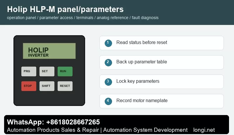
Holip HLP-M panel operation and parameter backup

The Holip HLP-M inverter is used on fans, pumps, conveyors, packaging machines, textile equipment and general speed-control machinery. Do not read the manual as a random parameter list. Use it as a commissioning map: panel status, parameter access, run command, speed reference, protection limits and fault record.

Different HLP models use different parameter numbers, so the exact code must be checked in the model-specific manual. The working logic is similar: the run command comes from keypad, terminals or communication; the speed reference comes from keypad, potentiometer, analog signal or bus; direction is decided by reverse input or direction command; protection depends on motor data, current limit, voltage, temperature and external interlock.

Operation Panel

The common keypad includes PRG/ESC, SET/ENTER, RUN, STOP/RESET, SHIFT, UP and DOWN keys with LED or LCD display. Before editing, read frequency, current, DC bus voltage, direction, terminal state and fault code. Do not restore factory defaults before recording the original parameters, because many machines contain application-specific settings.

Record motor rated power, voltage, current, frequency and speed. Then record command source, frequency source, acceleration time, deceleration time, maximum frequency, minimum frequency, stop mode, terminal functions, analog input type and fault action. If the model supports parameter upload/download with a copy keypad, back up the parameters first. If not, photograph the key parameter pages.

Parameter Copy, Access Restriction and Unlocking

Some HLP models support parameter transfer through an external keypad or copy unit. Stop the drive first, upload parameters to the keypad, then download them to a compatible replacement drive. If the rating, voltage class or software version is different, do not copy everything blindly. Recheck motor current, overload protection, maximum frequency, carrier frequency, braking and analog scaling.

Access restriction prevents wrong edits on site. Protect motor data, terminal functions, analog input type, maximum frequency, communication address and protection parameters. Operators should only start, stop, reset and view status. If the drive is locked, obtain the valid password or original commissioning record. If initialization is unavoidable, back up all readable parameters first.

External Forward/Reverse Terminal Control

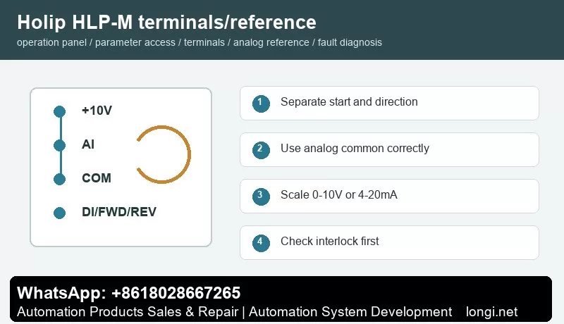
Holip HLP-M terminal control and potentiometer reference

Before terminal control, confirm control supply, common terminal and input logic. A practical method is to use one digital input for start and another for reverse or direction selection. Buttons, selector switches, relays or PLC outputs may be used, but external power and the internal 24 V supply must not be mixed without a correct common reference.

Test with the motor unloaded or at low speed. First check the main circuit and motor insulation, then power on and observe terminal state on the keypad. Set one input as run command and another as reverse. Confirm that emergency stop, external fault, thermal relay, door switch and other interlocks are closed before running.

Potentiometer and Analog Speed Reference

A potentiometer normally uses three wires: +10 V to one end, analog common to the other end and the wiper to analog voltage input. If the site uses 4-20 mA pressure, temperature, tension or flow signal, select current input and scale low and high values according to the sensor range. Use shielded cable and keep analog wiring away from motor cables and contactor coils.

The key settings are reference source, analog input type, low scaling and high scaling. If the motor still runs at minimum potentiometer position, check minimum frequency and low scaling. If it cannot reach the target frequency, check maximum frequency and high scaling. If the speed fluctuates, check common terminal, shield grounding, potentiometer quality and analog filtering.

Fault Codes and Troubleshooting

  • Overcurrent/OC: acceleration too short, jammed load, motor short, output ground fault or power module issue. Extend acceleration and test without load first.
  • Overvoltage/OV: deceleration too short, high inertia, brake resistor or brake unit fault, or high mains voltage.
  • Undervoltage/LU: low input voltage, contactor drop-out, rectifier issue or aging DC link capacitors.
  • Overload/OL: incorrect motor data, long-term overload, poor cooling or mechanical resistance.
  • Overtemperature/OH: blocked fan, dirty heatsink, high ambient temperature or insufficient installation clearance.
  • Ground Fault/Short Circuit: wet motor winding, damaged output cable, contaminated terminals or burned contactor.
  • External Fault: emergency stop, safety door, thermal relay, pressure switch or host interlock is open.
  • Communication Fault: address, baud rate, parity, protocol or shield grounding mismatch.

Delivery Checklist

After repair, do not only check whether the motor rotates. Record final parameters, terminal wiring, frequency range, direction logic, alarm history, password policy and backup method. Keep both a paper parameter sheet and electronic photos for future replacement of inverter, keypad or control board.

Posted on

Danfoss Holip HLP-SK180 Series User Manual Guide: Panel Operation, Parameter Backup, Terminal Forward Reverse Control, Potentiometer Reference and Fault Handling

Holip HLP-SK180 panel operation and parameter backup

Danfoss Holip HLP-SK180 Series User Manual Guide: Panel Operation, Parameter Backup, Terminal Forward Reverse Control, Potentiometer Reference and Fault Handling

Manual Reading Method

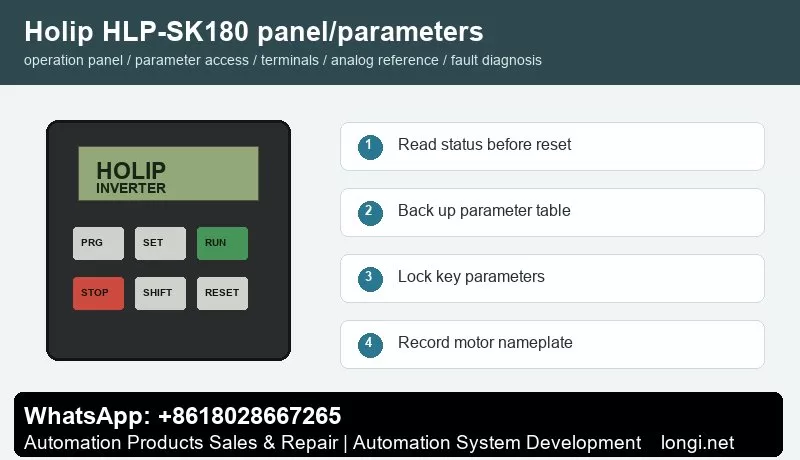
Holip HLP-SK180 panel operation and parameter backup

The Holip HLP-SK180 inverter is used on fans, pumps, conveyors, packaging machines, textile equipment and general speed-control machinery. Do not read the manual as a random parameter list. Use it as a commissioning map: panel status, parameter access, run command, speed reference, protection limits and fault record.

Different HLP models use different parameter numbers, so the exact code must be checked in the model-specific manual. The working logic is similar: the run command comes from keypad, terminals or communication; the speed reference comes from keypad, potentiometer, analog signal or bus; direction is decided by reverse input or direction command; protection depends on motor data, current limit, voltage, temperature and external interlock.

Operation Panel

The common keypad includes PRG/ESC, SET/ENTER, RUN, STOP/RESET, SHIFT, UP and DOWN keys with LED or LCD display. Before editing, read frequency, current, DC bus voltage, direction, terminal state and fault code. Do not restore factory defaults before recording the original parameters, because many machines contain application-specific settings.

Record motor rated power, voltage, current, frequency and speed. Then record command source, frequency source, acceleration time, deceleration time, maximum frequency, minimum frequency, stop mode, terminal functions, analog input type and fault action. If the model supports parameter upload/download with a copy keypad, back up the parameters first. If not, photograph the key parameter pages.

Parameter Copy, Access Restriction and Unlocking

Some HLP models support parameter transfer through an external keypad or copy unit. Stop the drive first, upload parameters to the keypad, then download them to a compatible replacement drive. If the rating, voltage class or software version is different, do not copy everything blindly. Recheck motor current, overload protection, maximum frequency, carrier frequency, braking and analog scaling.

Access restriction prevents wrong edits on site. Protect motor data, terminal functions, analog input type, maximum frequency, communication address and protection parameters. Operators should only start, stop, reset and view status. If the drive is locked, obtain the valid password or original commissioning record. If initialization is unavoidable, back up all readable parameters first.

External Forward/Reverse Terminal Control

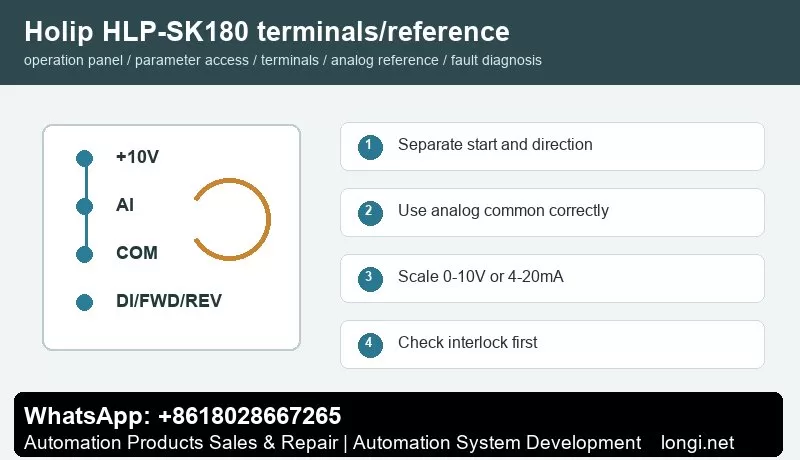
Holip HLP-SK180 terminal control and potentiometer reference

Before terminal control, confirm control supply, common terminal and input logic. A practical method is to use one digital input for start and another for reverse or direction selection. Buttons, selector switches, relays or PLC outputs may be used, but external power and the internal 24 V supply must not be mixed without a correct common reference.

Test with the motor unloaded or at low speed. First check the main circuit and motor insulation, then power on and observe terminal state on the keypad. Set one input as run command and another as reverse. Confirm that emergency stop, external fault, thermal relay, door switch and other interlocks are closed before running.

Potentiometer and Analog Speed Reference

A potentiometer normally uses three wires: +10 V to one end, analog common to the other end and the wiper to analog voltage input. If the site uses 4-20 mA pressure, temperature, tension or flow signal, select current input and scale low and high values according to the sensor range. Use shielded cable and keep analog wiring away from motor cables and contactor coils.

The key settings are reference source, analog input type, low scaling and high scaling. If the motor still runs at minimum potentiometer position, check minimum frequency and low scaling. If it cannot reach the target frequency, check maximum frequency and high scaling. If the speed fluctuates, check common terminal, shield grounding, potentiometer quality and analog filtering.

Fault Codes and Troubleshooting

  • Overcurrent/OC: acceleration too short, jammed load, motor short, output ground fault or power module issue. Extend acceleration and test without load first.
  • Overvoltage/OV: deceleration too short, high inertia, brake resistor or brake unit fault, or high mains voltage.
  • Undervoltage/LU: low input voltage, contactor drop-out, rectifier issue or aging DC link capacitors.
  • Overload/OL: incorrect motor data, long-term overload, poor cooling or mechanical resistance.
  • Overtemperature/OH: blocked fan, dirty heatsink, high ambient temperature or insufficient installation clearance.
  • Ground Fault/Short Circuit: wet motor winding, damaged output cable, contaminated terminals or burned contactor.
  • External Fault: emergency stop, safety door, thermal relay, pressure switch or host interlock is open.
  • Communication Fault: address, baud rate, parity, protocol or shield grounding mismatch.

Delivery Checklist

After repair, do not only check whether the motor rotates. Record final parameters, terminal wiring, frequency range, direction logic, alarm history, password policy and backup method. Keep both a paper parameter sheet and electronic photos for future replacement of inverter, keypad or control board.

Posted on

Danfoss Holip HLP-SP100 Series User Manual Guide: Panel Operation, Parameter Backup, Terminal Forward Reverse Control, Potentiometer Reference and Fault Handling

Holip HLP-SP100 panel operation and parameter backup

Danfoss Holip HLP-SP100 Series User Manual Guide: Panel Operation, Parameter Backup, Terminal Forward Reverse Control, Potentiometer Reference and Fault Handling

Manual Reading Method

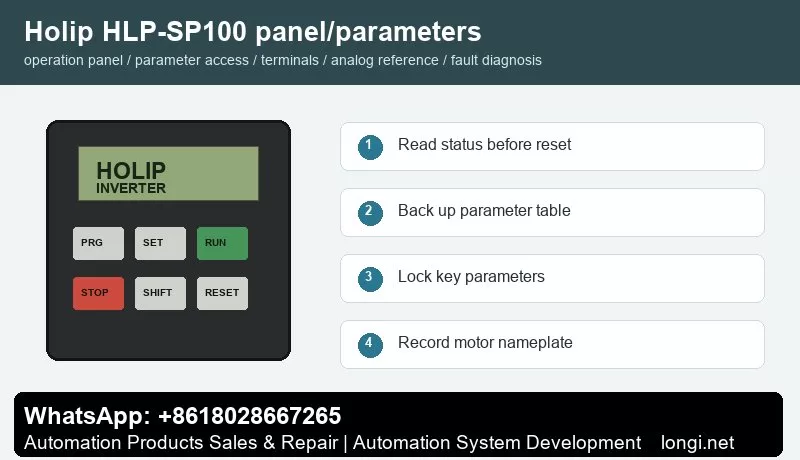
Holip HLP-SP100 panel operation and parameter backup

The Holip HLP-SP100 inverter is used on fans, pumps, conveyors, packaging machines, textile equipment and general speed-control machinery. Do not read the manual as a random parameter list. Use it as a commissioning map: panel status, parameter access, run command, speed reference, protection limits and fault record.

Different HLP models use different parameter numbers, so the exact code must be checked in the model-specific manual. The working logic is similar: the run command comes from keypad, terminals or communication; the speed reference comes from keypad, potentiometer, analog signal or bus; direction is decided by reverse input or direction command; protection depends on motor data, current limit, voltage, temperature and external interlock.

Operation Panel

The common keypad includes PRG/ESC, SET/ENTER, RUN, STOP/RESET, SHIFT, UP and DOWN keys with LED or LCD display. Before editing, read frequency, current, DC bus voltage, direction, terminal state and fault code. Do not restore factory defaults before recording the original parameters, because many machines contain application-specific settings.

Record motor rated power, voltage, current, frequency and speed. Then record command source, frequency source, acceleration time, deceleration time, maximum frequency, minimum frequency, stop mode, terminal functions, analog input type and fault action. If the model supports parameter upload/download with a copy keypad, back up the parameters first. If not, photograph the key parameter pages.

Parameter Copy, Access Restriction and Unlocking

Some HLP models support parameter transfer through an external keypad or copy unit. Stop the drive first, upload parameters to the keypad, then download them to a compatible replacement drive. If the rating, voltage class or software version is different, do not copy everything blindly. Recheck motor current, overload protection, maximum frequency, carrier frequency, braking and analog scaling.

Access restriction prevents wrong edits on site. Protect motor data, terminal functions, analog input type, maximum frequency, communication address and protection parameters. Operators should only start, stop, reset and view status. If the drive is locked, obtain the valid password or original commissioning record. If initialization is unavoidable, back up all readable parameters first.

External Forward/Reverse Terminal Control

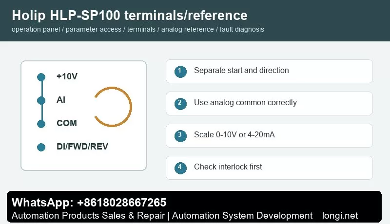
Holip HLP-SP100 terminal control and potentiometer reference

Before terminal control, confirm control supply, common terminal and input logic. A practical method is to use one digital input for start and another for reverse or direction selection. Buttons, selector switches, relays or PLC outputs may be used, but external power and the internal 24 V supply must not be mixed without a correct common reference.

Test with the motor unloaded or at low speed. First check the main circuit and motor insulation, then power on and observe terminal state on the keypad. Set one input as run command and another as reverse. Confirm that emergency stop, external fault, thermal relay, door switch and other interlocks are closed before running.

Potentiometer and Analog Speed Reference

A potentiometer normally uses three wires: +10 V to one end, analog common to the other end and the wiper to analog voltage input. If the site uses 4-20 mA pressure, temperature, tension or flow signal, select current input and scale low and high values according to the sensor range. Use shielded cable and keep analog wiring away from motor cables and contactor coils.

The key settings are reference source, analog input type, low scaling and high scaling. If the motor still runs at minimum potentiometer position, check minimum frequency and low scaling. If it cannot reach the target frequency, check maximum frequency and high scaling. If the speed fluctuates, check common terminal, shield grounding, potentiometer quality and analog filtering.

Fault Codes and Troubleshooting

  • Overcurrent/OC: acceleration too short, jammed load, motor short, output ground fault or power module issue. Extend acceleration and test without load first.
  • Overvoltage/OV: deceleration too short, high inertia, brake resistor or brake unit fault, or high mains voltage.
  • Undervoltage/LU: low input voltage, contactor drop-out, rectifier issue or aging DC link capacitors.
  • Overload/OL: incorrect motor data, long-term overload, poor cooling or mechanical resistance.
  • Overtemperature/OH: blocked fan, dirty heatsink, high ambient temperature or insufficient installation clearance.
  • Ground Fault/Short Circuit: wet motor winding, damaged output cable, contaminated terminals or burned contactor.
  • External Fault: emergency stop, safety door, thermal relay, pressure switch or host interlock is open.
  • Communication Fault: address, baud rate, parity, protocol or shield grounding mismatch.

Delivery Checklist

After repair, do not only check whether the motor rotates. Record final parameters, terminal wiring, frequency range, direction logic, alarm history, password policy and backup method. Keep both a paper parameter sheet and electronic photos for future replacement of inverter, keypad or control board.

Posted on

Danfoss Holip HLP-SK190 Series User Manual Guide: Panel Operation, Parameter Backup, Terminal Forward Reverse Control, Potentiometer Reference and Fault Handling

Holip HLP-SK190 panel operation and parameter backup

Danfoss Holip HLP-SK190 Series User Manual Guide: Panel Operation, Parameter Backup, Terminal Forward Reverse Control, Potentiometer Reference and Fault Handling

Manual Reading Method

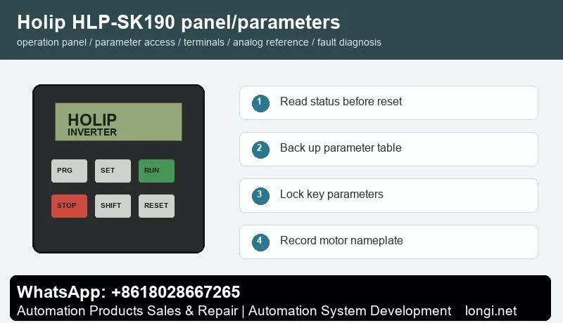
Holip HLP-SK190 panel operation and parameter backup

The Holip HLP-SK190 inverter is used on fans, pumps, conveyors, packaging machines, textile equipment and general speed-control machinery. Do not read the manual as a random parameter list. Use it as a commissioning map: panel status, parameter access, run command, speed reference, protection limits and fault record.

Different HLP models use different parameter numbers, so the exact code must be checked in the model-specific manual. The working logic is similar: the run command comes from keypad, terminals or communication; the speed reference comes from keypad, potentiometer, analog signal or bus; direction is decided by reverse input or direction command; protection depends on motor data, current limit, voltage, temperature and external interlock.

Operation Panel

The common keypad includes PRG/ESC, SET/ENTER, RUN, STOP/RESET, SHIFT, UP and DOWN keys with LED or LCD display. Before editing, read frequency, current, DC bus voltage, direction, terminal state and fault code. Do not restore factory defaults before recording the original parameters, because many machines contain application-specific settings.

Record motor rated power, voltage, current, frequency and speed. Then record command source, frequency source, acceleration time, deceleration time, maximum frequency, minimum frequency, stop mode, terminal functions, analog input type and fault action. If the model supports parameter upload/download with a copy keypad, back up the parameters first. If not, photograph the key parameter pages.

Parameter Copy, Access Restriction and Unlocking

Some HLP models support parameter transfer through an external keypad or copy unit. Stop the drive first, upload parameters to the keypad, then download them to a compatible replacement drive. If the rating, voltage class or software version is different, do not copy everything blindly. Recheck motor current, overload protection, maximum frequency, carrier frequency, braking and analog scaling.

Access restriction prevents wrong edits on site. Protect motor data, terminal functions, analog input type, maximum frequency, communication address and protection parameters. Operators should only start, stop, reset and view status. If the drive is locked, obtain the valid password or original commissioning record. If initialization is unavoidable, back up all readable parameters first.

External Forward/Reverse Terminal Control

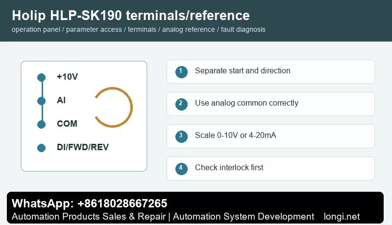
Holip HLP-SK190 terminal control and potentiometer reference

Before terminal control, confirm control supply, common terminal and input logic. A practical method is to use one digital input for start and another for reverse or direction selection. Buttons, selector switches, relays or PLC outputs may be used, but external power and the internal 24 V supply must not be mixed without a correct common reference.

Test with the motor unloaded or at low speed. First check the main circuit and motor insulation, then power on and observe terminal state on the keypad. Set one input as run command and another as reverse. Confirm that emergency stop, external fault, thermal relay, door switch and other interlocks are closed before running.

Potentiometer and Analog Speed Reference

A potentiometer normally uses three wires: +10 V to one end, analog common to the other end and the wiper to analog voltage input. If the site uses 4-20 mA pressure, temperature, tension or flow signal, select current input and scale low and high values according to the sensor range. Use shielded cable and keep analog wiring away from motor cables and contactor coils.

The key settings are reference source, analog input type, low scaling and high scaling. If the motor still runs at minimum potentiometer position, check minimum frequency and low scaling. If it cannot reach the target frequency, check maximum frequency and high scaling. If the speed fluctuates, check common terminal, shield grounding, potentiometer quality and analog filtering.

Fault Codes and Troubleshooting

  • Overcurrent/OC: acceleration too short, jammed load, motor short, output ground fault or power module issue. Extend acceleration and test without load first.
  • Overvoltage/OV: deceleration too short, high inertia, brake resistor or brake unit fault, or high mains voltage.
  • Undervoltage/LU: low input voltage, contactor drop-out, rectifier issue or aging DC link capacitors.
  • Overload/OL: incorrect motor data, long-term overload, poor cooling or mechanical resistance.
  • Overtemperature/OH: blocked fan, dirty heatsink, high ambient temperature or insufficient installation clearance.
  • Ground Fault/Short Circuit: wet motor winding, damaged output cable, contaminated terminals or burned contactor.
  • External Fault: emergency stop, safety door, thermal relay, pressure switch or host interlock is open.
  • Communication Fault: address, baud rate, parity, protocol or shield grounding mismatch.

Delivery Checklist

After repair, do not only check whether the motor rotates. Record final parameters, terminal wiring, frequency range, direction logic, alarm history, password policy and backup method. Keep both a paper parameter sheet and electronic photos for future replacement of inverter, keypad or control board.

Posted on

Danfoss Holip HLP-SK110 Series User Manual Guide: Panel Operation, Parameter Backup, Terminal Forward Reverse Control, Potentiometer Reference and Fault Handling

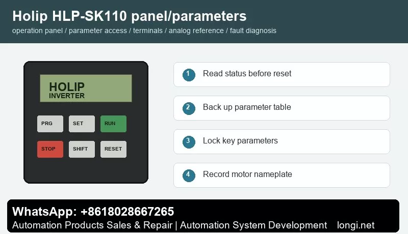
Holip HLP-SK110 panel operation and parameter backup

Danfoss Holip HLP-SK110 Series User Manual Guide: Panel Operation, Parameter Backup, Terminal Forward Reverse Control, Potentiometer Reference and Fault Handling

Manual Reading Method

Holip HLP-SK110 panel operation and parameter backup

The Holip HLP-SK110 inverter is used on fans, pumps, conveyors, packaging machines, textile equipment and general speed-control machinery. Do not read the manual as a random parameter list. Use it as a commissioning map: panel status, parameter access, run command, speed reference, protection limits and fault record.

Different HLP models use different parameter numbers, so the exact code must be checked in the model-specific manual. The working logic is similar: the run command comes from keypad, terminals or communication; the speed reference comes from keypad, potentiometer, analog signal or bus; direction is decided by reverse input or direction command; protection depends on motor data, current limit, voltage, temperature and external interlock.

Operation Panel

The common keypad includes PRG/ESC, SET/ENTER, RUN, STOP/RESET, SHIFT, UP and DOWN keys with LED or LCD display. Before editing, read frequency, current, DC bus voltage, direction, terminal state and fault code. Do not restore factory defaults before recording the original parameters, because many machines contain application-specific settings.

Record motor rated power, voltage, current, frequency and speed. Then record command source, frequency source, acceleration time, deceleration time, maximum frequency, minimum frequency, stop mode, terminal functions, analog input type and fault action. If the model supports parameter upload/download with a copy keypad, back up the parameters first. If not, photograph the key parameter pages.

Parameter Copy, Access Restriction and Unlocking

Some HLP models support parameter transfer through an external keypad or copy unit. Stop the drive first, upload parameters to the keypad, then download them to a compatible replacement drive. If the rating, voltage class or software version is different, do not copy everything blindly. Recheck motor current, overload protection, maximum frequency, carrier frequency, braking and analog scaling.

Access restriction prevents wrong edits on site. Protect motor data, terminal functions, analog input type, maximum frequency, communication address and protection parameters. Operators should only start, stop, reset and view status. If the drive is locked, obtain the valid password or original commissioning record. If initialization is unavoidable, back up all readable parameters first.

External Forward/Reverse Terminal Control

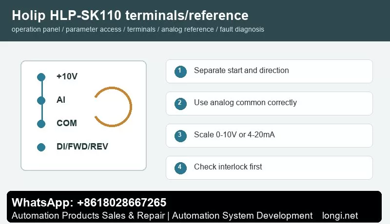
Holip HLP-SK110 terminal control and potentiometer reference

Before terminal control, confirm control supply, common terminal and input logic. A practical method is to use one digital input for start and another for reverse or direction selection. Buttons, selector switches, relays or PLC outputs may be used, but external power and the internal 24 V supply must not be mixed without a correct common reference.

Test with the motor unloaded or at low speed. First check the main circuit and motor insulation, then power on and observe terminal state on the keypad. Set one input as run command and another as reverse. Confirm that emergency stop, external fault, thermal relay, door switch and other interlocks are closed before running.

Potentiometer and Analog Speed Reference

A potentiometer normally uses three wires: +10 V to one end, analog common to the other end and the wiper to analog voltage input. If the site uses 4-20 mA pressure, temperature, tension or flow signal, select current input and scale low and high values according to the sensor range. Use shielded cable and keep analog wiring away from motor cables and contactor coils.

The key settings are reference source, analog input type, low scaling and high scaling. If the motor still runs at minimum potentiometer position, check minimum frequency and low scaling. If it cannot reach the target frequency, check maximum frequency and high scaling. If the speed fluctuates, check common terminal, shield grounding, potentiometer quality and analog filtering.

Fault Codes and Troubleshooting

  • Overcurrent/OC: acceleration too short, jammed load, motor short, output ground fault or power module issue. Extend acceleration and test without load first.
  • Overvoltage/OV: deceleration too short, high inertia, brake resistor or brake unit fault, or high mains voltage.
  • Undervoltage/LU: low input voltage, contactor drop-out, rectifier issue or aging DC link capacitors.
  • Overload/OL: incorrect motor data, long-term overload, poor cooling or mechanical resistance.
  • Overtemperature/OH: blocked fan, dirty heatsink, high ambient temperature or insufficient installation clearance.
  • Ground Fault/Short Circuit: wet motor winding, damaged output cable, contaminated terminals or burned contactor.
  • External Fault: emergency stop, safety door, thermal relay, pressure switch or host interlock is open.
  • Communication Fault: address, baud rate, parity, protocol or shield grounding mismatch.

Delivery Checklist

After repair, do not only check whether the motor rotates. Record final parameters, terminal wiring, frequency range, direction logic, alarm history, password policy and backup method. Keep both a paper parameter sheet and electronic photos for future replacement of inverter, keypad or control board.

Posted on

Danfoss Holip HLP-SJ110 Series User Manual Guide: Panel Operation, Parameter Backup, Terminal Forward Reverse Control, Potentiometer Reference and Fault Handling

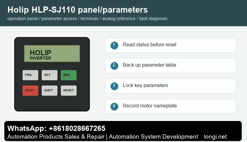
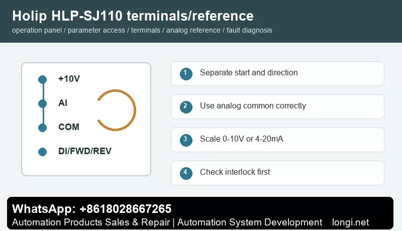
Holip HLP-SJ110 panel operation and parameter backup

Danfoss Holip HLP-SJ110 Series User Manual Guide: Panel Operation, Parameter Backup, Terminal Forward Reverse Control, Potentiometer Reference and Fault Handling

Manual Reading Method

Holip HLP-SJ110 panel operation and parameter backup

The Holip HLP-SJ110 inverter is used on fans, pumps, conveyors, packaging machines, textile equipment and general speed-control machinery. Do not read the manual as a random parameter list. Use it as a commissioning map: panel status, parameter access, run command, speed reference, protection limits and fault record.

Different HLP models use different parameter numbers, so the exact code must be checked in the model-specific manual. The working logic is similar: the run command comes from keypad, terminals or communication; the speed reference comes from keypad, potentiometer, analog signal or bus; direction is decided by reverse input or direction command; protection depends on motor data, current limit, voltage, temperature and external interlock.

Operation Panel

The common keypad includes PRG/ESC, SET/ENTER, RUN, STOP/RESET, SHIFT, UP and DOWN keys with LED or LCD display. Before editing, read frequency, current, DC bus voltage, direction, terminal state and fault code. Do not restore factory defaults before recording the original parameters, because many machines contain application-specific settings.

Record motor rated power, voltage, current, frequency and speed. Then record command source, frequency source, acceleration time, deceleration time, maximum frequency, minimum frequency, stop mode, terminal functions, analog input type and fault action. If the model supports parameter upload/download with a copy keypad, back up the parameters first. If not, photograph the key parameter pages.

Parameter Copy, Access Restriction and Unlocking

Some HLP models support parameter transfer through an external keypad or copy unit. Stop the drive first, upload parameters to the keypad, then download them to a compatible replacement drive. If the rating, voltage class or software version is different, do not copy everything blindly. Recheck motor current, overload protection, maximum frequency, carrier frequency, braking and analog scaling.

Access restriction prevents wrong edits on site. Protect motor data, terminal functions, analog input type, maximum frequency, communication address and protection parameters. Operators should only start, stop, reset and view status. If the drive is locked, obtain the valid password or original commissioning record. If initialization is unavoidable, back up all readable parameters first.

External Forward/Reverse Terminal Control

Holip HLP-SJ110 terminal control and potentiometer reference

Before terminal control, confirm control supply, common terminal and input logic. A practical method is to use one digital input for start and another for reverse or direction selection. Buttons, selector switches, relays or PLC outputs may be used, but external power and the internal 24 V supply must not be mixed without a correct common reference.

Test with the motor unloaded or at low speed. First check the main circuit and motor insulation, then power on and observe terminal state on the keypad. Set one input as run command and another as reverse. Confirm that emergency stop, external fault, thermal relay, door switch and other interlocks are closed before running.

Potentiometer and Analog Speed Reference

A potentiometer normally uses three wires: +10 V to one end, analog common to the other end and the wiper to analog voltage input. If the site uses 4-20 mA pressure, temperature, tension or flow signal, select current input and scale low and high values according to the sensor range. Use shielded cable and keep analog wiring away from motor cables and contactor coils.

The key settings are reference source, analog input type, low scaling and high scaling. If the motor still runs at minimum potentiometer position, check minimum frequency and low scaling. If it cannot reach the target frequency, check maximum frequency and high scaling. If the speed fluctuates, check common terminal, shield grounding, potentiometer quality and analog filtering.

Fault Codes and Troubleshooting

  • Overcurrent/OC: acceleration too short, jammed load, motor short, output ground fault or power module issue. Extend acceleration and test without load first.
  • Overvoltage/OV: deceleration too short, high inertia, brake resistor or brake unit fault, or high mains voltage.
  • Undervoltage/LU: low input voltage, contactor drop-out, rectifier issue or aging DC link capacitors.
  • Overload/OL: incorrect motor data, long-term overload, poor cooling or mechanical resistance.
  • Overtemperature/OH: blocked fan, dirty heatsink, high ambient temperature or insufficient installation clearance.
  • Ground Fault/Short Circuit: wet motor winding, damaged output cable, contaminated terminals or burned contactor.
  • External Fault: emergency stop, safety door, thermal relay, pressure switch or host interlock is open.
  • Communication Fault: address, baud rate, parity, protocol or shield grounding mismatch.

Delivery Checklist

After repair, do not only check whether the motor rotates. Record final parameters, terminal wiring, frequency range, direction logic, alarm history, password policy and backup method. Keep both a paper parameter sheet and electronic photos for future replacement of inverter, keypad or control board.