
GSK980TD CNC System Manual Guide: Operation Panel, Parameter Switch, PLC Diagnosis, Homing, MDI, Tool Offset, I/O and Fault Repair
What the GSK980TD Controls
GSK980TD is a lathe CNC system used on economical CNC lathes and retrofit machines. It is not only a display unit or a servo drive. It interprets machining programs, controls X/Z axis motion, handles spindle, coolant, lubrication and turret M functions, manages I/O logic, tool offsets, alarms and machine parameters.
For maintenance, judge the system as a complete chain: operation mode, parameter switch, PLC inputs and outputs, axis drive, limit switches, emergency stop, spindle control and program state. A screen without an alarm does not mean the machine is ready, and a ready servo drive does not mean the CNC conditions are satisfied.
Panel and Page Functions
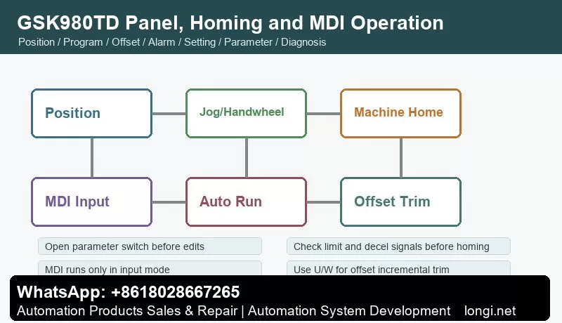
The operation panel has LCD display, edit keyboard, page keys and machine-control keys. Page keys include Position, Program, Offset, Alarm, Setting, Parameter and Diagnosis. Mode keys include Edit, Auto, MDI Input, Manual, Handwheel/Step, Program Zero Return and Machine Zero Return.
The practical diagnostic order is: check Alarm page, check Diagnosis page for I/O, confirm key parameters, observe axis status on Position page, then use Manual or MDI for low-risk movement. Direct cycle start before checking these pages can turn a simple limit or offset issue into a crash.
Parameter Switch, Password and Electronic Disk
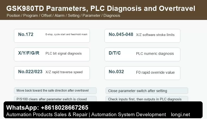
The Setting page includes parameter switch and program switch. When the parameter switch is off, system parameters cannot be modified. When it is turned on, P/S100 may appear. After setting parameters, turn the switch off again; the alarm normally clears or can be reset. Always close the parameter switch after service.
GSK980TD uses multiple password levels: system debugging, system configuration, machine builder, workshop management and operator. Low-level users cannot edit protected O9000-O9999 programs. Use the password page when protected parameters or builder programs must be modified.
The electronic disk stores state parameters, data parameters, pitch compensation and tool offsets. N0 stores factory original data, N2 servo original data, N3 stepper original data, N4 common data and N1 user data. Before large adjustments, back up working parameters to N1 or to a PC.
I/O and PLC Diagnosis
The Diagnosis page shows keyboard diagnosis, status diagnosis, PLC signal status and PLC numeric diagnosis. PLC bit signals include X0000-X0029, Y0000-Y0019, F0000-F0255, G0000-G0255, A0000-A0024, K0000-K0039 and R0000-R0999. Numeric diagnosis includes D0000-D0999, T0000-T0099 and C0000-C0099.
Use the rule: input before output, safety chain before action chain, diagnosis before rewiring. If cycle start fails, check emergency stop, feed hold, auto mode, program selection and cycle-start input first. If coolant does not work, check the internal PLC signal before checking relay output. If turret does not index, check output, in-position input and turret power.
Emergency stop can be masked by state parameter No.172 Bit3 (MESP), and external E-stop can be checked by diagnostic No.001 Bit4 (*ESP). Do not leave E-stop or limit switches bypassed after testing.
Manual, Handwheel and Homing
Manual mode supports X/Z jogging, rapid traverse, spindle control, coolant, lubrication and turret operation. Data parameters No.022 and No.023 set X/Z rapid speeds. No.032 sets the F0 rapid override. After repair, use low rapid override first and verify direction, limit switches and mechanical clearance.
Handwheel/step mode is selected by state parameter No.001 Bit3. Select X or Z axis and choose handwheel magnification. The manual warns that handwheel rotation should be below 5 revolutions per second; otherwise actual movement may not match scale marks.
Zero return includes program zero return and machine zero return. Machine zero return depends on the installed deceleration switch, one-revolution signal or Hall switch. If the machine has no reference switch, do not use machine zero return. Check return direction, decel switch, limit switch, servo ready and E-stop before homing.
MDI and Automatic Run
MDI can run one command block, such as G50, G00, G01, M03, M05, M08, M09, S and T commands. MDI runs only in input mode. Use it to test spindle, coolant, turret and short low-speed movement, but do not treat MDI as a full replacement for dry run and single-block verification.
Before automatic running, confirm the program, current coordinate, work offset, tool offset, spindle state and modal G/M/S/T conditions. When starting from a middle block, use MDI to restore required modal states first.
Tool Offset and Tool Setting
The Offset page modifies X/Z offset values. Absolute input uses X or Z. Incremental trim uses U or W. For example, input U0.001 to increase X offset by 0.001 mm. When the origin of an offset is unclear, avoid rewriting absolute X/Z values; use small U/W trims and record before/after values.
GSK980TD supports fixed-point tool setting, trial-cut tool setting, machine-zero tool setting and tool setting with compensation. Tool setting with compensation requires state parameter No.005 Bit1 (PPD). Direct measured offset input depends on state parameter No.012 Bit5 (DOFSI).
Common G Codes and Auxiliary Functions
Common lathe commands include G00 rapid positioning, G01 linear interpolation and G50 coordinate setting. Common M functions include M03 spindle forward, M04 spindle reverse, M05 spindle stop, M08 coolant on and M09 coolant off. Actual spindle speed display requires a spindle encoder.
If M03 is issued but the spindle does not rotate, separate CNC M-output, spindle inverter/servo enable, analog command, forward/reverse terminals and spindle override. If only speed display is missing, check spindle encoder feedback and related parameters.
Overtravel and Safety Alarms
GSK980TD uses hardware overtravel switches and software stroke limits. Software travel range is set by data parameters No.045, No.046, No.047 and No.048 for X/Z positive and negative limits. After overtravel, move manually toward the safe direction, then press reset. Do not permanently disable software limits or short hardware limit switches.
After E-stop release, spindle, coolant and lubrication usually need to be restarted. If axes still cannot move, check not-ready alarm, *ESP signal, servo ready, limit state and selected operation mode.
Fault Handling Checklist
P/S100 alarm: usually related to open parameter switch. Close the switch, reset and power cycle if necessary.
Cycle start invalid: check auto mode, selected program, E-stop, feed hold, cycle-start input and PLC condition.
Axis does not move or direction is wrong: check mode, servo ready, enable, limits, homing status, direction parameters, servo alarm and command output.
Machine zero return fails: check homing mode, return direction, decel switch, one-revolution signal, limit switch, No.113 homing rapid speed and No.033 FL speed.
Tool offset ineffective or size error: check offset number, T command, X/Z versus U/W input, work coordinate, machine zero return, backlash and pitch compensation.
Spindle does not rotate or speed is wrong: check M03/M04/M05 output, spindle override, analog or switch speed mode, spindle encoder and inverter or spindle servo parameters.
Coolant, lubrication or turret does not work: check PLC internal signal, Y output, relay, fuse, contactor and load. For turret faults, also check in-position signal and tool-number feedback.
The most reliable workflow is: use Alarm page to classify the fault, Diagnosis page to verify signals, Parameter page to check configuration, Manual/MDI to test safely, then Auto mode for final dry run and cutting verification.