
GSK GS3000Y and GS4000Y AC Spindle Servo Unit Manual Guide: Panel Operation, CN1/CN2/CN3 Wiring, Parameter Management, Spindle Orientation, Cs Axis and Fault Diagnosis
Treat GS3000Y/GS4000Y as a Spindle Process Unit
GSK GS3000Y and GS4000Y AC spindle servo units are used on CNC lathes, machining centers and automation equipment. They support constant-power speed control, spindle orientation and Cs-axis position control. They should not be commissioned like ordinary inverters.
A spindle servo system must coordinate speed, position feedback, braking, orientation, clamp interlock and CNC machining sequence. M03 requires speed arrival before feed; tool change requires orientation; rigid tapping or Cs-axis control requires position mode; chuck and tool-clamp signals must be part of PLC interlocks. Commission the unit in the order of wiring, feedback, parameter management, speed operation, orientation/Cs axis and fault diagnosis.
Model and Interface: GS-N Versus GS-C
The manual separates GS-N and GS-C types. GS-N uses D-SUB connectors, usually with incremental encoder motors and no GSK-CAN bus. GS-C uses MDR connectors, supports absolute encoder motors and includes GSK-CAN. Feedback codes are also important: P is for incremental encoder, A/B for absolute encoder, 1 for CN2 motor feedback only, and 2 for both CN2 motor feedback and CN3 second feedback.
When replacing a drive, do not check only power rating. Confirm voltage class, output current, motor type, encoder type, CN2/CN3 configuration, second-feedback requirement and CNC interface. A mismatched encoder interface can power on normally but fail in orientation or position control.
Power Wiring, Brake Resistor and Safety
Install proper breaker, contactor, grounding, shield treatment, reactors or filters as required. Check input power, U/V/W motor output, brake resistor, PE grounding and cable shielding. If Err-27 appears during running, the manual points to checking motor phase sequence and swapping two phases where appropriate.
Brake resistors can remain hot and charged after operation. Wait before touching. Frequent spindle acceleration and deceleration requires correct braking capacity. Undersized or open brake resistor can cause overvoltage, long stopping distance or repeated alarms.
Panel and Status Monitoring
The panel uses keys for parameter number, value editing, shift and confirmation. The manual notes that the decimal point on the display indicates whether an edited parameter has been confirmed. If you exit without confirmation, the setting is invalid.
Menus include status monitoring, parameter setting, parameter management, manual run and jog run. PA3 selects the initial monitor state. Useful monitor items include motor speed, current position, position command, following error, motor current, analog speed command, speed command, pulse command frequency, torque, heatsink temperature, motor temperature, DC bus voltage, alarm display, input status and output status.
PA0, PA1 and EEPROM Parameter Management
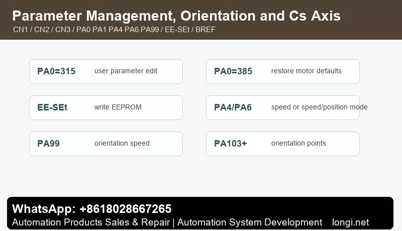
The manual clearly states that PA0=315 is the user parameter modification password. At each power-on, PA0 returns to 315. PA0=385 is used to restore motor default parameters and allows PA1/PA2 editing. PA1 is the motor model code.
EE-SEt writes memory parameters into the EEPROM parameter area. EE-rd reads EEPROM parameters back into memory. EE-bA writes current parameters into the backup area. If a parameter works today but disappears after power cycling, EE-SEt was probably not executed. After final commissioning, execute EE-SEt, then use EE-bA for backup and verify after power cycling.
CN1 Control Signals
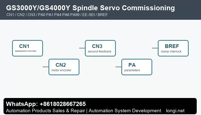
CN1 carries the key interface between CNC and spindle servo: analog speed command, pulse position command, enable, forward/reverse, reset, orientation start, clamp interlock, speed arrival, zero speed, alarm output and position output.
Wire and test in layers. First power and encoder, then enable and alarm output, then speed command and direction, then orientation, speed arrival, zero speed, BREF clamp interlock and position outputs. Do not wire every CN1 signal at once during retrofit; otherwise command faults, feedback faults and PLC interlocks are hard to separate.
The manual appendix gives examples for GSK980TDc and GSK988T. For speed control with orientation, typical settings include PA4=1, PA6=1 for external 0-10 V analog command, PA51 for analog-speed direction reversal, PA99 orientation speed, and PA103/PA105/PA107/PA109 orientation positions. For speed/position Cs-axis control, typical settings include PA4=3, PA5 position-command mode, PA28 position direction and PA90 switching reference.
CN2/CN3 Encoder Feedback
CN2 is motor encoder feedback. CN3 is used on selected GS-N/GS-C configurations for second-position feedback. Speed mode can run with stable speed feedback, but orientation and Cs-axis control require reliable position feedback.
Check encoder type, connector, shield, supply, PA3 position monitor and actual spindle movement. Orientation position should be set from real monitor values, not guessed. With high-resolution magnetic or magnetic-grid encoders, pay attention to high/low position display.
Speed Mode, Orientation and Cs Axis
For external analog speed mode, confirm PA6, analog polarity, 0-10 V range, common terminal, shielding and PA51 direction. Speed arrival must be real; do not short it only to make the CNC continue.
Orientation is used for tool change, fixed spindle position and rigid tapping preparation. PA99 sets orientation speed and PA103-series parameters define orientation positions. If orientation fails, check encoder zero, orientation position, braking mode and mechanical backlash before changing gains.
Cs-axis control treats the spindle as a position axis. Use PA4=3 and configure PA5, PA28 and PA90 according to the CNC system. First test small low-speed angles, then check electronic gear ratio, position arrival and repeatability.
BREF Clamp Interlock and PLC Safety Chain
BREF spindle clamp interlock is important. The spindle should not release the tool before zero speed; it should not start before the tool is clamped; it should not feed before speed arrival or orientation completion. PLC logic should include speed arrival, zero speed, orientation complete, clamp complete, alarm output and emergency stop.
Shorting BREF or speed-arrival signals may keep production moving for a moment, but it increases tool-change and machining risk. Diagnose which interlock condition is missing instead.
Fault Diagnosis
Speed mode does not run: check enable, run command, analog speed command, PA6, PA51, emergency stop, alarm output, input-terminal status and motor wiring.
Wrong direction: check U/V/W, PA51, PA28 and CNC direction signal.
Orientation drift: check CN2/CN3 encoder, shield grounding, coupling, orientation position parameters, braking mode and spindle backlash.
Parameters lost after power-off: execute EE-SEt and then EE-bA after final tuning.
Overvoltage during deceleration: check brake resistor, wiring, heat dissipation, deceleration time and spindle inertia.
Position mode following error: check PA4, PA5, PA28, PA90, electronic gear ratio, encoder feedback and CNC position command.
The practical rule is simple: confirm model and feedback first, use PA0/PA1 to load correct motor parameters, save with EE-SEt, verify CN1 commands and interlocks, rely on CN2/CN3 for orientation and Cs-axis feedback, then diagnose alarms by layer.