GSK DAP03 Spindle Servo Manual Guide: Panel Operation, CN1 CN2 CN3 Wiring, Speed and Position Control, Electronic Gear Ratio, Parameter Write and Alarm Handling
DAP03 Must Be Commissioned as a Closed-Loop Spindle Servo
GSK DAP03, DAY3025 and DAY3100 are spindle servo drive units. Their manual is not only about start and stop. It focuses on spindle motor control, encoder feedback, speed/position mode, CNC interface, parameter management, orientation and alarm handling.
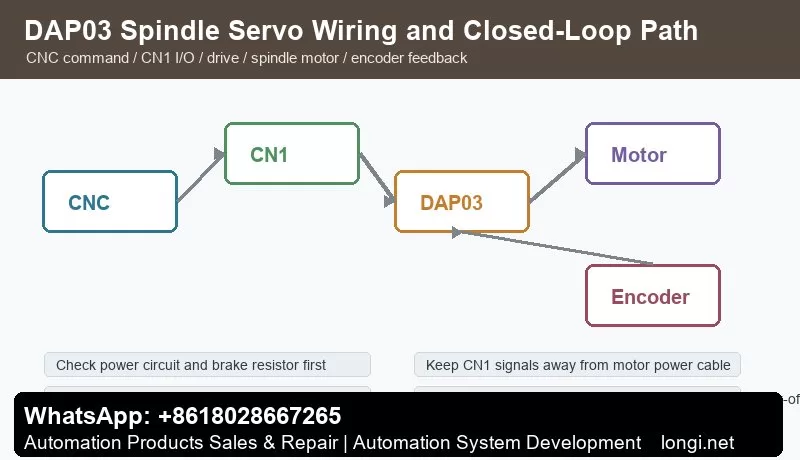
Compared with a normal inverter, a spindle servo must care about encoder feedback, position arrival, speed arrival, electronic gear ratio, spindle orientation, braking stop and CNC machining sequence. If CNC command, CN1 control I/O, DAP03 drive, spindle motor or CN2/CN3 feedback is wrong, the drive may power on but will not run reliably.
This guide follows a field-service route: panel operation, power wiring, CN1 control signals, CN2/CN3 feedback, speed mode, position mode, electronic gear ratio, EEPROM parameter write and alarm diagnosis.
Panel Operation and Parameter Management
The DAP03 panel is used for status display, parameter selection, value editing, manual run, jog run, alarm reset and parameter management. Always read status before changing parameters. The manual separates status monitor, parameter setting and parameter management because temporary changes and permanent storage are different operations.
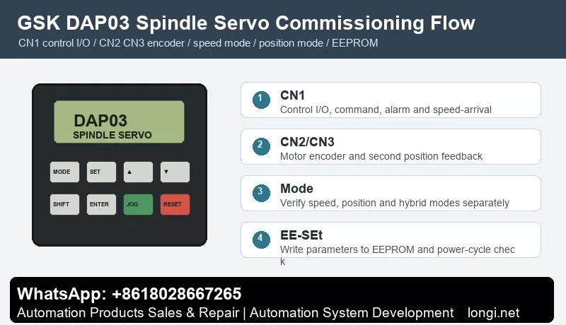
The manual describes EE-SEt as the operation that writes parameters from memory into the EEPROM parameter area. If a user changes a parameter but does not execute parameter write, the value may be lost at the next power-on. In the field, many “it was adjusted yesterday but failed today” cases are caused by missing EEPROM write or missing power-cycle verification.
After initialization, Err-24 may appear if CN3 is not connected to a second position encoder, and Err-5 may appear if the temperature sensor signal on CN2 is not connected. Do not replace the control board first. Check the actual hardware configuration and set the related parameters, such as PA66 and PA73, according to the application, then execute parameter write.
Power Circuit, Brake Resistor and Grounding
Before wiring, verify voltage class, drive capacity, spindle motor model, brake resistor, breaker, contactor and AC reactor. The manual includes peripheral equipment selection for protective devices and reactors, which shows that power-circuit protection is part of the drive system.
Check three points in the main circuit: input and motor output must not be reversed, the brake resistor must match the drive capacity, and PE/shield grounding must be reliable. Spindle acceleration and deceleration can regenerate significant energy. A wrong or undersized brake resistor can cause overvoltage, unstable stop or long stopping distance.
Encoder cable, CN1 control cable and motor power cable should be routed separately. Poor shielding can cause speed fluctuation, orientation failure, position deviation or feedback alarms. On retrofit machines, encoder cables should be separated from contactor coils and motor cables whenever possible.
CN1 Control Signals
The manual lists CN1 pin definition, input signals and output signals. CN1 is the key interface between CNC and spindle drive. Common signals include servo enable, forward/reverse, command input, alarm output, speed arrival, zero speed, position complete, reset and common terminal.
Do not wire every signal at once during commissioning. First connect enable and alarm output, then confirm CNC receives the drive-ready state. Next test forward/reverse or run command. Then connect speed or position command. Finally connect speed arrival, zero speed and orientation-complete feedback. A spindle running on the drive panel does not mean the CNC has received speed-arrival or position-complete feedback.
When used with GSK 218M, GSK 980TDa, GSK 980TD1 or GSK 983M, the appendix wiring examples are useful references. Still, the final wiring should follow the actual machine schematic. Pay attention to common terminals, signal polarity, alarm contact type, command type and reset pulse duration.
CN2 and CN3 Feedback Signals
The manual treats feedback wiring as a separate topic. CN2 and CN3 are related to motor encoder and second position feedback. A spindle servo is a closed-loop system; feedback disconnection, wrong signal type, poor shielding or loose connector can cause unstable speed, failed orientation, position error or alarms.
If the machine has no second position encoder but the function is enabled, Err-24 can occur after initialization. Confirm whether CN3 feedback really exists before changing hardware. If CN2 temperature or encoder-related signals are missing, the drive can also alarm. A good check sequence is: connector, shield, encoder supply, signal waveform and parameter configuration.
Feedback problems often appear only at high speed, during orientation or during rapid acceleration. Do not reduce speed-loop or position-loop gains blindly. Check encoder installation, coupling, cable shielding, grounding and CN2/CN3 connector first.
Speed Mode Commissioning
DAP03 supports speed operation mode. The manual lists analog voltage command and internal digital command. Speed mode is usually used when CNC sends spindle speed. For analog reference, confirm voltage range, direction logic, zero drift, shield and speed scaling. For internal digital command, confirm command value, run source and ramp time.
A practical test sequence is: reduce maximum speed or disconnect risky mechanical load, observe whether the speed command changes on the drive, test low-speed forward and reverse, and then increase speed while observing current, vibration, noise and temperature. If command is zero but the spindle creeps, check analog zero drift, common terminal and zero-speed clamp.
Speed-arrival feedback is important for machining sequence. If CNC sends M03 and the PLC waits for speed arrival, the program may stop if this feedback is missing. If speed-arrival is shorted falsely, feed may begin before the spindle reaches real speed.
Position Mode and Electronic Gear Ratio
The manual includes position mode, speed/position mixed mode and electronic gear ratio for position command. Position mode is used for spindle orientation, rigid tapping, tool-change positioning and angular control.
Before setting electronic gear ratio, confirm four values: CNC command pulses per revolution, encoder feedback pulses per revolution, motor-to-spindle mechanical ratio and whether belt or gear transmission is used. A wrong gear ratio causes orientation offset, inaccurate tapping pitch, repeated position drift or cumulative error.
For the first position-mode test, command only a small pulse distance and observe direction and angle. After direction is correct, verify one revolution, half revolution, orientation position and repeatability. If position arrival is unstable, check electronic gear ratio, position-arrival window, encoder feedback and mechanical backlash before tuning gains.
Brake Stop, Orientation and Interlocks
A spindle servo must not only rotate; it must stop and orient according to process requirements. The function section of the manual covers brake stop, motor direction switching, position arrival, speed arrival, zero speed and orientation. On machining centers and CNC lathes, spindle orientation is often tied to tool change, chuck, tailstock and hydraulic clamping logic.
For brake-stop faults, distinguish electrical braking, resistor braking and mechanical braking. Too short deceleration time, undersized brake resistor or high spindle inertia can cause overvoltage or unstable stop. For orientation failure, check orientation command, position feedback, electronic gear ratio, arrival window and mechanical backlash.
Do not bypass clamping and zero-speed interlocks. The PLC should link speed arrival, zero speed, orientation complete, alarm, clamp confirmation and tool-change conditions into a safe sequence.
Alarm Handling
Err-5 temperature or sensor-related alarm: after initialization or motor replacement, check CN2 temperature signal and related parameters such as PA73 before replacing hardware.
Err-24 second position feedback alarm: if CN3 is not connected but the function is enabled, check configuration such as PA66. If second feedback exists, inspect encoder supply, shield, signal and mechanical mounting.
No rotation in speed mode: check enable, run command, direction, speed command, analog common, E-stop and alarm reset.
Positioning error in position mode: verify electronic gear ratio, feedback pulses, mechanical ratio, direction, arrival window and backlash.
Alarm immediately after run command: check motor power cable, encoder cable, brake resistor, mechanical binding, ramp time and load inertia.
Parameters lost after power cycle: confirm EE-SEt parameter write and verify again after power-off and restart.
Delivery Checklist
- Backup: speed mode, position mode, electronic gear, encoder, brake and alarm parameters.
- Wiring record: CN1, CN2, CN3, power circuit, brake resistor and shield grounding.
- Function test: low-speed forward/reverse, speed arrival, zero speed, orientation, position complete, alarm output and reset.
- Safety interlock: no feed before speed arrival, no unclamp before zero speed, no start before alarm reset.
- Final check: execute parameter write, power cycle and verify critical actions again.
The core of DAP03 commissioning is simple: make feedback reliable first, stabilize speed mode second, make position mode accurate third, then connect speed arrival, zero speed, orientation and PLC interlocks into the machine sequence.