
Introduction
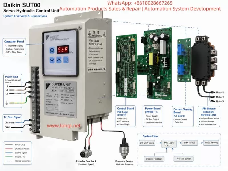
The Daikin SUT00 Super Unit is a servo-hydraulic power system designed primarily for injection molding machines, die-casting machines, and other industrial forming equipment. It is not a conventional fixed-displacement hydraulic power pack, nor is it simply a general-purpose inverter. Instead, it is an integrated closed-loop electro-hydraulic system consisting of an IPM permanent-magnet servo motor, gear pump, pressure sensor, rotary encoder, servo controller, power module, current detection circuit, and hydraulic control components.
The SUT00 system regulates pump output flow by controlling motor speed. At the same time, it uses pressure feedback to perform closed-loop pressure control. Compared with a traditional hydraulic system using a continuously running induction motor, fixed-displacement pump, proportional valve, and relief valve, the SUT00 can adjust motor output according to the actual pressure and flow demand. This significantly reduces energy consumption and oil temperature during standby, pressure-holding, and low-load operation.
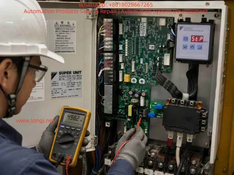
During repair work, the controller may require replacement of the control board, power-supply board, current detection board, driver board, or IPM power module. After these components are replaced, technicians often encounter a panel indication reading “StP.”
Because “StP” is not a conventional numerical alarm code, it is often misinterpreted as a controller initialization failure, software mismatch, missing program, incompatible power module, or defective replacement board. In many cases, however, “StP” simply means that the controller is in the Stop state. The controller has completed its basic power-up process but has not received a valid pump start command.
Nevertheless, after board replacement, “StP” should not be cleared by blindly shorting terminals or forcing the pump to start. The technician must verify the start/stop digital input, parameter settings, board compatibility, pump-controller matching parameters, pressure and flow commands, Ready status, encoder feedback, pressure sensor feedback, and thermistor circuit before attempting operation.
This article explains the meaning of “StP,” the start logic of the Daikin SUT00, the parameters that must be checked after controller replacement, the correct troubleshooting sequence, and the precautions required during the first trial run.
1. Basic Construction and Operating Principle of the Daikin SUT00 System
The Daikin SUT00 series mainly consists of the following components:
- Three-phase servo controller
- IPM permanent-magnet synchronous motor
- Gear-type hydraulic pump
- Motor rotary encoder
- Hydraulic pressure sensor
- Motor thermistor
- Motor cooling fan
- Main control board
- Driver and power-supply board
- IPM intelligent power module
- Current detection board
- External pressure, flow, and start/stop command interfaces
The machine controller normally sends two analog signals to the SUT00:
- Pi: pressure command
- Qi: flow-rate command
The SUT00 also sends monitor signals back to the machine controller:
- Po: pressure monitor output
- Qo: flow-rate monitor output
During operation, the controller calculates the target motor speed according to the Qi flow command. The encoder detects the actual motor speed, and the controller regulates the U, V, and W phase currents through the IPM power module so that the motor reaches the commanded speed.
As the hydraulic pressure rises and approaches the Pi pressure command, the controller transitions from flow control to pressure-limiting or pressure closed-loop control. It then reduces motor speed automatically to prevent the actual pressure from exceeding the target pressure.
Therefore, the SUT00 does not merely output a fixed three-phase frequency. It simultaneously evaluates:
- Pressure command
- Flow command
- Pressure feedback
- Motor speed feedback
- Motor current
- Motor temperature
- Controller temperature
- Digital start/stop input
- External interlock conditions
The SUT00 controller uses a three-phase 380–440 VAC power supply. The motor cooling fan usually requires an additional single-phase 215–245 VAC power supply. For the SUT00S13018 model, the rated maximum flow is 130 L/min and the maximum operating pressure is 17.6 MPa.
2. What Does “StP” Actually Mean?
“StP” is generally an abbreviation of Stop. It indicates that the pump motor is currently in the stopped state.
This is fundamentally different from an alarm.
A real fault alarm normally appears as a specific alarm number or code. It may also cause the Ready output to turn OFF and prohibit motor operation. By contrast, “StP” mainly indicates that the controller is not currently executing a pump run command.
When the operation panel displays “StP” steadily, it normally suggests that:
- The control-board CPU has started;
- Communication between the panel and the main control board is functioning;
- At least part of the low-voltage control power supply is operating;
- No immediate severe hardware alarm has been detected at power-up;
- The motor has not yet been enabled to run.
Therefore, “StP” by itself is not direct evidence of a failed IPM module or defective control board.
However, “StP” also does not prove that the controller is fully functional. Since the controller has not yet driven the motor, some faults may only appear after a valid start command is received, including:
- Encoder fault
- Motor phase loss
- IPM driver fault
- Current detection abnormality
- Motor overcurrent
- DC-bus undervoltage
- IPM protection trip
- Speed deviation
- Abnormal pressure rise
- Motor thermistor fault
For this reason, “StP” should be interpreted as the controller is stopped and waiting, not as confirmation that the repair has been completed successfully.
3. The SUT00 Is Not Normally Started from the Panel
The operation-panel keys are mainly used for:
- Switching monitor modes
- Viewing operating data
- Entering parameter-setting mode
- Viewing alarm history
- Modifying permitted parameters
Unlike a general-purpose inverter, the panel does not normally provide a direct RUN key for starting the hydraulic pump. The pump motor is primarily started and stopped through digital input DI1.
Parameter P00, identified as the DI_A start/stop signal switching parameter, determines the DI1 logic:
| P00 setting | DI1 OFF | DI1 ON |
|---|---|---|
| 0 | Pump stop | Pump run |
| 1 | Pump run | Pump stop |
When P00 is set to 0, DI1 ON means Run. When P00 is set to 1, the logic is reversed and DI1 OFF means Run.
This is one of the most common reasons for an StP indication after a control-board replacement.
For example, assume the original controller used:
P00 = 0
The machine PLC sends 24 V to DI1 whenever the hydraulic pump is required to run.
If the replacement control board contains:
P00 = 1
the same 24 V input is interpreted as a stop command instead of a run command.
From the PLC side, the pump-start output appears to be active. From the SUT00 controller side, however, the stop condition remains valid. The panel therefore continues to display “StP.”
For this reason, it is not sufficient to verify that 24 V exists at the DI1 terminal. The P00 input logic must also be checked.
4. Main Reasons for an “StP” Display After Board Replacement
4.1 No DI1 Start Signal Is Reaching the Controller
An injection molding machine normally does not start the hydraulic pump immediately after power-up. Several interlock conditions may have to be satisfied first, such as:
- Emergency stop reset
- Safety door closed
- Main PLC running normally
- Oil level switch normal
- Oil temperature normal
- Motor thermal protection normal
- Servo controller Ready signal present
- No hydraulic-system alarm
- Machine in an operating mode that permits pump start
- Pump-start pushbutton or command activated
If any required interlock remains unsatisfied, the PLC may not energize DI1.
Common field problems include:
- DI1 wire omitted during reassembly
- Connector not fully inserted
- Ribbon cable misaligned
- DICOM not connected
- External 24 VDC supply missing
- Wrong DI1 polarity
- Failed PLC output relay
- Different terminal definition between original and replacement board
- Loose terminal screw
- Bent connector pin
Therefore, when “StP” appears after board replacement, the first task is to determine whether the controller is actually receiving the DI1 signal.
4.2 P00 Does Not Match the Original Controller
A replacement control board may still contain factory-default parameters, or it may have been removed from another machine.
Even if the board number appears identical, its stored parameters may not be suitable for the current machine. If P00 differs from the original setting, the start logic will be reversed directly.
The technician should enter parameter-setting mode, read the current P00 value, and compare it with:
- The original controller parameter record
- The machine electrical schematic
- PLC output logic
- Actual DI1 voltage changes
- Machine commissioning records
If no original documentation is available, the DI1 monitor status and machine start behavior can be used for diagnosis. However, parameters should not be changed casually and followed immediately by high-pressure operation.
4.3 Original Parameters Have Not Been Restored
A Daikin SUT00 controller is not fully interchangeable merely because the replacement board has the same appearance or board number.
During factory commissioning, the controller is configured according to:
- Actual pump displacement
- Pressure sensor characteristics
- Analog command range
- Hydraulic response
- Machine motion requirements
- Motor and controller calibration
If the original parameters are not restored after controller replacement, the system may run but exhibit serious performance problems, including:
- Insufficient maximum flow
- Failure to build pressure at low flow
- Incorrect pressure indication
- Actual pressure higher than commanded
- Abnormal motor speed
- Unstable pressure holding
- Slow response
- Pressure shock
- Speed alarm
- Incorrect flow scaling
- Machine motion speed different from the original condition
The manual specifies that original controller parameters should be restored after controller replacement. In particular, H15, H30, and P07 are closely related to the pump, pressure sensor, and controller matching calibration.
4.4 The Ready Condition Has Not Been Established
After power-up, the controller must complete internal initialization, including:
- Control power stabilization
- CPU program execution
- Memory reading
- Initial sensor checks
- DC-bus status detection
- Protection-circuit self-check
- I/O initialization
Only when the controller reaches the permissible operating state does the Ready output turn ON.
If Ready is not established, the external PLC may refuse to send the pump-start command. This creates a sequence such as:
- SUT00 controller is not Ready;
- PLC does not output pump start;
- Controller remains in StP;
- Machine controller waits for the hydraulic-unit Ready signal.
In this case, the technician must not focus only on DI1. The DO1 Ready output, alarm history, and internal monitor values must also be checked.
4.5 Compatibility Problems Between the Control Board, Driver Board, and IPM Module
The power module shown in the repair photographs is a Mitsubishi Electric PM100RL1A120 series IPM module. Such modules typically integrate power semiconductor devices, gate-drive protection, and fault-feedback functions.
When replacing an IPM module, the following points must be confirmed:
- Exact complete model number
- Voltage rating
- Current rating
- Pin assignment
- Module revision compatibility
- Correct mounting screw torque
- Good thermal contact with the heat sink
- Uniform thermal compound thickness
- Correct insulation-sheet condition
- Driver connector installed in the correct orientation
- No shifted control pins
- Correct DC positive and negative bus connections
- Correct U, V, and W output connections
If the IPM module or driver board is incompatible, the controller may remain normal while stopped but trip immediately when a start command is applied.
Therefore, static checks must be completed before DI1 is enabled.
5. Parameters That Must Be Checked After Controller Replacement
5.1 P00: Start/Stop Input Logic
P00 determines whether DI1 ON or DI1 OFF represents Run.
This is the first-priority parameter when the panel remains in “StP.”
5.2 P05: VMAX Analog Command Full-Scale Voltage
The SUT00 normally uses 0–10 V pressure and flow commands, but the actual full-scale input voltage is parameterized.
An incorrect VMAX setting may cause:
- A 10 V command to produce less than full output
- A small voltage to produce excessive pressure or flow
- Pressure not proportional to the machine setting
- Severe flow-scaling error
5.3 P06: PMAX Maximum Pressure Scaling
P06 defines the maximum pressure corresponding to the full-scale pressure command.
Although the SUT00S13018 has a rated maximum operating pressure of 17.6 MPa, the actual machine may be configured for a lower maximum pressure due to:
- Hydraulic circuit limitations
- Mold-protection requirements
- Machine design
- Process requirements
The system should never be tested immediately at 17.6 MPa simply because that is the model’s maximum rating.
5.4 P07: QMAX Maximum Flow Scaling
P07 defines the maximum flow corresponding to the full-scale flow command.
The SUT00S13018 is rated for up to 130 L/min, but the pump and controller are factory-matched and calibrated. The P07 value stored in a spare controller may not be correct for the installed pump assembly.
The manual requires the original P07 value to be written into the replacement controller.
5.5 H15: Q_EV Flow Correction Coefficient
H15 compensates for actual pump-output characteristics, particularly during low-flow operation and pressure build-up.
An incorrect H15 value may cause:
- Difficulty building pressure at low flow
- Unstable pressure holding
- Motor rotation without sufficient pressure rise
- Low-flow pressure-rise alarm
- Difference between calculated and actual pump output
The manual indicates that H15 may require adjustment if abnormal pressure rise occurs at a low flow setting after pump replacement or commissioning.
5.6 H30: PS_G Pressure Sensor Gain
H30 calibrates the pressure sensor feedback.
If H30 is incorrect, there may be a difference among:
- Actual hydraulic pressure
- SUT00 panel pressure indication
- Machine HMI pressure indication
- Po pressure monitor output
If the pressure sensor gain is too low, the controller may believe pressure is insufficient and continue increasing motor torque, causing excessive actual pressure.
If the gain is too high, the controller may reduce speed too early and fail to reach the required pressure.
After replacing the pressure sensor or controller, H30 must be restored correctly or recalibrated. The manual recommends comparing the controller reading with an accurate pressure gauge in pressure-control operation.
5.7 H21 to H28 Must Not Be Copied Directly
The manual specifically states that H21 to H28 are controller-specific calibration values.
Therefore, after replacing the controller:
- Machine operating parameters may be restored;
- H15, H30, and P07 may be transferred as required for pump matching;
- H21 to H28 must not be copied from the old controller into the replacement controller.
Doing so may corrupt the replacement controller’s own current-detection, hardware-calibration, or drive-compensation data.
6. Standard Troubleshooting Procedure When “StP” Is Displayed
Step 1: Confirm the Unit Model and Replacement Component Information
Record the complete nameplate and board information, including:
- SUT00S13018-10YA-N0218
- Controller manufacturing number
- Pump and motor manufacturing number
- Control-board number
- Power-board number
- IPM module model
- Current detection board number
- Software revision
- Hardware revision
The Daikin manual states that the motor-pump assembly and controller are tested as a matched pair before shipment. In principle, the controller and pump assembly should have the same manufacturing number.
When using replacement boards, at minimum confirm that the product series, power rating, software version, motor type, and feedback method are compatible.
Step 2: Perform Static Checks with Power Disconnected
Disconnect the three-phase power supply and wait at least five minutes for the DC-bus capacitors to discharge.
Then check:
- No short circuit between the DC-bus terminals P1 and P2;
- U, V, and W phase resistance characteristics are approximately symmetrical;
- Diode-test characteristics from U, V, and W to the positive and negative DC bus are symmetrical;
- U, V, and W are insulated from ground;
- Motor winding resistances are balanced;
- Motor insulation to ground is acceptable;
- IPM module mounting surface is flat;
- Mounting screws are secure;
- Current detection board is installed in the correct direction;
- All connectors are fully inserted;
- Ribbon-cable contacts are clean;
- No bent pins, cracked solder joints, or burn marks are present.
A standard multimeter can only provide a preliminary assessment. It cannot prove that the IPM module is dynamically healthy under load.
Step 3: Power Up Without Immediately Starting the Pump
During the first power-up after repair, do not immediately allow the PLC to issue a run command.
Observe:
- Whether the panel powers up normally;
- Whether “StP” is displayed;
- Whether any other alarm appears;
- Whether the control board produces abnormal sound;
- Whether the power-supply board heats abnormally;
- Whether the IPM module heats rapidly;
- Whether the DC-bus voltage is normal;
- Whether the Ready output is established;
- Whether the cooling fans operate as designed.
If a serious alarm appears immediately, resolve that alarm before any attempt to start the motor.
Step 4: Check the Actual DI1 Status
Measure the voltage between DI1 and DICOM with a multimeter.
Record the voltage under both conditions:
- Machine stopped;
- Pump-start command activated.
If the voltage does not change, the problem is most likely in the external control circuit.
Check:
- 24 VDC power supply
- PLC output
- Interposing relay
- Terminal wiring
- Emergency-stop circuit
- Safety-door circuit
- Ready interlock
- DICOM connection
If the voltage changes but the panel still displays “StP,” enter monitor mode and verify whether the controller internally detects the DI1 change.
Step 5: Read P00
Confirm that P00 matches the external DI1 logic.
For example:
- If DI1 changes from 0 V to 24 V when the machine requests pump operation, P00 is commonly set to 0;
- If DI1 is energized during stop and released during Run, P00 may be set to 1.
The correct setting must be determined from the original circuit and actual input status, not from assumption alone.
Step 6: Check Pressure and Flow Commands
Even if DI1 is in the Run state, the system may remain in a low-output standby condition if both Pi and Qi are zero or near zero.
The manual describes a standby condition when the pressure and flow commands are low. Parameter P15 BIAS defines the standby pressure behavior.
The following monitor values should be checked:
- Pi pressure command voltage
- Qi flow command voltage
- Pressure feedback
- Flow feedback
- Actual motor speed
- Digital input status
If the machine has issued a motion command but Pi and Qi remain at 0 V, inspect the analog signal wiring and analog common connection.
Step 7: Restore the Original Controller Parameters
The best method is to read and record all parameters from the original controller before removal.
If the original controller is completely damaged, search for:
- Machine manufacturer parameter sheet
- Injection molding machine commissioning records
- Another identical operating machine
- Previous repair records
- Parameter photographs
- PLC or HMI process-setting records
The parameters should be divided into three categories.
Machine Parameters That May Be Restored
These include P00, P05, P06, P07, P15, and pressure- and flow-response parameters.
Pump-Matching Parameters That Must Be Restored
These include H15, H30, and P07.
Controller-Specific Parameters That Must Not Be Copied
These include H21 to H28.
7. Low-Risk Procedure for the First Trial Run
Only after the previous checks are completed should the unit be started.
7.1 Place the Hydraulic Circuit in an Unloaded Condition
Avoid immediately performing:
- High-pressure clamping
- Injection
- Ejector operation
- High-pressure mold locking
- Driving a cylinder against its mechanical stop
- Long pressure-holding operation
Where possible, select an unloaded return path or a low-load machine movement so that the pump will not immediately build high pressure.
7.2 Use Low Pressure and Flow Commands
For an initial trial, use low command values, such as:
- Pressure command: approximately 0.5–1.0 V
- Flow command: approximately 0.3–0.5 V
The exact values must be selected according to the machine’s actual command scaling.
Do not apply 10 V pressure and 10 V flow commands during the first test. If H30, P06, P07, or H15 is incorrect, the result may be uncontrolled pressure or motor speed.
7.3 Perform a Short Jog Test
The first run may be limited to approximately one or two seconds.
Observe:
- Whether the motor rotates smoothly;
- Whether there is severe vibration;
- Whether the pump produces a sharp cavitation sound;
- Whether motor direction is correct;
- Whether pressure rises abnormally quickly;
- Whether the three-phase currents are balanced;
- Whether an alarm appears immediately;
- Whether the IPM module heats abnormally.
Stop immediately if any abnormal condition is detected.
7.4 Confirm Pump Rotation Direction and Oil Suction
If the U, V, and W phase sequence or the encoder matching relationship is incorrect, the motor may not operate correctly in closed loop.
Reverse pump rotation may cause:
- Failure to draw oil
- No pressure rise
- Abnormal pump noise
- Pump damage
- Incorrect encoder speed direction
- Speed deviation or overcurrent alarm
Motor rotation alone does not confirm correct pump direction.
7.5 Verify Pressure Feedback Accuracy
Use a mechanical pressure gauge or a calibrated electronic pressure gauge to compare:
- Actual hydraulic pressure
- SUT00 panel pressure
- Machine HMI pressure
- Po pressure monitor output
If the difference is significant, do not continue increasing pressure. Check:
- Pressure sensor
- Pressure sensor power supply
- Signal wiring
- H30 setting
- Analog monitor scaling
- Pressure sensor installation point
8. Common Incorrect Repair Actions and Their Risks
8.1 Shorting DI1 Immediately After Seeing “StP”
If P00 is configured for reverse logic, shorting DI1 may not start the pump. More importantly, forcing DI1 can bypass machine safety logic and cause unexpected movement.
The correct method is to read the DI1 state and confirm P00 first.
8.2 Failing to Restore Parameters After Board Replacement
The controller may appear to run, but the hydraulic performance can differ significantly from the original machine.
8.3 Copying All H Parameters from the Old Controller
H21 to H28 are specific to the replacement controller and must not be overwritten with values from the old board.
8.4 Applying Maximum Pressure and Flow During the First Run
This amplifies any error in pressure feedback, flow scaling, or current detection and may damage the replacement IPM module again.
8.5 Ignoring the Encoder Circuit
The SUT00 uses encoder feedback for speed closed-loop control. A loose connector, missing encoder supply, abnormal A/B phase signals, or incorrect direction can cause serious speed-control faults.
8.6 Ignoring the Motor Thermistor and Cooling Fans
The motor thermistor, controller fan, and motor cooling fan are important protection components. A missing fan supply may not cause an immediate power-up fault but can result in overheating during operation.
8.7 Applying a Megohmmeter Directly to Electronic Circuits
A megohmmeter can damage:
- Encoder
- Pressure sensor
- Control board
- IPM control terminals
- Analog input circuits
Insulation testing should be performed only on the motor windings and power cables after electronic components have been properly disconnected.
9. Criteria for Confirming a Successful Repair
A repair should not be considered complete merely because the panel exits “StP.”
A satisfactory result should include all of the following:
- No abnormal alarm at power-up;
- Ready output operates correctly;
- DI1 status corresponds to the external start command;
- P00 logic is correct;
- “StP” disappears when valid run conditions are satisfied;
- Motor runs smoothly at low speed;
- Encoder feedback is stable;
- Three-phase current is reasonably balanced;
- Pressure command agrees with actual pressure;
- Flow command produces the expected speed response;
- No abnormal noise or vibration;
- IPM module temperature rise is normal;
- Motor and controller cooling fans operate correctly;
- Low-pressure, low-flow, and pressure-holding operation are stable;
- High-pressure and high-flow tests are introduced gradually without alarms;
- Machine motion speed returns to the original performance;
- Final parameter values are recorded and backed up.
Only after these conditions are met can the repaired SUT00 unit be considered technically reliable.
10. Conclusion
When a Daikin SUT00 servo-hydraulic control unit displays “StP” after replacement of the control board, power-supply board, current detection board, or IPM module, the indication normally means that the controller is in the Stop state. It does not automatically indicate a hardware fault.
The most common causes are:
- No DI1 start command
- Incorrect external 24 V or DICOM wiring
- P00 start logic different from the original controller
- Ready condition not established
- PLC safety interlock not satisfied
- Original controller parameters not yet restored
The correct solution is not to short terminals blindly or continue replacing power modules. The technician should follow a structured sequence:
static inspection → power-up initialization → Ready verification → DI1 monitoring → P00 verification → parameter restoration → low-risk jog test → pressure and flow calibration
Particular attention must be paid to H15, H30, and P07. These parameters are associated with flow correction, pressure sensor gain, and maximum flow scaling. At the same time, H21 to H28 are controller-specific calibration values and should not be copied from the old controller into the replacement controller.
The Daikin SUT00 is a multi-loop servo-hydraulic system integrating pressure, flow, speed, and current control. It should not be diagnosed using only the logic of a standard contactor-driven motor or general-purpose inverter. Reliable recovery requires correct power hardware, valid sensor feedback, correct digital start logic, proper analog command scaling, and accurate control parameters. Only when all of these elements are verified can the original pressure accuracy, motion speed, operating stability, and long-term reliability of the machine be restored.