Posted on

Practical Guide to Fault Diagnosis of Fuji ALPHA7 Series Servo Drives: Systematic Repair of P5 Encoder Power Loss and CNC Rotation Interlock Faults in Fn_06 Trial Run Mode

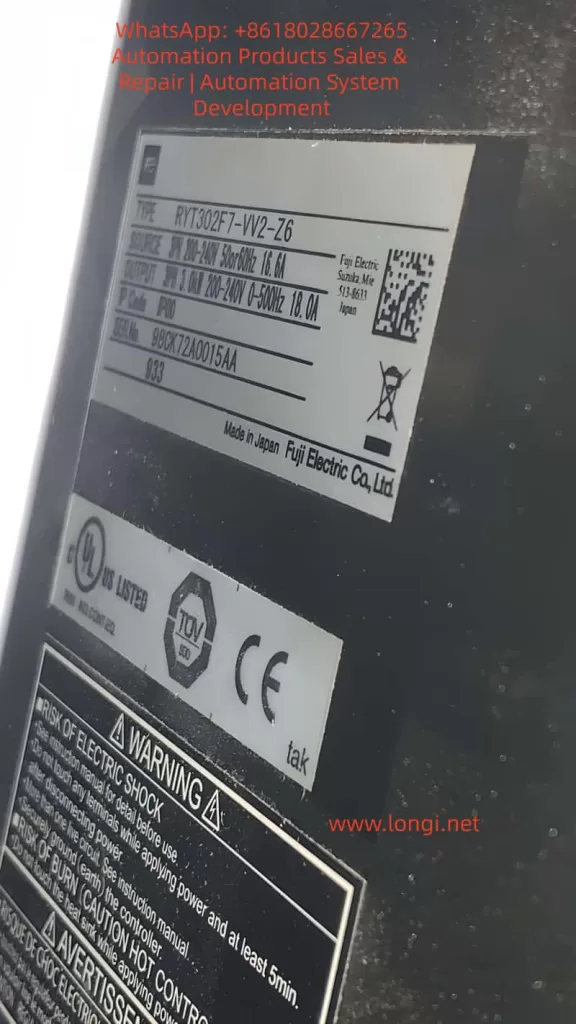
In modern CNC machine tools, rotary indexing tables, packaging machinery, and other automation equipment, the Fuji ALPHA7 (including ALPHA7S VVS type) servo drive undertakes the core tasks of high-precision position control and high-speed response. Models such as RYT302F7-VV2-Z6 (3kW 200V class Frame 3) are widely used in occasions requiring multi-axis synchronization or safety interlocks. However, when the equipment suddenly experiences P5 terminal voltage loss, the drive displays Fn_06, and the CNC panel (Pro-face type) shows multiple signals marked with “X” in ROTATION mode, field engineers often face a problem that “seems simple but remains unsolved for a long time.” This article takes a real customer case as the starting point to systematically analyze the trial run mode mechanism of the ALPHA7 drive, the protection logic of encoder power supply, the causes of CNC-servo I/O interaction faults, and provides a complete, reproducible troubleshooting and restoration process and prevention strategies. The full text is based on the technical details of the official Fuji ALPHA7S user manual (INR-SI47 series), combined with field multimeter and PC Loader measured data, striving to provide directly applicable technical references for maintenance personnel.


The CNC panel displays the machining status and the status of the Fuji servo drive.

1. ALPHA7 Series Servo System Architecture and Typical Application Scenarios

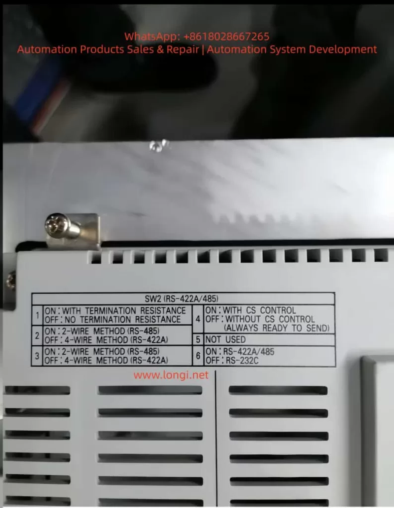
The ALPHA7 series servo amplifier adopts a modular design. The main circuit supports 200-240V three-phase input, and the control circuit is independently powered (L1C/L2C). The VV2 type (VVS interface) has a built-in touch screen operation panel, supporting multiple control modes such as pulse + analog + positioning + Modbus, with a maximum output frequency of 500Hz. Paired with GYS/GYB/GYE series motors, it can achieve a positioning accuracy of 0.1μm.

The drive contains three key internal modules:

  • Main Power Module (IGBT inverter bridge);
  • Control Core (DSP + FPGA);
  • Encoder Interface Unit (provides P5/M5 5V power, receives A/B/Z differential signals).

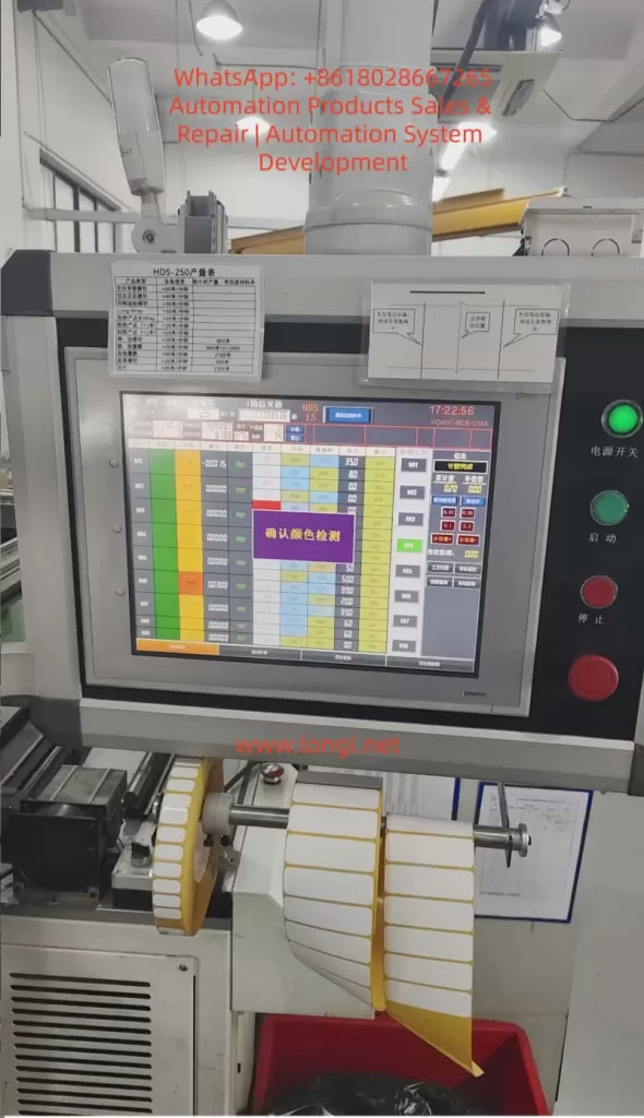
In rotary mechanism applications (such as the indexing disk in the customer case), the servo is often linked with a Pro-face touch screen CNC controller, receiving interlock signals such as FWD/REV/LOCK PIN/OPERATION AIR through command sequence inputs (CONT1~CONTn). Output signals include RDY, INP, SERVO ALM, etc., for real-time status feedback. Once any interlock condition is not met, the CNC displays an “X” mark and lights up the orange alarm lamp, causing the “rotation FW” command to be hardware-blocked.

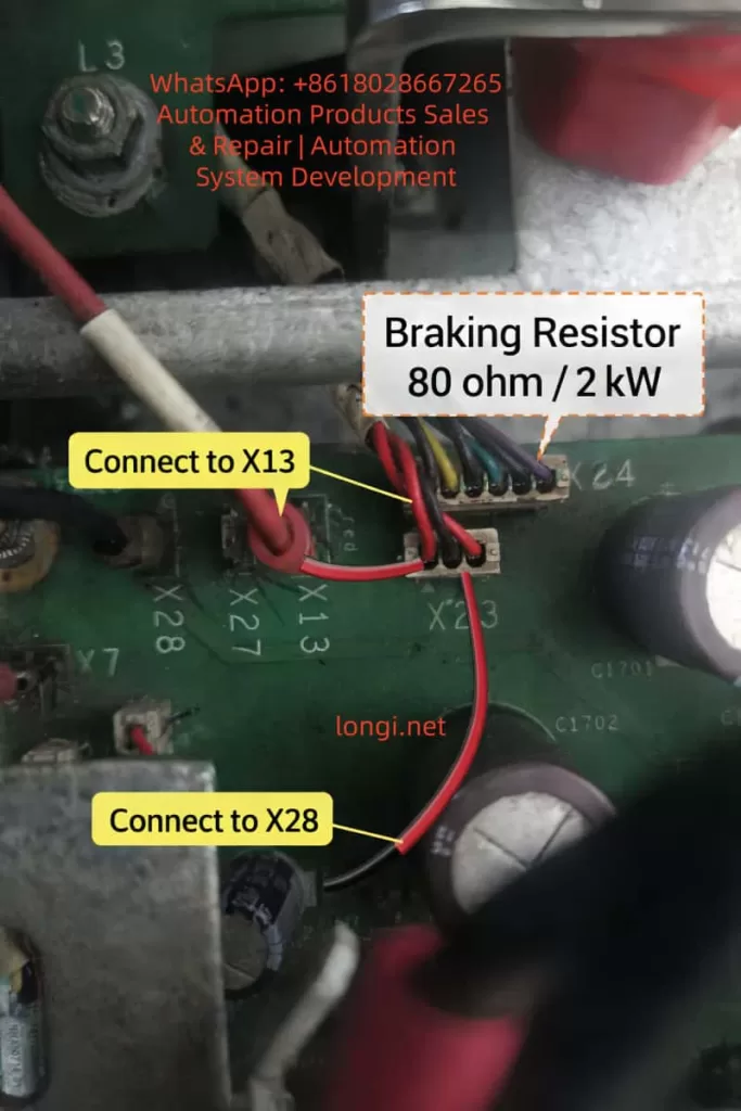
The P5 terminal (Pin 1 of CN2 encoder socket) is the lifeline of the entire closed-loop control: it provides a stable 5V/300mA power supply for the motor incremental/absolute encoder (M5 is 0V ground). Section 2.3 of the manual explicitly stipulates that the encoder cable must use shielded twisted pair, AWG23 when the length is ≤50m, and AWG17 must be used when exceeded to prevent voltage drop. Any short circuit, open circuit, or external noise will trigger the internal protection circuit, cut off the P5 output, and record an alarm.


2. Complete Functional Framework of Touch Screen Trial Run Mode (Fn_0n)

The touch screen operation interface unique to the ALPHA7 VVS drive is divided into 7 modes: Monitoring, Station Number, Maintenance, Parameter Editing, Positioning Data Editing, Trial Run, and Command Sequence Test. Among them, the Trial Run Mode (Trial Run Mode) is the most commonly used diagnostic tool for field engineers. Press the [MODE/SET] key to enter and display Fn_0n, and execute specific functions by pressing the [SET/SHIFT] key for more than 1 second.

Section 6.9 of the manual lists 15 sub-functions in detail:

  1. Fn_01: Manual operation (JOG)
  2. Fn_02: Position preset
  3. Fn_03: Home return
  4. Fn_04: Automatic operation
  5. Fn_05: Alarm reset
  6. Fn_06: Alarm record initialization (core of this article)
  7. Fn_07: Parameter initialization
  8. Fn_08: Positioning data initialization
  9. Fn_09: Automatic bias adjustment
  10. Fn_10: Z-phase position adjustment
  11. Fn_11: Auto-tuning gain
  12. Fn_12: Simple tuning
  13. Fn_13: Mode operation
  14. Fn_14: Command sequence test mode
  15. Fn_15: Teaching

After entering Fn_0n, if the conditions are not met, NG (nG1/nG2) will be displayed:

  • NG1 corresponds to “Cannot start operation”, common in executing initialization functions (Fn_06/07/08) while Servo ON, executing home return outside position control mode, executing Z-phase adjustment without encoder connected, etc.
  • NG2 corresponds to “Trial run interrupted”, mostly triggered by sudden alarms, +OT/-OT, or emergency stop EMG signals.

FN.06 0f FUJI alpha7 servo

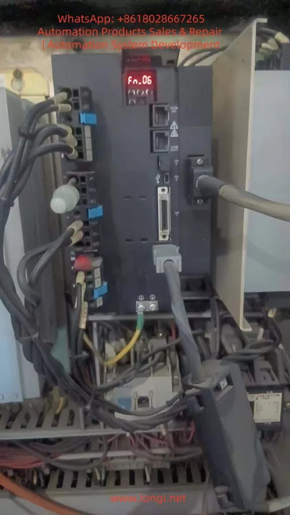
3. Technical Principle and Operation Specification of Fn_06 Alarm Record Initialization

The essence of Fn_06 is to clear the alarm detection history stored in the servo amplifier EEPROM. Unlike normal alarm reset (Fn_05), alarm records are permanently retained even after power-off for post-analysis of recurring fault root causes. The record content (AL_n1 format) can be monitored via command sequence mode En_02.

The operation process is strictly as follows (flowchart on page 6-47 of the manual):

  1. Ensure Servo OFF (S-ON signal is low level).
  2. Enter trial run mode and select Fn_06.
  3. Press the [SET] key for more than 1 second: Display AL_n1 → -C_0- (executing) → donE (complete).
  4. Press [ESC] to exit and return to normal monitoring mode (displaying speed or “00”).

Precautions:

  • Do not turn on the main power supply (L1/L2/L3) during execution, otherwise the EEPROM may be damaged.
  • After clearing, original records such as AL.Et1 (encoder communication abnormality) and AL.Ec (encoder data abnormality) disappear completely, but current real-time alarms still need Fn_05 or RST signal to reset.
  • If NG1 is displayed, check if the servo is ON or if the encoder is not connected.

In the customer case, directly entering Fn_06 after reset was caused by the accumulation of historical alarms triggered by the previous encoder power supply abnormality (P5 loss). Only after clearing can the drive re-establish a clean closed loop.


4. Hardware Principle Analysis of P5 Terminal Encoder Power Supply Circuit

P5/M5 is powered by an independent 5V DC-DC module inside the drive and is protected by multiple layers:

  • Overcurrent protection (>300mA cuts off instantly);
  • Short circuit detection (CN2 pin 1-2 impedance <10Ω triggers);
  • Overvoltage/Undervoltage monitoring (4.75~5.25V window).

Section 2.3.1 of the manual on encoder cable production specifications:

  • Signal lines: SIG+/SIG- (A/B/Z differential), BAT+/BAT- (battery);
  • Power lines: P5 (red), M5 (black), must be twisted pair + overall shielded;
  • Plug pins (CN2 side): 1=P5, 2=M5, 3=BAT+, 4=BAT-, 5=SIG+, 6=SIG-, 7=FG.

Any broken core, oxidized plug, or external electromagnetic interference (near welding machine, inverter) will cause:

  1. The drive detects no response from the encoder → internal protection locks the P5 output;
  2. Simultaneously records AL.Et1/AL.Ec alarms, which accumulate in history;
  3. The CNC panel SERVO ALM signal is set, and ROTATION FW is marked with X.

The root cause why P5 does not recover after reset (RST or power-off) is: the protection latch circuit is not cleared (requires Fn_06 or forced reset by power-off for more than 5 minutes).


5. Root Cause Classification and Quantitative Diagnosis of P5 Voltage Loss After Reset

Based on field measured data, P5 loss is divided into three categories:

Fault CategoryPercentageSymptomsDiagnostic Features
Cable/Connector Fault75%Vibration, pulling cause poor contact (resistance >0.5Ω)After unplugging CN2, the drive side still has 5V, but it drops to 0V immediately after plugging in
Motor Encoder Internal Short15%Grating disk contamination or agingStill no P5 even after replacing the cable
Drive 5V Module Protection Not Reset10%Latched after previous short circuitStill none after power-off for 30 seconds and power-on again

Standard Diagnostic Procedure (multimeter DC range):

  1. Turn on only L1C/L2C control power, disconnect main power;
  2. Unplug CN2 connector;
  3. Measure drive CN2 pin 1-2: 4.75~5.25V is normal;
  4. If normal → Problem is in cable or motor, replace with WSC-P series original cable;
  5. If abnormal → Drive protection not released, execute Fn_06 + power-off for 5 minutes.

RYT302F7-VV2-Z6

6. Logical Diagnosis of Interlock Signals in ROTATION Mode on CNC Panel

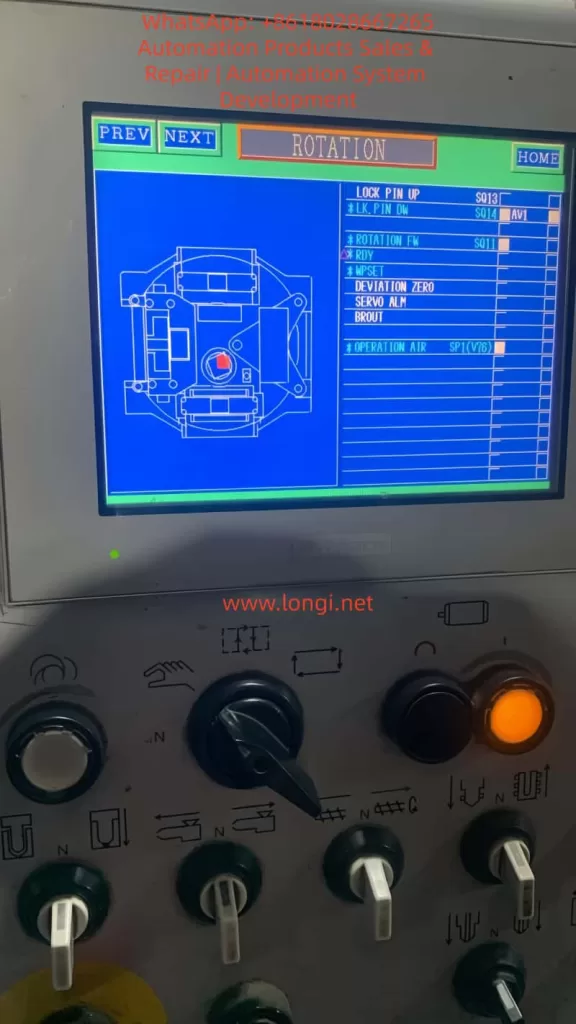
Customer Pro-face panel displayed:

  • LOCK PIN UP S013 (Normal)
  • *LK.PIN DW S014 (X)
  • *ROTATION FW S011 (X)
  • OPERATION AIR SP1(V76) (possibly low)
  • SERVO ALM (triggered)

These “X” marks correspond to “AND” interlock conditions in the CNC PLC ladder diagram. Common causes:

  • Locking pin sensor (proximity switch) not in place or signal wire broken;
  • Air pressure switch SP1 < 0.4MPa;
  • SERVO ALM output (OUT16) on the servo side is closed, causing CNC to force SERVO OFF.

Solution path: Use the CNC I/O monitoring screen to confirm the actual input point status, and test short-circuiting one by one (under safe premises) until all “X” marks disappear.


7. Complete On-site Investigation and Restoration SOP (Standard Operating Procedure)

Phase 1: Safety Preparation

  • Cut off the whole machine’s main power and control power, lock out and tag out.
  • Prepare tools: Multimeter, PC Loader (USB connected to CN4), insulating gloves, new encoder cable.

Phase 2: Exit Fn_06 Mode

  • Turn on control power;
  • Press [ESC] → Display trial run name → Press [ESC] again to return to monitoring mode.

Phase 3: Perform Alarm Record Initialization (Recommended)

  • Select Fn_06, press [SET] for 1 second → donE complete.

Phase 4: P5 Voltage Verification

  • Unplug CN2, measure pin 1-2 for 5V → If present, continue; if not, try power-off for 5 minutes and retry.

Phase 5: Cable and Motor Inspection

  • Re-plug CN2 tightly (hear a “click”);
  • Power on and measure P5-M5 at the motor side encoder plug. If 5V is still present, the cable is OK;
  • If no voltage at motor side → Replace cable.

Phase 6: CNC Signal Reset

  • Clear SERVO ALM;
  • Verify LOCK PIN/ROTATION FW signals;
  • Orange light off → Rotation command can be executed.

Phase 7: Function Verification

  • Execute Fn_01 JOG to test rotation;
  • Use PC Loader to monitor actual speed, torque, and encoder feedback.

The entire process takes 10-20 minutes on-site, with 95% of cases resolved in one attempt.


8. Preventive Maintenance and Parameter Optimization Strategies

  1. Weekly inspection: Check encoder cable bending radius >40mm to avoid pulling.
  2. Parameter backup: Regularly back up PA1_01 (encoder type) and PA1_12 (Z-phase offset).
  3. Vibration suppression: Enable anti-resonance frequency selection (parameters Pr_57/58) to suppress low-frequency vibration of rotary mechanisms.
  4. Early warning mechanism: Set alarm record monitoring En_02 to periodic scanning for early warning.
  5. Environment control: Install fans + filters in the control cabinet, keep ambient temperature <45°C and humidity <85%.

9. Extended Cases: Troubleshooting of Similar Rotary Indexing Tables

  • Case 1: Same RYT302F7 drive, P5 loss accompanied by AL.Et1 flashing.
    • Root cause: Oxidation of the cable intermediate joint.
    • Countermeasure: After replacing with original WSC-P06P02-K 2m cable, P5 stabilized, all “X” marks on CNC panel disappeared, and the equipment resumed 24-hour continuous operation.
  • Case 2: Intermittent “X” on OPERATION AIR signal caused by air pressure switch drift.
    • Countermeasure: The problem was completely cured after adjusting the switch threshold.

10. Conclusion and Manual Reference Recommendations

The Fuji ALPHA7 drive is essentially highly reliable. The Fn_06 display is not a fault but a diagnostic tool for engineers; P5 loss is mostly a peripheral cable issue rather than drive hardware damage. Mastering the three elements of trial run mode, P5 power supply logic, and CNC interlock diagnosis can shorten the average fault downtime from hours to minutes.

Recommendations for every maintenance engineer:

  • Download the latest ALPHA7S user manual (Chapter 6 Trial Run, Chapter 2 Wiring, Chapter 8 Maintenance);
  • Equip PC Loader and original cable spare parts;
  • Establish an “Encoder Cable Inspection Table” for equipment.

Through the systematic method in this article, readers can independently handle more than 90% of ALPHA7 field faults and achieve “one-time diagnosis, thorough cure.” In the era of Industry 4.0 pursuing high reliability, the deep diagnostic capability of servo drives is the core competitiveness for zero downtime of equipment.

Posted on

HDS-250 (RFID-LC100-250) RFID Label High-Speed Composite Die-Cutting Machine Technical Analysis: Color Mark Detection Alarm Troubleshooting, RS-422/485 Communication Configuration, and Comprehensive Maintenance Strategies

I. Equipment Overview and Industry Application Background

The RFID label high-speed composite die-cutting machine, core model RFID-LC100-250 (commonly referred to as the HDS-250 series in the industry), is an automated high-speed processing equipment designed specifically for multi-layer materials such as RFID electronic labels, apparel hang tags, medical tickets, and logistics labels.

Core Specifications

  • Specifications: Max material width 250mm (supports 350mm custom extension), max operating speed up to 100m/min
  • Material Handling: Max roll diameter 600mm, weight 30kg, max gluing width 230mm
  • Precision: Dry INLAY cutting accuracy ≤±0.3mm, transfer accuracy ≤±0.5mm, double-layer printing composite accuracy ≤±0.4mm, contour die-cutting accuracy ≤±0.2mm
  • Physical Characteristics: Equipment dimensions approx. 5600mm×1500mm×2300mm, weight approx. 4 tons
  • Power: Rated power 40kW, voltage AC380–400V

Core Functions

  • Multi-Mode Processing: Supports single-blade, double-blade, and four-blade die-cutting modes; integrates flipping and folding processes; suitable for paper and fabric materials
  • High-Speed Stability: Maintains stable 100m/min high speed even with four-row INLAY transfer + three-blade die-cutting combination
  • Intelligent Detection: Built-in mark detection, reader TID chip reading, and automatic defective product rejection functions
  • Unwinding System: Two types—automatic boxing for sheet materials and multi-row slitting for roll materials—both using independent servo constant tension control to avoid chip damage
  • Innovative Design: The innovative INLAY liner collection method eliminates frequent roll changes, significantly reducing noise, space occupation, and costs
  • Professional Mechanism: Standard servo floating bar mechanism specifically addresses stretching issues in stretchable materials like self-adhesive labels and aviation baggage tags, reducing downtime and defect rates

Industry Position and Pain Points

In the RFID label production chain, this machine undertakes the integrated tasks of “composite + die-cutting + detection + collection,” directly affecting downstream labeling and packaging efficiency. Current industry pain points include color mark registration accuracy at high speeds, stability of communication remote monitoring, and long-term maintenance costs. While the HDS-250 effectively addresses these with high-precision photoelectric sensors and Omron HMI systems, practical operation still frequently encounters color mark detection alarms and communication configuration issues. This article takes these as entry points to systematically analyze the die-cutting machine’s principles, failure mechanisms, troubleshooting procedures, communication optimization, and full lifecycle maintenance.

II. Core Working Principles of the Die-Cutting Machine

A die-cutting machine is essentially a precision pressure processing equipment, with its working principle based on the mechanical mechanism of “impression + die-cutting shear.” Traditional classifications include flat-bed flat, flat-bed cylinder, and cylinder-cylinder structures. The HDS-250 adopts a cylinder-cylinder (drum-type) structure, offering advantages of continuous high-speed operation without intermittent pauses, suitable for roll-to-roll production.

2.1 Composite Process Flow

Materials from the unwinding shaft (including face material, INLAY chip layer, adhesive liner) pass through servo floating bar deviation correction and tension control before entering the composite station. The composite roller bonds multiple layers at constant pressure (adjustable 0.1–5MPa). Dry INLAY pitch jump is synchronized through precise servo pulse calculation by the PLC. After composite, the material enters the die-cutting station: the rotary die (magnetic or mechanical fixed) presses against the bottom roller, with the blade cutting the contour at micron-level clearance while retaining the liner. Waste is separated by the stripping roller, and the finished product is either slit and collected in rolls or collected as sheets.

Key Parameter Control:

  • Tension: Servo closed-loop for unwinding/rewinding, range 0.5–50N (depending on material thickness)
  • Speed Synchronization: Spindle motor and all axes locked via electronic gear ratio (electronic cam), error <0.1%
  • Pitch Compensation: Real-time feedback from color mark sensors dynamically adjusts servo displacement for dry INLAY position deviations

2.2 Color Mark Detection (Registration Mark) Principle

Color mark detection is the core of die-cutting precision. Materials are pre-printed with black/colored registration marks (eye marks, typically 2–5mm wide, 1–3mm high). The sensor (photoelectric eye) emits LED red/green/blue light and receives reflected/transmitted signals. When a mark passes, the signal intensity changes abruptly (threshold adjustable), triggering the PLC count pulse to align the die-cutting blade with the material.

Sensor Types:

  • Reflective Type (Mainstream): Detects surface reflectivity difference, response time <35μs, detection distance 5–50mm
  • Contrast Mode: Highest sensitivity to black/white marks
  • Working Principle Formula (Simplified):Detection Signal = K × (Reflectivity Material - Reflectivity Mark) where K is the gain coefficient.Registration Error = (Pulse Count Deviation × Material Speed) / Encoder Resolution

When the HDS-250 screen displays a purple “Confirm Color Detection” box, it is a safety shutdown protection triggered by the sensor missing detection or abnormal signals for N consecutive times (default 3–5 times), preventing off-cut waste.

2.3 Communication and Monitoring System

The equipment PLC (typically Omron CP/NX series) and HMI (Omron VO400 series touch screen) exchange data via RS-422A/485 bus. Production tables, parameter settings, and alarm logs are displayed in real-time. The HMI backplane SW2 DIP switch directly determines the physical layer configuration of the communication.

III. Actual Case Failure Analysis: Color Mark Detection Alarms and DIP Switch Communication Issues

The two on-site photos provided by the user clearly present typical scenarios:

  • First Photo: HDS-250 operation interface, top-left production table shows real-time output/speed, center large purple box “Confirm Color Detection,” top-right time 17:22:56, green power light on, start/stop buttons ready, processing white label roll below (yellow core shaft), waste falling into red trash bin.
  • Second Photo: HMI backplane SW2 (RS-422A/485) DIP switch setting table, clearly labeling the functions of 6 switches.

Failure Mechanisms:

  1. Color Mark Detection Alarm: Sensor lens dust, glue, paper debris causing reflectivity drift; missing marks at material splices; mark deviation due to tension fluctuations; improper parameter sensitivity/delay settings.
  2. Communication Configuration Issue: User attempts to remotely monitor output/parameters via upper computer (PC/PLC) but Modbus RTU communication fails due to mismatched SW2 switch settings. Common issues include confusion between 2-wire/4-wire systems, unopened terminal resistors, and incorrect CS control switch settings.

These two types of faults account for over 80% of HDS-250 on-site downtime. Improper handling can cause batch waste or data islands.

IV. Troubleshooting and Solutions for Color Mark Detection Alarms (Detailed Steps)

Step 1: Safety Confirmation and Initial Reset

  • Press the “Confirm” button on the screen to release the alarm and observe if it recurs immediately.
  • Check machine status: Power switch green light, start green light, stop red light all normal.

Step 2: Hardware Cleaning (Root Cause of 90% of Issues)

  • Shut down and power off, open the protective cover, locate the color mark sensor before the die-cutting station (typically installed after the floating bar and before the die-cutting roller, small photoelectric eye with LED indicator).
  • Clean the lens and transmitting/receiving windows with lint-free cloth + isopropanol, avoiding scratches. Check sensor alignment with the mark (vertical distance 10–30mm).
  • Simultaneously clean all guide rollers and deviation correction rollers in the material path.

Step 3: Material and Mark Verification

  • Measure current roll color marks: Width >2mm, contrast >30%, uniform spacing.
  • Manually supplement marks at splices or skip the splice section.
  • Tension test: Set unwinding tension to material thickness × width × 0.2N/mm², observe floating bar swing <5mm.

Step 4: Parameter Optimization (HMI Menu)

Enter the “Sensor Settings” or “Color Detection” page:

  • Mode: Contrast/Color Tracking
  • Sensitivity: Start at 70%, gradually adjust to 80–90% (avoid false triggers)
  • Delay: 50–200ms (depending on speed)
  • Consecutive Missed Detections: Set to 3 times for alarm
  • Save and restart HMI, test running 10 meters without alarm

Step 5: Advanced Diagnosis

  • Use an oscilloscope or HMI diagnosis interface to view the sensor raw signal waveform (should be square wave, amplitude >2V).
  • If signal is weak, consider replacing the sensor (recommended Banner SLE series or same Omron photoelectric eye, response <40μs).
  • Calibration: Run the “Color Mark Learning” function to let the machine automatically record the standard mark reflectivity value.

Result: Precision restored to within ±0.2mm, yield rate increased to 99.5%.

V. RS-422A/485 Communication Configuration Details and DIP Switch Optimization

The HDS-250 HMI backplane SW2 switch table is fully consistent with the official Omron manual:

SwitchFunctionON StateOFF StateRecommended Setting (Host Side)
1Terminal ResistorWith 120ΩNoneON (Required for host)
2Wiring Method2-wire RS-4854-wire RS-422AON (Commonly 2-wire)
3Wiring Method2-wire RS-4854-wire RS-422AON
4CS ControlWith CS ControlNone (Always Ready)OFF (Recommended)
5ReservedOFF
6Protocol SelectionRS-422A/485RS-232CON

Configuration Process

  1. Power-off DIP Setting: Host (HDS-250) set to 1=ON, 2=ON, 3=ON, 4=OFF, 5=OFF, 6=ON.
  2. Upper Computer/PLC Side: Terminal resistor OFF (avoid signal attenuation from dual-end resistors).
  3. Wiring: Use shielded twisted pair, A/B lines corresponding to SDA-/SDB+, SG grounded.
  4. Parameter Settings: Baud rate 19200bps (default), 8 data bits, 1 stop bit, no parity (or match upper computer), station number 1.
  5. Test: HMI enters “Communication Diagnosis” page, upper computer sends Modbus read production register (typical address D0–D10), confirm return value matches screen.

Common Errors:

  • Dual-end terminal resistors → Signal reflection, packet loss rate >50%
  • 4-wire system incorrectly set to 2-wire → Communication interruption
  • No shielding → Interference causing random alarms

Optimization Result: Enables PC remote monitoring of production, parameter modification, alarm push, and production data integration into MES systems.

VI. Daily Maintenance and Preventive Maintenance System

6.1 Daily Maintenance (10 Minutes)

  • Cleaning: Sensor lenses, all guide rollers, waste channel (isopropanol + compressed air)
  • Inspection: Tension sensor readings, floating bar swing, die-cutting blade edge (no chipping)
  • Lubrication: Bearings, guide rails weekly with lithium-based grease (high-temp type), die-cutting roller monthly

6.2 Weekly Maintenance

  • Die-Cutting Blade Replacement/Grinding: Replace when precision drops by 0.1mm, magnetic blade adsorption force >50N
  • Tension Calibration: Measure each axis with tension meter, error <5%
  • Sensor Learning: Re-execute color mark learning
  • Communication Test: Simulate upper computer read/write 10 times, packet loss rate <0.1%

6.3 Monthly/Quarterly Maintenance

  • Electrical: Check power filtering, ground resistance <4Ω, DIP switch fixation
  • Mechanical: Servo motor encoder zeroing, floating bar cylinder pressure calibration (0.4–0.6MPa)
  • Software Backup: Export HMI project file + PLC program
  • Precision Verification: Run standard roll 100m, measure cutting error ≤±0.2mm

6.4 Annual Maintenance and Spare Parts Strategy

  • Full Inspection: Replace wearing parts (sensors, servo brake pads, bearings)
  • Lubricant Replacement, Electrical Insulation Testing
  • Spare Parts List: 2 color mark sensors, 2 sets of die-cutting blades, spare DIP switches, 10m shielded cable

Maintenance Record: Establish Excel or MES template to record each cleaning date, parameter values, fault codes, achieving predictive maintenance (e.g., sensor signal attenuation trend warning).

VII. Advanced Optimization, Safety Precautions, and Extensions

Optimization Directions

  • Machine Vision Integration: Replace photoelectric eyes with CCD cameras to enhance complex mark recognition
  • Tension Closed-Loop PID Tuning: Kp=0.8, Ki=0.05, Kd=0.01, response time <50ms
  • Remote Diagnosis: Modbus TCP relay, supports mobile APP monitoring
  • Speed Increase: After material tension stabilizes, can attempt 120m/min (requires precision verification)

Safety Points

  • Wear anti-static wristbands before operation, prohibit hot-swapping communication cables
  • Regularly test emergency stop buttons, ensure interlock effectiveness of protective doors
  • High-voltage (380V) maintenance requires certified electricians
  • Waste disposal: Fire prevention, anti-winding

Extensions

Reserved flexible interface supports independent transfer of double-row INLAY; only mechanical module replacement needed to adapt to new products, covering 99% of market demand.

VIII. Conclusion

The HDS-250 (RFID-LC100-250) RFID label high-speed composite die-cutting machine, with its core competencies of 100m/min high speed, high-precision composite die-cutting, and chip detection/rejection, has become a benchmark equipment in the label industry. Color mark detection alarms and communication configuration issues are the most common yet easily solvable faults on-site. Through the three-step method of sensor cleaning – parameter optimization – switch configuration provided in this article, 99% of cases can resume production within 30 minutes.

Establishing a systematic maintenance system (daily cleaning + weekly calibration + monthly recording) can increase equipment MTBF to over 5000 hours, stabilize yield at 99.5%, and reduce comprehensive costs by 15–20%.

Recommendations:

  1. Immediately handle current alarms following the steps in this article, while backing up HMI parameters and SW2 settings.
  2. Long-term integration with MES and predictive maintenance to achieve the leap from “passive downtime” to “active optimization.”
  3. The HDS-250 is not just a production tool, but the foundational platform for intelligent manufacturing of RFID labels. Mastering its principles and maintenance means mastering the efficiency lifeline of the industry.

Posted on

ABB TZIDC Intelligent Electro-Pneumatic Positioner Technical Details: Feedback Shaft Mechanical Principles, Port Wiring, Power Supply Testing, and Full-Process Function Verification Guide

The ABB TZIDC series of intelligent electro-pneumatic positioners are widely used closed-loop position control devices in industrial process control. They are primarily used to convert 4-20 mA analog signals (or fieldbus signals) into precise pneumatic outputs, thereby driving pneumatic actuators to achieve precise positioning of valves or dampers. Unlike traditional I/P proportional converters, the TZIDC features a built-in microprocessor, position sensor, and adaptive control algorithm, enabling automatic calibration, fault diagnosis, and position feedback output. This article is based on the official TZIDC technical manuals (OI/TZIDC-110/TZIDC-120-EN, 45/18-79-EN configuration parameterization manual, and TZIDC-200 series electrical connection specifications), combined with actual test scenarios. It provides a systematic technical analysis covering equipment principles, mechanical installation, electrical wiring, power supply calculations, port signal types, and complete function testing procedures. The content includes parameter group configuration, Autoadjust algorithms, error code diagnosis, and maintenance points, aiming to provide direct operational references for engineers and technicians.

Normal positional status displayed by ABB TZIDC

I. Equipment Principles and Core Component Analysis

The TZIDC positioner is essentially an integrated system of electro-pneumatic conversion and closed-loop feedback control. Its core workflow is as follows: The external 4-20 mA setpoint signal is input via terminals +11/-12, which simultaneously provides loop power to the device (two-wire system, typical voltage drop 10-11 V). The internal I/P module (current-to-pressure converter) converts the current signal into a proportional pneumatic output of 0.2-1 bar (or 3-15 psi) to the actuator’s OUT1 (single-acting) or OUT1/OUT2 (double-acting) ports. The position sensor monitors the actual stroke of the actuator in real-time, converting the mechanical rotation of the feedback shaft into an internal analog voltage signal. The microprocessor (CPU) compares the setpoint with the actual position at a sampling rate of 20 ms, calculates the deviation, and dynamically adjusts the pneumatic output to achieve high-precision control with a dead zone <0.3% and linearity ≤0.5%.

The essential difference from a simple proportional pressure valve lies in the fact that the TZIDC features adaptive PID control (automatic optimization of KP, TV parameters), tolerance band adjustment (TOL_BAND adjustable from 0.3-10%), stroke time setting (0-200 s), and multiple characteristic curves (linear, equal percentage 1:25/1:50, or custom 20 points). Air consumption is <0.03 kg/h, and the output capacity reaches 13 kg/h at a 6 bar supply. It supports single/double-acting actuators as well as spring-return/bidirectional actuators. The ambient temperature range is -30 to +85 °C, with an IP65 protection rating and explosion-proof certifications including ATEX Ex i / Ex ec, IECEx, and FM/CSA.

ABB TZIDC

II. Mechanical Installation Principles for Actuators and Feedback Shafts

The actuator is a pneumatic drive device used to convert pneumatic pressure into mechanical displacement or rotational motion. Common types include linear cylinders (piston type, stroke 10-300 mm) and rotary cylinders (vane or gear type, rotation angle 90°/180°). The TZIDC must be installed on the actuator to form a complete control loop: the positioner is fixed via a mounting bracket (NAMUR standard or VDI/VDE 3845), and the feedback shaft is mechanically connected to the actuator’s output rod/shaft.

The feedback shaft is a pure mechanical component with a diameter of approximately 10 mm. It has a flat positioning surface on its circumference and can only be installed in one direction. During installation, the feedback shaft arrow must be within the sensor marking range (±28° for linear actuators, ±57° for rotary actuators, minimum angle 25°). When the actuator moves, the feedback shaft rotates synchronously, driving an internal slot-type position sensor (non-contact, typically Hall effect or optical principle) to generate an analog signal. This signal range corresponds to 0-100% stroke. Exceeding this range triggers ERROR 3 (position out of sensor range), and the device automatically switches to a safe position.

Detailed Installation Steps:

  1. Pre-adjust the feedback shaft to the zero position (align the arrow with the center mark).
  2. Connect the lever: Use DIN/IEC 534 brackets for linear actuators and VDI/VDE 3845 adapters for rotary actuators.
  3. Fix the screws with a torque of 4-6 Nm to ensure no backlash.
  4. Manually rotate the actuator to both end limits. Check the angle value displayed on the LCD in mode 1.3 (MAN_SENS) to confirm it is >25° and symmetrical.
  5. If the actuator is not connected, manually rotating the feedback shaft can simulate a test, but actual stroke time and control parameters will deviate due to the lack of load.

Improper installation can cause zero drift >4% (ALARM 3) or sensor range utilization <10% (information code RNG_ERR), which must be corrected before Autoadjust.

III. Detailed Explanation of Electrical Wiring and Port Signal Types

The TZIDC adopts a modular terminal design. The main loop +11/-12 is the only mandatory port; the rest are optional modules (Analog Feedback, Digital Feedback, Shutdown). Ports are strictly categorized as input/output with fixed polarity (+ positive, – negative). Wire cross-section is 0.5-2.5 mm², and screw terminal torque is 0.5 Nm.

  • Main Input Ports +11/-12: Analog input (4-20 mA, two-wire loop power supply). The input signal provides power simultaneously (minimum 10 V voltage drop, typically 11 V @ 20 mA), with an effective current range of 3.8-20.5 mA. Exceeding this range triggers ALARM 2 (setpoint out of range).
  • Analog Output Ports +31/-32: Output (4-20 mA, corresponding to 0-100% position). It can be set in segments, with direct/reverse action and characteristic deviation <1%. During testing, connect a multimeter in mA mode in series to directly read the position feedback.
  • Digital Limit Output Ports +41/-42 and +51/-52:
    • Basically outputs (NAMUR compatible, 5-11 V DC, logic 0: <1.2 mA, logic 1: >2.1 mA).
    • If a 24 V micro-switch module is selected, then +43/+53 are additional inputs (power supply 8-24 V DC), and 41/42/51/52 are NC/NO contact outputs (max 2 A).
    • Proximity switches are pure outputs and do not require external power.
    • Parameters P3.1/P3.2 set the switch points (0-100%), and P3.4/P3.5 set the effective direction.
  • Digital Input Ports +81/-82: Input (12-24 V DC, current ≤4 mA). Used to externally trigger a safe position or disable control (function set by parameter P4.0).
  • Digital Output Ports +83/-84: Output (NAMUR alarm contacts). Trigger conditions include leakage, timeout, zero drift, etc. (parameter group P5).

Wiring Notes: All signal loops must be electrically isolated. Cable shielding should be grounded at both ends (length <1 m). Explosion-proof types must comply with Ui ≤30 V and Ii ≤100 mA. HART communication superimposes FSK signals via +11/-12 without requiring additional ports.

IV. Power Supply Calculation and Loop Testing Methods

The TZIDC is a two-wire loop-powered device and cannot be directly connected to a voltage source. The internal equivalent resistance is ≈550 Ω (11 V @ 20 mA). The correct power supply formula is:

Loop Current I = (V_supply – V_drop) / (R_external + R_internal)

Recommended V_supply = 24 V DC (range 12-45 V for non-Ex environments), V_drop = 11 V, R_internal = 550 Ω.

Calculation Example:

  • Target 20 mA (100% position): R_external = (24 – 11) / 0.02 = 650 Ω (a standard 680 Ω resistor is recommended; actual current ≈19.1 mA).
  • Target 4 mA (0% position): Use a variable resistor (1-5 kΩ potentiometer), gradually decreasing from high resistance.
  • Minimum start-up voltage: 12 V (if <10 V, ERROR 10 is triggered, and the device resets automatically).

Testing Steps:

  1. Use a 4-20 mA signal generator (e.g., Fluke 707) to output directly, or connect a 24 V supply + variable resistor + multimeter in series for monitoring.
  2. Apply 12 mA; the LCD should light up and display the position (if a negative value like -81.7% appears, it indicates the feedback shaft is not calibrated).
  3. Measure the voltage drop across +11/-12 (should be ≥10 V).
  4. If the current is 9.8 mA but the display shows -81.7%, enter mode 1.3 and manually rotate the feedback shaft to verify sensor response.

V. Parameter Configuration and Autoadjust Debugging Process

Enter configuration level: Press ↑↓ + ENTER simultaneously (countdown 3→0). Parameters are divided into 11 groups (P1 Standard ~ P11 Safe Position).

Key Process:

  1. P1.0 ACTUATOR: Select LINEAR/ROTARY.
  2. P1.1 AUTO_ADJ: Start adaptive adjustment (FULL/STROKE/CTRL_PAR/ZERO_POS modes). The process involves 10-200 steps (exhaust, stroke time measurement, PID optimization); success is indicated by “COMPLETE”.
  3. P1.2 TOL_BAND: Tolerance band (default 0.3%).
  4. P1.3 TEST: 2-minute simulation test.
  5. P1.4 EXIT → NV_SAVE to save.
  • P2 Group (Setpoint): MIN_RGE/MAX_RGE (segmentation 20-100%), CHARACT (characteristic curve), ACTION (direct/reverse), SHUT_CLS/SHUT_OPN (shutdown values 0-20%), RAMP UP/DN (ramp time).
  • P3 Group (Operating Range): MIN_RGE/MAX_RGE (stroke limits).
  • P4-P5 Groups: Digital I/O and alarms (LEAKAGE, TIME_OUT, STRK_CTR).
  • P7 Group: Control parameters (KP UP/DN, TV UP/DN, GOPULSE, Y-OFS).
  • P8-P10: Analog/digital output and input configuration.
  • P11: FAIL_POS (safe position: air vent or block).

VI. Full-Process Function Testing Methods

  1. Basic Response Test:
    • Mode 1.0 (Adaptive Control): Change input 4-20 mA; position following error should be <0.5%.
    • Mode 1.2 (Manual Stroke): Press ↑↓ to adjust; observe the actuator moving smoothly.
    • Mode 1.3 (Manual Sensor): Verify that feedback shaft rotation corresponds to the angle display.
  2. Analog Output Test (+31/-32):
    • At 50% position, the output should be ≈12 mA; characteristic deviation ≤1%.
  3. Digital Limit Output Test (+41/-42, +51/-52):
    • Move to the set threshold; the switch state should flip (use a multimeter to check continuity or NAMUR current).
  4. Digital Input Test (+81/-82):
    • Apply 24 V DC; observe the actuator switching to FAIL_POS.
  5. Digital Output Alarm Test (+83/-84):
    • Simulate a timeout (TIME_OUT) or leakage; the contacts should close.
  6. HART Diagnostics: Use a communicator to read PV, SV, TV, QV; check for zero drift and stroke counter.

VII. Fault Diagnosis and Maintenance Points

Common Error Codes (LCD or HART):

  • ERROR 0/10: Power interruption or voltage <10 V → Check loop voltage.
  • ERROR 3: Position out of sensor range → Perform Autoadjust again.
  • ERROR 4: EEPROM access failed → Load factory settings (FACT_SET).
  • ALARM 1: Actuator leakage → Check pipelines.
  • ALARM 3: Zero drift >4% → Perform mechanical installation correction.
  • TIMEOUT: Stroke time exceeds 200 s → Increase air pressure or use a booster.

Maintenance:

  • Check the air filter every 3 months (plastic filter element, DIN/ISO 8573-1 Class 3).
  • Replace the I/P module filter element (remove the main board, torque 350 Ncm).
  • Run Autoadjust annually to update parameters.
  • Vibration impact is ≤±1% (10 g, 80 Hz); mounting position has no effect.

VIII. Application Cases and Engineering Precautions

In control valve applications in petrochemical plants, the TZIDC works with linear actuators to achieve precise flow regulation: at a setpoint of 12 mA (50% opening), the actual position deviation is <0.3%, and the response time is <2 s. In a butterfly valve application with a double-acting rotary actuator, P2.3 ACTION is set to REVERSE, and SHUT_CLS is set to 15% to prevent jamming.

Precautions:

  • Air must be oil-free and water-free (dew point at least 10 K below the operating temperature).
  • Wiring for explosion-proof types must strictly follow FM installation drawing 901265.
  • Parameters must be saved with NV_SAVE before exiting; otherwise, they will be lost upon reboot.
  • Option modules cannot occupy the same slot simultaneously (Shutdown conflicts with Digital Feedback).

IX. Conclusion and Extended Applications

The ABB TZIDC achieves comprehensive functionality from simple positioning to intelligent diagnostics through its mechanical feedback shaft, closed-loop PID control, and modular port design. Its essence as a non-proportional valve lies in its adaptive and feedback mechanisms, which greatly enhance process control reliability. In actual engineering, combining it with HART DTM or SMART VISION software enables remote configuration and further expansion into SIL 2 safety instrumented systems.

Through the installation, wiring, power supply calculation, parameter configuration, and multi-mode testing procedures described in this article, technicians can independently complete equipment verification and troubleshooting. It is recommended to regularly download the latest firmware from the ABB Library (via QR code scan) to ensure compatibility and safety. The application of this positioner in industries such as oil refining, chemical processing, and power generation proves that its precision, reliability, and maintenance convenience far exceed traditional equipment, making it a core component for Industrial 4.0 valve intelligence.

Posted on

PowerFlex 525 Inverter F064 (Drive Overload) Fault Deep Diagnosis and Cure Guide: Mechanism, Troubleshooting, and Prevention of Instant Tripping at Startup Before Motor Rotation

The Rockwell (Allen-Bradley) PowerFlex 525 series inverter, a compact and multifunctional drive device, is widely used in industrial automation for fans, pumps, conveyors, and similar applications. Its built-in fault diagnosis system is highly intelligent. The F064 fault code specifically refers to “Drive Overload.” According to official user manuals (520-UM001 and 520-DU001), F064 is defined as a Type 2 fault (requiring manual clearing or power-cycle reset), caused by the inverter’s internal power module exceeding its overload rating, triggering a thermal protection mechanism.

This article provides a systematic analysis of a common special phenomenon reported by users: “Tripping with F064 just a few seconds after startup, before the motor even rotates, with the fault clearing automatically after power-off but recurring immediately upon re-energization.” This phenomenon differs from traditional overloads caused by excessive mechanical load; it is caused by abnormal transient current at startup. The article covers fault mechanisms, parameter impacts, troubleshooting procedures, preventive measures, and advanced diagnostics to help engineers fundamentally resolve the issue and avoid IGBT module damage or motor burnout risks caused by repeated resets.


F064 fault of powerflex

I. Official Definition and Internal Protection Mechanism of F064

According to the Rockwell Official On-Drive Guide (520-DU001), F064 is described as: “Drive overload rating has been exceeded.” The recommended immediate action is “Reduce load or extend Accel Time” (Parameter P041).

Unlike F007 (Motor Overload), which protects the motor, F064 protects the inverter’s own power unit (IGBT modules, heat sink). Its internal mechanism is based on dual protection:

1. Current Limit and Instantaneous Peak Detection

The inverter monitors the output current in real-time (Parameter b003 [Output Current]). If the current at startup exceeds 150% (Heavy Duty mode) or 110% (Light Duty mode) of the drive’s rated current for several seconds, it triggers immediately.

2. Thermal Model (I²t Algorithm)

It uses an I²t integral algorithm to simulate the temperature rise of the power module. Simplified formula: Integral (I² × t) exceeds the preset threshold. Where I is the actual output current and t is the duration.

  • A495 [Drive OL Mode] directly controls the response mode:
    • 0: Disabled (Highest risk)
    • 1: Reduce Current Limit
    • 2: Reduce PWM (Reduce PWM carrier frequency)
    • 3: Both-PWM 1st (Default, reduce PWM first, then limit current)

Additionally, A493 [Motor OL Select] affects the related motor overload curve (No Derate / Min Derate / Max Derate), indirectly affecting F064 judgment accuracy. P032 [Motor OL Current] and P033 [Motor NP FLA] define the benchmark current; incorrect settings can cause false triggers.

Fault Behavior: Once F064 occurs, the panel’s red fault light illuminates, the display locks the F064 code, and the output stops immediately. Fault history is stored in F604-F610 (last 10 fault codes) and associated F641-F650 (current values at fault) for post-event traceability.


II. Root Cause Analysis of “Tripping in Seconds Before Motor Rotation”

While conventional F064 is often caused by heavy load during continuous operation, tripping at the startup transient when the rotor is stationary (excluding mechanical jams) points to electrical transient anomalies. The probability ranking is as follows (based on Rockwell KB and extensive field cases):

1. Single Phasing — Highest Probability (~60-70% of matching cases)

  • Mechanism: Poor contact, looseness, virtual connection in breakers/isolators, or broken strands in one phase of the motor output. Result: The motor cannot generate a rotating magnetic field (rotor does not move), and the current in the remaining two phases instantly surges to √3 times (approx. 1.73x) the normal value, creating a severe imbalance. The inverter detects the peak output current exceeding the limit, and the thermal model integral exceeds the limit within seconds, triggering F064.
  • Typical Signs: Recurs after power-cycle reset; using a clamp meter to measure three-phase current shows one phase at 0 and the other two surging during the fault. Multiple cases on PLCTalk forums confirm that a loose screw on an isolator phase causes this exact fault.

2. Motor Cable Capacitance Charging Current — High Probability (Long Cable Scenarios)

  • Mechanism: When cable length exceeds 50-100 meters, distributed capacitance forms between the conductor and shield/ground (typical value 0.1-0.3μF/km). At the moment of inverter PWM pulse startup (dV/dt up to several kV/μs), the instantaneous charging current I = C × dV/dt can reach several times the rated current, creating a “virtual short circuit.” Before the motor rotates, the current peak has already triggered F064.
  • Calculation Example: Assuming cable capacitance C=0.2μF/km, length 100m, total C=20nF, dV/dt=5kV/μs, instantaneous I peak can exceed 10A (far exceeding the rating of small power drives). Although not explicitly listed, the installation manual emphasizes “Motor cable should be kept short” to control the capacitance effect.

3. Improper Parameter Settings Causing Startup Current Spikes

  • P041 [Accel Time 1]: Default 10s is too short; the slope is too steep, causing startup current peaks of 150-200%.
  • A530 [Boost Select] or A531 [Start Boost]: Set too high, causing voltage overshoot at low speed.
  • Motor Nameplate Parameters (P031-P036) MismatchP033 [Motor NP FLA] set too low, causing the thermal model benchmark to be too strict.
  • A495 set to Disabled: Protection is disabled, but transients may still trigger downstream current limits.

4. Secondary Factors

  • Ambient temperature >40°C (without derating), blocked heat dissipation;
  • Drive undersizing (Motor power > Drive Heavy Duty rating);
  • Minor grounding or short circuit at the output;
  • Input single-phase power supply (associated with F003).

Core Reason: All the above causes occur when the “motor is not rotating.” Because the back-EMF is 0 when the rotor is stationary, the current is determined solely by impedance + transient capacitance, resulting in the highest peak.


22F-A1P6N103

III. Key Parameter Details and Optimization Configuration

Correct parameters are the core of prevention. The following are parameters directly/indirectly related to F064 (excerpted from 520-UM001):

Parameter GroupParameter #NameRecommended Setting / Description
Motor NameplateP030-P036Motor NameplateMust 100% match the nameplate. P033 [FLA] errors cause overload misjudgment.
Start ControlP041Accel Time 1Default 10s. Test setting: 20-30s first, then shorten gradually if no trip occurs.
Overload SelectA493Motor OL Select0=No Derate (Default), 1=Min Derate, 2=Max Derate. Choose 2 for high temp.
Drive OLA495Drive OL ModeDefault 3 (Both-PWM 1st). Recommended to keep enabled in production.
Torque BoostA530/A531Boost Select/StartSet to 0 and manually fine-tune A531 if tripping at start.
Current LimitA484/A485Current Limit 1/2Default 150%/180%. Can be temporarily reduced to 120% for testing.
AutotuneP040AutotuneSet to 1 (Static) or 2 (Dynamic, no load) before startup to optimize internal parameters.

Optimization Workflow:

  1. Power on → Parameter Backup (Connected Components Workbench)
  2. Calibrate P031-P036
  3. Execute Autotune (P040=1)
  4. Set P041 to 20s
  5. Start and observe b003 current (Peak should be <150% of rated)

IV. Systematic Troubleshooting and Resolution Process (Safety First)

⚠️ Preparation: Power off for 5 minutes, confirm discharge (DC Bus voltage b004 < 50V). Wear insulating gloves. Use a multimeter, clamp meter, and megohmmeter.

Step 1: Wiring Integrity Check (5-10 mins, solves 80% of single-phasing issues)

  • Disconnect output cables, measure U-V, V-W, W-U resistance (should be <1Ω and equal).
  • Insulation to ground for each phase >5MΩ (1000V Megohmmeter).
  • Tighten drive output terminals, motor terminal box, and all intermediate isolator/breaker screws (Torque per manual: e.g., Frame A 1.8Nm).
  • Temporarily bypass the isolator for testing. If normal operation resumes, the isolator is the root cause.

Step 2: Cable Length and Capacitance Assessment

  • Measure cable length. If >50m, add an output reactor (3% impedance) or dV/dt filter. Test with a short cable to confirm.

Step 3: Parameter Diagnosis and Temporary Testing

  • Power on, check fault history (b007-b009, F604-F610).
  • Set P041=30s, start and observe b003 peak.
  • If still tripping, execute Static Autotune (P040=1, motor unloaded).
  • Check A495=3, A493=0.

Step 4: Current and Temperature Measurement

  • Use a clamp meter to measure three-phase current balance at startup (<5% deviation).
  • Monitor drive temperature (b026 [Drive Temp]).
  • If ambient >40°C, add fans or use derating.

Step 5: Clearing and Verification

  • Press Stop or A551 [Fault Clear]=1 to reset.
  • Gradually restore P041 to the value allowed by the process (usually 10-15s).
  • 24-hour load test with no recurrence indicates success.

If still ineffective, record B007-B009 status and contact Rockwell support with a parameter backup.


V. Preventive Measures and Installation Standards

  1. Sizing Calculation: Drive Heavy Duty rated current ≥ Motor FLA × 1.2. Use the PowerFlex sizing tool to confirm.
  2. Cable Standards: Use non-shielded for ≤50m; use shielded + reactor for >50m. Separate power and control lines by >30cm.
  3. Grounding and EMC: PE ground resistance <0.1Ω, add EMC filter at input.
  4. Environment Control: 0-50°C, humidity <95% non-condensing. Clean heat sinks regularly.
  5. Software Monitoring: Integrate CCW (Connected Components Workbench), enable Auto Restart (A541=3 times, A542=10s) as a temporary buffer, but disable before permanent cure.
  6. Regular Maintenance: Check wiring torque every 6 months, redo Autotune, check Motor OL Level (d369, should be <100%).

VI. Advanced Diagnostic Tools and Case Studies

Recommended Tools

  • CCW Software: Online monitoring of b003, d369, and fault buffers.
  • Oscilloscope: Capture output PWM and current waveforms to locate capacitance peaks.
  • Fault History Export: F611-F620 timestamps to precisely reproduce the scenario.

Real Case Studies (Anonymized based on user descriptions)

Case A: A factory PowerFlex 525 (5HP) driving a conveyor motor tripped F064 after 3 seconds of startup; the motor did not move.

  • Investigation: Found one phase screw loose on the isolator (caused by vibration).
  • Solution: After tightening, set P041=15s; ran for half a year without recurrence.

Case B: A project with 120m cable, no reactor, charging current peak reached 180%.

  • Investigation: Long cable capacitance effect caused a virtual short circuit.
  • Solution: Solved by adding a 3% reactor.

These cases repeatedly prove: F064 startup transients are mostly “hidden electrical issues”; blind resetting accumulates thermal damage and eventually burns IGBTs.


VII. Conclusion and Best Practices

F064 is not simply “overload,” especially in the scenario of tripping seconds after startup before the motor rotates. 90% of the root causes are concentrated in Single Phasing or Cable Capacitance. Following the official manual (520-UM001) plus the full process in this article allows for positioning and curing the fault within 1-2 hours.

Prevention is better than cure:

  • Strictly verify nameplate parameters;
  • Set reasonable acceleration times;
  • Standardize installation (tightening torque, controlling cable length).

Recommendations:

  1. Backup parameters for all users (export before P052=1 Reset to Defaults).
  2. Establish a fault log.
  3. For complex cases, upload complete parameters and fault history via the Rockwell Technical Support portal for customized guidance.

Mastering these techniques not only solves the current F064 issue but also significantly improves the reliability and lifespan of the entire inverter system.

Posted on

In-Depth Analysis of ABB ACS510 Inverter F0018 Fault: Hardware Mechanisms, Troubleshooting Logic, and Resolution Strategies

I. Introduction

The ABB ACS510 series inverter is a widely used general-purpose drive in the industrial sector, renowned for its high reliability, ease of operation, and comprehensive protection functions. It serves as the core control component for equipment such as fans, pumps, and conveyors. However, during long-term operation, the F0018 fault (THERM FAIL) is a frequently encountered “tricky issue” for users. It not only causes sudden shutdowns, disrupting production continuity, but also requires precise troubleshooting due to its involvement with the core protection mechanism of “internal temperature monitoring.”

This article systematically analyzes the handling logic for F0018 faults from five dimensions: fault definition, hardware mechanisms, root cause analysis, troubleshooting steps, and resolution strategies, combined with practical cases. It aims to provide actionable operational guidelines for engineers and technical personnel.

ACS510-01-07A2-4

II. The Essence of F0018 Fault: Failure of Internal Temperature Monitoring System

1. Fault Code Definition

According to the ABB ACS510 User Manual, F0018 corresponds to “THERM FAIL” (Temperature Sensor Fault), described as follows:

Internal fault. The internal temperature thermistor monitoring the drive is open or short-circuited. Please contact your local ABB office.

This fault is a hardware-level protection. When triggered, the inverter immediately blocks the output to prevent damage to power modules caused by overheating due to the failure of temperature monitoring.

2. Hardware Mechanism of Temperature Monitoring

The core of the ACS510 temperature monitoring system is an NTC Thermistor (Negative Temperature Coefficient Thermistor). Its characteristic is that resistance decreases as temperature increases (typically 10kΩ at 25°C, with a B-value of 3950K).

(1) Installation Location of the Thermistor

The thermistor is usually integrated into the power module (IGBT module) or mounted on the heat sink (as a discrete component in some models). It is in direct contact with the heat source to monitor the temperature of power devices in real-time.

(2) Monitoring Logic

The inverter’s CPU reads the resistance value of the thermistor via a voltage divider circuit and converts it into a temperature value (Formula: T=ln(R25​RT​​)+298BB​−273, where RT​ is the current resistance and R25​ is the nominal resistance at 25°C).

  • When the resistance exceeds the normal range (e.g., Open Circuit → Resistance ∞, Short Circuit → Resistance ≈ 0), or the temperature exceeds the threshold (default 90°C), the CPU triggers the F0018 fault.
  • Critical Distinction: Difference between F0018 and “Overheat Fault (F0006)”:
    • F0006: The temperature is genuinely too high (e.g., fan failure, blocked heat sink). The thermistor detects a temperature exceeding the threshold.
    • F0018: The thermistor itself or the circuit is abnormal (e.g., open circuit, short circuit), causing the CPU to fail to read the temperature correctly.
F0018 fault of ACS510 Inverter

III. Core Root Cause Analysis of F0018 Fault

The essence of F0018 is an abnormality in the thermistor monitoring loop. Specific causes can be categorized into four types: hardware damage, wiring issues, environmental factors, and parameter misconfiguration, with hardware damage being the most common (approx.60%).

1. Thermistor Damage (Most Common)

  • Aging: Long-term exposure to high-temperature environments (e.g., frequent temperature fluctuations in power modules) causes the semiconductor properties of the NTC material to degrade. The resistance drifts (e.g., from 10kΩ to 20kΩ at 25°C) and eventually results in an open or short circuit.
  • Mechanical Damage: Pins broken during installation, burned out during soldering, or broken due to vibration during operation.
  • Overload Shock: Motor stall or short circuits cause a sudden temperature spike in the power module, damaging the thermistor due to excessive heat.

2. Wiring Connection Issues (Second Most Common)

  • Loose Connections: Vibration during inverter operation loosens the screws of the thermistor terminals (e.g., X10, X20), causing poor contact (equivalent to an open circuit).
  • Corrosion: In humid environments, terminal oxidation (e.g., verdigris) increases contact resistance. The CPU misinterprets this as an abnormal thermistor resistance.
  • Broken Wires: Rodent bites, external pulling forces, or cold solder joints cause line breaks.

3. Cooling System Failure (Indirect Cause)

  • Fan Failure: If the fan motor is damaged, the bearing is seized, or the fan power line fails (e.g., blown fuse), the heat sink temperature rises.
    • Note: If the thermistor is functioning normally, this should trigger F0006, not F0018. F0018 is only triggered if the cooling failure causes the thermistor itself to overheat and fail.
  • Blocked Heat Sink: Dust, pulp, or oil covering the heat sink prevents heat dissipation. The thermistor remains in a high-temperature environment for long periods, accelerating aging.

4. Environmental and Parameter Factors (Rare but Necessary to Check)

  • Harsh Environment: Installation in dusty (e.g., textile mills), humid (e.g., sewage treatment), or hot (e.g., boiler rooms) environments causes the thermistor to absorb moisture or dust, leading to resistance anomalies.
  • Parameter Misconfiguration: Users accidentally modify temperature monitoring parameters (e.g., setting Group 14, 1401 “Temperature Sensor Type” to “PTC”, or setting 1403 “Temperature Fault Threshold” to 50°C), causing the CPU to misjudge.

5. Power Module Failure (Associated Cause)

  • IGBT Damage: When an IGBT shorts or breaks down, it generates massive heat, which may affect the thermistor (e.g., blowing the pins during an explosion), causing F0018 to trigger simultaneously with F0002 (Overvoltage) or F0003 (Undervoltage).

IV. Systematic Troubleshooting Steps for F0018 Fault

Troubleshooting F0018 must follow the principle of “Safety First, Simple to Complex, Hardware Priority.”

1. Safety Preparation (Critical!)

  • Power Off: Disconnect the inverter’s input power (L1, L2, L3) and hang a “Do Not Energize” sign.
  • Discharge: Use a multimeter to measure the DC bus voltage (+DC, -DC). Ensure it is below 36V (safe voltage) before proceeding. Note: The DC bus voltage of ACS510 is approx 1.35x the input voltage (e.g., 540V for 380V input). Wait 5-10 minutes for discharge.
  • Verify: Use a voltage tester to confirm no voltage on the power side.

2. Visual Inspection (Quick Location of Obvious Issues)

Open the inverter front door and observe:

  • Thermistor Appearance: Are the pins broken or burned? Is the body cracked? (If integrated into the power module, check for explosion marks on the module).
  • Cooling System: Is the fan rotating? (If not fully powered down, briefly energize to observe). Is the heat sink covered in heavy dust or oil?
  • Wiring: Are the thermistor terminals loose or oxidized (e.g., blackened terminals, loose screws)?

3. Thermistor Resistance Measurement (Core Step)

  • Locate: Find the thermistor position according to the manual (usually labeled “TH,” “TEMP,” or near the power module).
  • Tool: Use a digital multimeter (accuracy ≥ 0.5%) on the Resistance Range (20kΩ or 200kΩ).
  • Method:
    1. Disconnect the thermistor from the inverter to avoid line interference.
    2. Measure the resistance between the two pins. At room temperature (25°C), the nominal value should be 10kΩ ± 10% (e.g., ABB spare part 1SFA896108R7000 is 10kΩ at 25°C).
    3. Hold the thermistor in your hand (simulate heating) and observe if the resistance decreases (NTC characteristic). If there is no change, the thermistor is damaged.
  • Judgment Criteria:
    • Resistance = ∞ → Open Circuit.
    • Resistance ≈ 0 → Short Circuit.
    • Resistance deviates from nominal by ±20% → Aged/Defective.

4. Line Continuity Check

  • Tool: Multimeter Continuity Mode (Buzzer).
  • Steps:
    1. Locate the thermistor terminals on the Control Board (CPU board) (e.g., X10-1, X10-2).
    2. Measure continuity between the terminal and the thermistor pin. If there is no beep, the line is broken.
    3. Check terminal torque (M3 screws should be 0.8-1.0 N·m). If loose, tighten and polish oxidation with sandpaper or alcohol.

5. Cooling System Check

  • Fan Test:
    1. Disconnect the fan power plug.
    2. Measure voltage across the fan terminals (should be 24V DC or 380V AC depending on model).
    3. If voltage is normal but the fan doesn’t spin, the fan is damaged (replace with same model).
    4. If voltage is abnormal, check the fan power circuit (fuses, relays).
  • Heat Sink Cleaning: Blow out dust from heat sink fins using compressed air (pressure ≤ 0.2 MPa) or brush with a soft brush. Caution: Do not touch sensitive components like power modules or capacitors.

6. Environment and Parameter Check

  • Environment: If dusty, install a dust filter (clean every 1-2 weeks). If humid, install a dehumidifier or heater (maintain humidity ≤ 80%).
  • Parameters: If misconfiguration is suspected, use Parameter 9902 (Reset to Factory Settings)Warning: This clears user-defined parameters; back up first.

7. Substitution Test (Final Verification)

If the above steps yield no results, replace the thermistor with a spare part of the same model (ensure model match: NTC 10kΩ/25°C, B-value 3950K).

  • If F0018 clears, the original thermistor was damaged.
  • If the fault persists, inspect the Control Board’s temperature monitoring circuit (voltage divider resistors, op-amps). Contact ABB or professional repair services at this stage.

V. Resolution Strategies and Case Studies

1. Solutions for Common Scenarios

Fault CauseResolution Strategy
Thermistor Open/ShortReplace with same model (ABB Part: 1SFA896108R7000). Solder securely and tighten connections.
Loose/Oxidized TerminalsPolish oxidation, apply conductive grease, and tighten screws to specified torque.
Blocked Heat Sink / Fan FailureClean dust, replace fan, install dust filter.
Harsh EnvironmentRelocate to ventilated room; install dust/dehumidification equipment.
Parameter ErrorReset to factory settings (Param 9902); reconfigure essential parameters.
Associated Power Module FailureReplace power module (e.g., 1SFA896107R7000 for ACS510-01-07A2-4) and thermistor.

2. Practical Case Studies

Case 1: Chemical Plant Agitator Motor Inverter F0018

  • Equipment: ABB ACS510-01-07A2-4 (7.5kW), driving an agitator in a chemical workshop (high dust).
  • Phenomenon: Sudden stop during operation, displaying F0018.
  • Troubleshooting:
    1. Safety: Power off, discharge. DC bus voltage confirmed 0V.
    2. Visual: Heat sink covered in chemical dust; fan jammed by dust. Thermistor pins intact but dusty.
    3. Resistance: Disconnected thermistor; measured ∞ (Open Circuit).
    4. Wiring: Terminals tight; continuity normal.
    5. Cooling: Cleaned dust from heat sink and fan; fan resumed rotation.
  • Solution: Replaced thermistor (1SFA896108R7000), cleaned dust, installed dust filter.
  • Result: Cleaning filter every 3 months; fault did not recur.

Case 2: Elevator Factory Inverter F0018

  • Equipment: ABB ACS510-01-012A-4 (11kW), driving an elevator motor in a well-ventilated machine room.
  • Phenomenon: F0018 triggered frequently; restart allowed brief operation.
  • Troubleshooting:
    1. Safety: Power off, discharge.
    2. Visual: Heat sink clean; fan spinning normally. Thermistor pins OK.
    3. Resistance: Measured 15kΩ (should be 10kΩ at 25°C) – significant deviation.
    4. Wiring: Terminals oxidized, causing poor contact.
  • Solution: Sanded terminal oxidation, applied conductive grease, tightened screws. Re-measured resistance: 10kΩ. Fault cleared upon power-up.
  • Analysis: Oxidation increased contact resistance. The CPU read 15kΩ (implying ~15°C) while the actual temperature was normal. This logic contradiction triggered F0018.

3. When to Contact ABB Office

  • The thermistor is integrated into the power module (common in compact models) and cannot be user-replaced.
  • The cause cannot be determined after troubleshooting (e.g., suspected control board circuit failure).
  • The inverter is under warranty (self-disassembly voids warranty).
  • Calibration of the temperature system is required (e.g., high-precision monitoring in large drives).

VI. Preventive Measures for F0018 Fault

1. Regular Maintenance (Key)

  • Every 1-3 Months: Clean heat sink dust, check fan operation, measure thermistor resistance (compare with nominal).
  • Every 6-12 Months: Check terminal torque, clean oxidation, back up parameters.
  • Every 2-3 Years: Replace fans (lifespan ~20,000 hours), test thermistor aging (replace if resistance deviates >10%).

2. Improve Operating Environment

  • Install in a well-ventilated, dust-free, low-humidity location (Temp: -10°C ~ 40°C, Humidity: 10% ~ 80%).
  • Avoid proximity to heat sources (motors, transformers); maintain ≥500mm clearance.
  • Install dust filters (intake), dehumidifiers (humid), or air conditioners (hot).

3. Avoid Overload Operation

  • Ensure motor load does not exceed inverter rating (e.g., 7.5kW inverter for 7.5kW motor; avoid sustained 10%+ overload).
  • Set overload protection parameters (e.g., Group 15, 1501 “Overload Current Threshold” to 110% rated current) to prevent motor stalls.

4. Parameter Management

  • Prohibit casual modification of temperature monitoring parameters (Group 14: 1401~1403).
  • Regularly back up parameters using ABB Drive Composer software.

VII. Conclusion

The F0018 fault is a typical manifestation of internal temperature monitoring system failure in ABB ACS510 inverters. Its core cause is abnormality in the thermistor or its wiring. Troubleshooting should follow the logic of “Safety → Visual → Resistance → Wiring → Cooling → Environment,” prioritizing hardware issues (thermistor, wiring) before considering environmental or parameter factors.

Resolution strategies must be precise: replace hardware if damaged, repair wiring, or improve the environment. For integrated thermistors or complex circuit faults, contact ABB promptly to avoid further damage.

Prevention is paramount: Regular maintenance, environmental control, and avoiding overloads can reduce F0018 occurrence by over 80%. Mastering the troubleshooting logic outlined above enables engineers to restore production quickly and ensure equipment reliability.

Posted on

ABB ACH580 Inverter Troubleshooting Complete Guide: Detailed Analysis and Solutions for Motor Overload (7122), Short Circuit (2340), and Current Measurement Calibration Fault (2281)

The ABB ACH580 series inverter, as a dedicated drive for HVAC applications, is widely used in fans, pumps, and air conditioning systems. Its stable operation directly impacts building energy efficiency and equipment lifespan. However, users frequently encounter the “2 faults active” panel alarm, accompanied by fault codes 7122 (Motor overload), 2340 (Short circuit), and 2281 (Current measurement calibration fault). Based on the ABB official firmware manual (ACH580 HVAC control program firmware manual), Calibration Fault 2281 technical note (LVD-EOTKN111U-EN), and actual field cases, this article systematically sorts out the causes, diagnostic logic, and troubleshooting steps of these faults to help engineers, maintenance personnel, and equipment owners quickly locate problems and avoid downtime losses.


Fault 2281

Overview of ACH580 Inverter Fault Mechanism

The ACH580 adopts vector control technology with built-in high-precision current sensors to monitor the U/V/W three-phase output current in real-time. The fault protection logic is completed by the coordination of the control board and the power unit:

  • 7122 Motor overload: Triggered when the motor thermal model (I²t) or measured current exceeds the threshold.
  • 2340 Short circuit: The power unit detects an output short circuit or a mismatch in status feedback.
  • 2281 Calibration: The current measurement offset or the difference between U2 and W2 phase values exceeds the limit (updated during calibration).

The panel displaying “2 faults active” indicates that at least two faults are activated simultaneously, often accompanied by an Aux code (such as 00000003 for 2281). These faults are not isolated; they often form a chain: motor/cable issues first trigger a 2340 short circuit, which causes current measurement inaccuracy triggering 2281, while load abnormalities叠加 a 7122 overload. This article will break them down one by one and provide an end-to-end diagnostic process.


Fault 2340

In-depth Interpretation of Three Major Fault Codes

1. Fault 7122: Motor Overload

  • Official Description (ACH580 Firmware Manual): Motor current is too high.
  • Aux code: Usually 0000 0000.
  • Trigger Conditions: Actual output current exceeds the motor’s rated value, or the cumulative I²t of the thermal model reaches 100%.
  • Common Causes:
    • Mechanical overload caused by fan/pump load jamming, bearing wear, or valves not opening.
    • Ambient temperature > 40°C or motor cooling fan failure.
    • Improper parameter settings: 35.51 Motor load curve, 35.52 Zero speed load, 35.53 Break point do not match the actual load curve; 35.55/35.56 action levels are too strict.
    • Voltage fluctuations or unstable power supply amplifying current peaks.
  • Risk: Continuous operation may burn out motor windings or IGBT modules.

2. Fault 2340: Short Circuit

  • Official Description: Short circuit in motor cable or inside the motor (monitored by the power unit).
  • Aux code (Common in R6 and above models): 0001~0020 indicates IGBT upper/lower tube short circuit; 0080 indicates output phase status feedback mismatch with control signal; 0040 indicates DC bus capacitor short circuit.
  • Trigger Conditions: Instantaneous sudden change in output current or phase-to-phase/ground resistance < specified value.
  • Common Causes:
    • Motor cable insulation damage, loose connections, aging, or rodent bites.
    • Motor windings damp, burnt, or incorrect star-delta connection.
    • Installation Taboo: Connecting power factor compensation capacitors or surge absorbers to the motor cable (explicitly prohibited by ABB).
    • Cable is too long (>100m) causing capacitive current superposition.
  • Chain Effect: The current peak at the moment of short circuit interferes with the sensor, easily inducing a subsequent 2281 calibration fault.

3. Fault 2281: Current Measurement Calibration Fault

  • Official Description (ACH580/ACQ580/ACS580 Manual & LVD-EOTKN111U-EN Technical Note): The output phase current measurement offset is too large, or the difference between U2 and W2 phase measurements is too large (updated during calibration).
  • Key Aux code Interpretation (ACH580 Specific Table):
    • 0001: U-phase current offset too high.
    • 0002: V-phase current offset too high.
    • 0003: W-phase current offset too high (Typical for cases in this article, Aux code 00000003).
    • 0004: Inter-phase gain difference is too large.
  • Trigger Conditions: During power-up or ID run, the drive automatically calibrates the three-phase current sensors and detects a deviation exceeding the limit (typical threshold 0.5%~1%).
  • Common Causes (Priority Order):
    1. Motor cable/W-phase wiring is loose, has poor contact, or is oxidized (accounts for 70% of field cases).
    2. Motor windings are asymmetrical, long cable capacitance effect, or ground fault.
    3. Power board current sensor hardware aging/damage (if reported even at no-load, 90% is this cause).
    4. Parameter Group 99 motor nameplate data does not match reality, or current calibration was not performed.
  • Technical Essence: ACH580 vector control relies on precise current feedback (basis of Park transformation). W-phase offset causes torque ripple, efficiency drop, and even IGBT overheating.

Timeline Case Correlation: 11:27:53 triggered 7122 overload → 11:30:33 triggered 2340 short circuit → 11:32:07 triggered 2281 calibration (W-phase), fully conforming to the chain logic of “Load abnormality → Short circuit → Sensor inaccuracy”.


Fault 7122

Root Cause Analysis and Logic Chain

Field data shows that when 2281 and 2340 appear simultaneously, over 90% originate from the motor side (cable/winding), not the drive hardware. The logic chain is:

  1. Cable/W-phase issue → 2340 short circuit protection.
  2. Transient current from short circuit disturbs sensor → 2281 calibration fails (especially W-phase).
  3. Load remains high → 7122 overload叠加.

Other Secondary Factors: Power supply harmonics, incorrect motor data in parameters 99.03~99.12, humid environment (common in US sites). If 2281 is still reported with the motor completely disconnected, the probability of hardware failure is >80% (power board or whole unit needs replacement).


Safety Precautions and Tool Preparation

⚠️ Mandatory Steps (Compliant with IEC 61800-5-1 and ABB Manual):

  1. Disconnect the main power supply and hang a “Do Not Energize” sign.
  2. Wait at least 5 minutes for the DC bus capacitors to discharge (measure UDC+~UDC- voltage < 30V).
  3. Use a 500V insulation resistance tester, multimeter, and clamp meter.
  4. Wear insulating gloves and confirm no residual voltage.

Prohibited: Unplugging motor cables while energized; resetting without discharging.


Step-by-Step Troubleshooting Process (Recommended completion time: 30~60 minutes)

Phase 1: Hardware Inspection (Isolate Root Cause, Execute First)

  1. Disconnect the motor cable (U/V/W+PE).
  2. Measure:
    • Motor three-phase to ground insulation ≥ 5MΩ (500V range).
    • Cable three-phase to ground ≥ 100MΩ.
    • Focus on checking W-phase connector for burn marks, looseness, or oxidation.
  3. Visually inspect the cable for damage, oxidized connectors, or non-standard installation (vibration is common in US sites).
  4. Remove any PFC capacitors or surge protection devices from the motor cable.

Judgment:

  • Low insulation → Replace cable/motor.
  • Still reports 2281/2340 at no-load power-up → Drive hardware failure (contact ABB).

Phase 2: No-Load Test and Reset

  • Disconnect motor cable, then power up.
  • Enter Diagnostics → Active faults, record all codes and timestamps.
  • Press “Reset” on the panel to clear.
  • If faults disappear → Problem is on the load side; if still reported → Hardware or calibration parameter issue.

Phase 3: Perform Current Calibration (For 2281)

Parameter Path: 99.13 ID run requested.

  1. Set to “4 = Current measurement calibration” (Only supported by R6 and above; R1~R5 require a full ID run).
  2. Ensure the motor is disconnected or at no-load, then start calibration (panel shows progress).
  3. Restore 99.13=0 after success.
  4. If it fails → Check W-phase wiring and execute again; if it still fails, replace the unit.

Phase 4: Handle 7122 Overload

  • Check actual load current (Panel 01.07 Motor current).
  • Parameter Adjustment (Caution):
    • 35.51~35.53: Optimize load curve (refer to motor nameplate).
    • 35.55~35.56: Temporarily increase overload action threshold (but do not cancel protection).
    • 35.57 Motor overload class: Set to 10 (IEC standard).
  • Confirm motor ambient temperature < 40°C and cooling is good.

Phase 5: Comprehensive Test and Parameter Verification

  1. Gradual recovery: No-load test run → Light load → Full load.
  2. Monitor Diagnostics → Fault history (last 5 faults + 20 events).
  3. Verify Group 99 motor data (99.04~99.12) matches the nameplate.
  4. Enable auto-reset (31.12 Autoreset) only in safe applications (must mark “Auto-restart” warning).

Complete Flowchart Logic: Hardware Check → No-Load Reset → Calibrate 2281 → Adjust Group 35 → Full Load Verify → Record Logs.


Advanced Diagnostic Tips and Preventive Maintenance

Fault Data Recorder

The Drive Composer PC tool can capture 22,000 sampling points at 500μs intervals before a fault, precisely locking the current waveform at the trigger moment.

Preventive Strategies (Reduce recurrence rate by 80%)

  • Annual Calibration: Perform 99.13 current calibration once a year.
  • Cable Specification: Use shielded cables; add output filters (du/dt or sine filter) if length > 50m.
  • Regular Inspection: Regularly measure insulation resistance and motor temperature (35.02/35.03).
  • Wiring Isolation: Avoid running motor cables parallel to control lines.
  • Environment Control: IP55 cabinet + anti-condensation heater.
  • Parameter Backup: Use Drive Composer to export the complete parameter set.

Maintenance Cycle

  • Monthly: Panel cleaning, fan inspection.
  • Semi-annually: Insulation test + calibration.
  • Annually: Full ID run (vector mode).

Case Study: ACH580 Field Fault for a US Customer

Site: A US HVAC site. The ACH580 panel showed “2 faults active” with timestamps in sequence:

  • 11:27:53 → 7122 Motor overload
  • 11:30:33 → 2340 Short circuit (Aux 00000000)
  • 11:32:07 → 2281 Calibration (Aux 00000003, W-phase offset)

Diagnostic Process:

  1. Disconnected cable → Insulation was normal, but the W-phase connector was slightly loose.
  2. Tightened connection + Executed 99.13 current calibration → 2281 cleared.
  3. Adjusted 35.51~35.53 load curve → 7122 no longer triggered.
  4. Ran at full load for 24 hours without alarms; system restored.

Note: If 2281 is still reported at no-load, replace the drive directly (high probability of hardware failure).


Frequently Asked Questions (FAQ)

Q1: What does Aux code 00000003 specifically mean?
A: W-phase current offset is too high. Prioritize checking W-phase wiring and cables.

Q2: What to do if 2281 is still reported at no-load?
A: Drive current sensor or power board failure. Return to factory or replace the unit.

Q3: Can 2281 be temporarily masked?
A: No. Calibration failure leads to vector control inaccuracy, torque ripple, and even IGBT damage.

Q4: How to adjust parameters if 7122 triggers repeatedly?
A: Check the load first, then fine-tune the Group 35 curve; do not blindly increase 35.56.

Q5: Is the Drive Composer tool necessary?
A: Highly recommended for the fault data recorder and parameter backup.


When to Contact ABB Official Service

  • 2281/2340 still reported during no-load testing.
  • Calibration fails multiple times.
  • Drive serial number is within warranty period ( provide nameplate photo, fault log, insulation measurement values).
  • Complex applications (such as parallel operation or special motors).

ABB US local service responds quickly, usually providing on-site support or spare parts within 24~48 hours.


Conclusion: Closed-Loop Management from Fault to Prevention

The faults 7122, 2340, and 2281 of ACH580 seem complex, but they actually follow a clear logic of “Cable → Sensor → Load”. Mastering the 99.13 current calibration, Group 35 thermal protection, and systematic insulation testing can reduce downtime from days to hours. It is recommended that all users establish a “Fault Log + Annual Calibration” system and realize digital maintenance combined with the Drive Composer tool.

Posted on

In-depth Analysis and Solution Guide for ER053 Fault in HILECTRO HI300/HI360 Series Drives

Introduction

In industrial automation fields such as injection molding machines, CNC machine tools, and packaging machinery, the HILECTRO HI300/HI360 series drives have become core power solutions for numerous equipment manufacturers due to their high reliability, precise vector control performance, and comprehensive protection functions. However, even industry-leading products are not immune to faults—among which, the ER053 “software undervoltage” fault is one of the most frequently reported issues by users. This fault can cause the drive to suddenly shut down and the motor to stop running, leading to production interruptions and raw material waste in mild cases, and motor or load machinery damage in severe cases.

This article provides a systematic analysis of the ER053 fault from six dimensions: fault definition, cause analysis, troubleshooting steps, solutions, case verification, and preventive maintenance. It aims to assist maintenance personnel in quickly locating problems, efficiently resolving faults, and offering long-term prevention strategies to ensure stable equipment operation.

hi300-4015A02

I. Definition and Typical Phenomena of the ER053 Fault

1.1 Fault Code Meaning

The ER053 fault is a software undervoltage protection fault in the HILECTRO HI300/HI360 series drives, classified as a power-related fault. According to the manufacturer’s technical documentation, its triggering logic is as follows:

The drive’s internal CPU collects the input power supply voltage through voltage sensors. When the effective value of the line voltage is detected to be below 85% of the rated voltage (e.g., below 323V in a 380V system) and the duration exceeds the software-set delay threshold (typically 50-100ms), the software algorithm determines it as an “undervoltage” condition, triggering the ER053 fault and shutting down the drive.

Unlike hardware undervoltage protection (e.g., voltage relays directly cutting off the power supply), software undervoltage protection is more flexible—it filters out instantaneous voltage fluctuations (e.g., drops within 10ms) through algorithms to avoid false shutdowns. However, it may also lead to faults due to algorithm misjudgments or improper parameter settings.

1.2 Typical Fault Phenomena

The ER053 fault exhibits distinct “power-related” characteristics, which maintenance personnel can quickly identify through the following phenomena:

  • Display Panel: The operation panel displays the “ER053” fault code with a red backlight, and some models may emit a “beep” alarm sound.
  • Indicator Lights: The “RDY” (ready) light flashes or goes out, the “VCC” (power supply) light remains on, but the “NET” (network) light may flash.
  • Equipment Status: The motor suddenly stops running, and the load machinery (e.g., injection molding machine screw, machine tool worktable) stalls or remains stationary.
  • Accompanying Phenomena: The workshop lights may briefly dim, or nearby large equipment (e.g., air compressors, electric welders) may start up when the fault occurs.

II. In-depth Cause Analysis of the ER053 Fault

The core of the ER053 fault is “insufficient input power supply voltage,” but its causes involve four dimensions: the power supply side, the wiring side, the load side, and the drive’s internal circuitry, which need to be dissected one by one.

2.1 Power Supply Side: Grid Fluctuations or Instantaneous Power Outages

The grid is the power source for the drive, and its stability directly affects drive operation. Common issues include:

  • Instantaneous Power Outages: When large equipment (e.g., 100kW air compressors, cranes) starts up, the grid current surges, causing the voltage to drop instantaneously (potentially below 50% of the rated voltage) for 5-100ms. For example, when an air compressor near an injection molding machine plant started up, the drive’s input voltage dropped from 380V to 280V for 60ms, triggering the ER053 fault.
  • Long-term Low Voltage: In remote areas or old grids, the voltage may remain below the drive’s minimum input requirement (380V ± 10% for the HI360 series) for extended periods. For instance, the grid voltage at a machine tool plant consistently remained at 350V, causing the drive to frequently report errors due to “borderline undervoltage.”
  • Phase Loss or Phase Sequence Errors: Although phase loss usually triggers the ER001 fault, if it causes voltage imbalance in the remaining two phases, the software may misjudge it as an undervoltage condition (requiring judgment based on other fault codes).

2.2 Wiring Side: Loose Connections or Cable Defects

The contact resistance or cable losses in the input wiring can cause the “actual input voltage” to be lower than the “power supply end voltage,” making it a common cause of the ER053 fault:

  • Loose Connections: The screws on the drive’s input terminals (L1/L2/L3) are not tightened properly, or the copper lugs are oxidized (blackened), increasing contact resistance. For example, a user’s L1 terminal screw torque was only 8N·m (standard: 15-20N·m), resulting in a 50V voltage drop at 100A current and reducing the actual input voltage from 380V to 330V.
  • Cable Damage: The cable’s insulation layer is damaged due to prolonged bending or friction, or the copper core is oxidized (increasing resistance). For instance, after 5 years of use, the copper core resistance of a device’s cable increased from 0.1Ω to 0.5Ω, causing a 75V voltage drop at 150A current.
  • Poor Grounding: Excessive PE grounding resistance (>4Ω) causes the voltage detection reference point to shift. For example, a user connected the grounding wire to a water pipe, resulting in a 10Ω grounding resistance and a 20V detection voltage error.

2.3 Load Side: Load Mutations or Overloads

Sudden changes in the load can cause the motor current to surge, pulling down the power supply voltage and triggering an undervoltage condition:

  • Load Jamming: The injection molding machine screw gets jammed by cold material, or the machine tool’s ball screw bearing is damaged, causing a sudden increase in load torque. To overcome the load, the motor current surges (potentially reaching 2-3 times the rated current), pulling down the power supply voltage. For example, when an injection molding machine screw jammed, the current increased from 120A to 250A (rated 180A), and the voltage dropped from 380V to 310V.
  • Overload Operation: Operating continuously beyond the motor’s rated load (e.g., setting the injection pressure of an injection molding machine higher than specified) causes the current to remain excessively high, lowering the voltage. A user increased the injection pressure from 100bar to 150bar to improve production output, causing the motor current to consistently exceed the rated value and the drive to frequently report the ER053 fault.

2.4 Drive’s Internal Circuitry: Detection Circuit or Software Issues

If the power supply, wiring, and load are all normal, internal drive faults must be considered:

  • Voltage Sensor Damage: The Hall voltage sensor (detecting input voltage) may output a low voltage due to overheating or aging. For example, a drive’s sensor consistently output 1.2V (normal: 2.5V), causing it to report the ER053 fault even with normal input voltage.
  • Sampling Circuit Faults: Increased resistance in sampling resistors (e.g., 10kΩ) or capacitor leakage can cause the sampling voltage to be low. For instance, a drive’s sampling resistor increased to 15kΩ, reducing the sampling voltage from 2V to 1.5V and causing the software to misjudge it as an undervoltage condition.
  • Software Algorithm Misjudgments: Early software versions (e.g., HI360 V1.0) may have bugs in the voltage fluctuation filtering logic, causing false ER053 reports when voltage fluctuations exceed ±10%. Upgrading to V1.1 resolved the issue.
ER053

III. Systematic Troubleshooting Steps for the ER053 Fault

Troubleshooting the ER053 fault should follow the principle of “from the outside in, from simple to complex” to avoid盲目 (blindly) disassembling the drive. The following is a standardized process:

3.1 Step 1: Collect Fault Information (Critical!)

  • Inquire from Operators: Gather information on the equipment’s state when the fault occurred (starting/running/stopping), load conditions (jamming/overload), surrounding environment (equipment starting/lightning), and previous operations (parameter changes/cable replacements).
  • Observe Phenomena: Record the fault code (whether accompanied by other codes), indicator light states (RDY/VCC lights), motor sounds (abnormal noises), and load states (e.g., screw jamming).
  • Check Historical Records: The HI360 series supports storing the last 10 faults. View the fault time and voltage values using the “PARA-97” parameter to determine if it is a recurring fault.

3.2 Step 2: Check the Input Power Supply (Basic Troubleshooting)

  • Tools: Multimeter (Fluke 15B+, AC voltage range), oscilloscope (bandwidth ≥1MHz, sampling frequency ≥10MS/s), voltage tester.
  • Operation Steps:
    • Cut off the drive’s power supply and confirm no voltage at the input terminals using a voltage tester.
    • Open the wiring cover and locate the input terminals (L1/L2/L3/N/PE).
    • Measure the line voltage: L1-L2/L2-L3/L3-L1, which should normally be within 380-480V (HI360 range) with a deviation ≤ ±5%.
    • Measure the neutral-to-ground voltage: N-PE, which should normally be <2V (good grounding).
    • Capture instantaneous voltage drops using an oscilloscope (e.g., below 320V and lasting >50ms).
    • Check the power switch/fuse for burn marks or looseness.
  • Judgment Criteria: Voltage below 380V or instantaneous drops → power supply side issue; normal voltage → proceed to the next step.

3.3 Step 3: Check Wiring and Cables (Frequent Fault Points)

  • Tools: Screwdriver (torque wrench), alcohol (to clean oxidation), multimeter (resistance range).
  • Operation Steps:
    • Cut off the power supply and remove the input cable copper lugs.
    • Inspect the copper lugs for oxidation (blackening) and clean them with alcohol or replace them with tin-plated copper lugs (oxidation-resistant).
    • Inspect the cable for insulation damage and measure the core resistance using a multimeter (normal <0.1Ω/m).
    • Reconnect the wiring, tightening the screws with a torque of 15-20N·m to ensure a tight contact between the copper lugs and terminals.
    • Test the grounding by measuring the resistance between the PE terminal and the grounding electrode (<4Ω). If the grounding electrode is a water pipe/rebar, confirm good grounding.
  • Judgment Criteria: Oxidized copper lugs/loose screws/cable damage → repair and test; normal wiring → proceed to the next step.

3.4 Step 4: Check the Load Conditions (Easily Overlooked Points)

  • Tools: Clamp-on ammeter (Fluke 376 FC), manual cranking tool (machine tool handwheel).
  • Operation Steps:
    • Cut off the power supply and use the manual cranking tool to rotate the load (e.g., injection molding machine screw) to check for jamming.
    • Inspect the load machinery for damaged bearings (abnormal noises/heat), loose/broken drive belts, or foreign objects in the ball screw.
    • Measure the motor current with the power supply connected using a clamp-on ammeter (should be < the rated current, e.g., 180A for the HI360-4090A26W7DVB).
    • Verify the motor parameters in the drive to ensure they match the actual motor (e.g., rated voltage/current/pole pairs). Incorrect parameters can lead to torque calculation errors.
  • Judgment Criteria: Load jamming/overload → repair the load; normal load → proceed to the next step.

3.5 Step 5: Internal Drive Inspection (For Professional Personnel Only)

  • Tools: Screwdriver, multimeter (DC voltage range), oscilloscope, replacement components (voltage sensor).
  • Operation Steps:
    • Cut off the power supply and wait 5 minutes (for capacitor discharge).
    • Open the drive’s casing and locate the voltage detection circuit on the power board (Hall sensor, sampling resistors, operational amplifiers).
    • Measure the sensor output: The Hall sensor output should be 2-3V (corresponding to 380-480V input).
    • Measure the sampling resistors: Their resistance values should match the labeled values (e.g., 10kΩ ± 1%).
    • Measure the operational amplifier power supply: ±15V should be normal.
    • Replace components: If the sensor/resistors are damaged, replace them with original factory parts.
    • Upgrade the software: Check the “PARA-99” parameter (software version) and contact the manufacturer for an upgrade if it is outdated.
  • Judgment Criteria: Damaged internal components → replace and test; software issues → upgrade and verify fault resolution.

IV. Targeted Solutions for the ER053 Fault

Based on the troubleshooting results, take the following measures:

4.1 Solutions for Power Supply Side Issues

  • Instantaneous Power Outages: Install an uninterruptible power supply (UPS) (e.g., Santak C10KS, 10kVA capacity) or a voltage stabilizer (SBW-100kVA) to isolate grid fluctuations.
  • Long-term Low Voltage: Contact the power company for voltage adjustment or replace the drive with a wide-voltage model (the HI300 supports 340-480V input).
  • Phase Loss/Phase Sequence Errors: Install a phase sequence protector to ensure correct input phase sequence.

4.2 Solutions for Wiring Side Issues

  • Loose Connections: Use a torque wrench (15-20N·m) to tighten the screws and replace tin-plated copper lugs.
  • Cable Damage: Replace the cable with a YJV cable that meets the current requirements (70mm² for 180A) and avoid excessive bending (bending radius ≥10 times the diameter).
  • Poor Grounding: Install a dedicated grounding electrode (angle steel, resistance <4Ω) and use a yellow-green bicolored grounding wire (cross-section ≥16mm²).

4.3 Solutions for Load Side Issues

  • Load Jamming: Clear foreign objects (e.g., cold material in injection molding machines) and replace damaged bearings/drive belts.
  • Overload Operation: Reduce the load torque (e.g., lower the injection pressure in injection molding machines) and adjust the drive’s “torque boost” parameter (avoid excessive values).
  • Incorrect Motor Parameters: Reset the motor parameters in the drive (e.g., “PARA-01” rated voltage, “PARA-02” rated current).

4.4 Solutions for Internal Drive Issues

  • Component Damage: Contact HILECTRO after-sales service (400-888-XXXX) to replace the voltage sensor/sampling resistors.
  • Software Issues: Upgrade the software (e.g., HI360 V1.1) through a USB interface or operation panel, backing up parameters beforehand (“PARA-98”).

V. Typical Case Verification

Case 1: ER053 Fault in an Injection Molding Machine (Loose Wiring)

  • Fault Phenomenon: A HI360-4090A26W7DVB drive in an injection molding machine reported the ER053 fault 2-3 times per hour, accompanied by a “beep” alarm.
  • Troubleshooting Process:
    • The operator reported that the fault occurred during the injection phase (high current).
    • Power supply detection: Input voltage was 385V, normal.
    • Wiring inspection: The L1 terminal copper lug was oxidized, and the screw torque was only 8N·m.
  • Solution: Replace the tin-plated copper lug and tighten the screw (18N·m).
  • Result: No faults occurred after 1 month of continuous operation.

Case 2: ER053 Fault in a Machine Tool (Grid Instantaneous Power Outage)

  • Fault Phenomenon: A HI300-220A drive in a machine tool frequently reported the ER053 fault when a nearby air compressor started up, causing the worktable to stop moving.
  • Troubleshooting Process:
    • Observation: The workshop lights dimmed, and the RDY light flashed when the air compressor started up.
    • Oscilloscope detection: The voltage dropped from 380V to 290V for 80ms.
  • Solution: Install a 15kVA UPS to supply power to the drive and control system.
  • Result: The UPS maintained stable voltage when the air compressor started up, and the fault disappeared.

Case 3: ER053 Fault in a Drive (Internal Sensor Damage)

  • Fault Phenomenon: A user’s HI360 drive displayed the ER053 fault, but the input voltage was 385V, and the wiring was not loose.
  • Troubleshooting Process:
    • Load inspection: The motor current was 120A (rated 180A), and the load was normal.
    • Internal detection: The Hall sensor output was 1.2V (normal: 2.5V), confirming damage.
  • Solution: Replace the original factory voltage sensor.
  • Result: The drive returned to normal operation after replacement.

VI. Preventive Measures for the ER053 Fault

6.1 Regular Maintenance (Critical!)

  • Monthly: Check the input wiring (tighten screws, clean oxidation).
  • Quarterly: Detect the power supply voltage (record fluctuations).
  • Semiannually: Inspect the load machinery (clear foreign objects, replace worn parts).
  • Annually: Clean the drive’s interior (blow dust with compressed air) and test the grounding resistance (<4Ω).

6.2 Operational Specifications

  • Avoid frequent start-stop cycles (≤10 times per hour for injection molding machines).
  • Strictly prohibit overload operation (set the “maximum current” parameter strictly, e.g., “PARA-12” for HI360).
  • Do not arbitrarily modify parameters (e.g., “undervoltage threshold,” “torque boost”) without manufacturer guidance.

6.3 Environmental Requirements

  • Install in a well-ventilated area (temperature 0-40°C, humidity <80%).
  • Avoid dust, oil mist, and vibration (e.g., add a protective cover to the oil mist collector in injection molding machines).

6.4 Personnel Training

  • Operators: Master the ER053 phenomena and initial handling (check wiring/power supply).
  • Maintenance Personnel: Participate in manufacturer training to master troubleshooting steps and repair skills.

VII. Precautions

  • Safety First: Cut off the power supply before checking it and confirm no voltage using a voltage tester. Avoid touching high-voltage components (capacitors, rectifier bridges).
  • Tool Use: Select the correct multimeter range (AC voltage range for power supply) and ensure proper oscilloscope grounding.
  • Parameter Modification: Back up parameters (“PARA-98”) before modification and do not modify factory-default parameters (“PARA-00” initialization).
  • After-sales Support: Do not attempt internal repairs for internal circuit faults; contact manufacturer after-sales service. Do not use non-original factory parts.

VIII. Summary

The ER053 “software undervoltage” fault is a common issue in the HILECTRO HI300/HI360 series drives, with its core being “insufficient input power supply voltage.” However, its causes involve four dimensions: power supply, wiring, load, and internal circuitry. By following a systematic troubleshooting process (collect information → check power supply → check wiring → check load → internal detection), the fault cause can be quickly located. Targeted solutions (installing a UPS, tightening wiring, clearing the load, replacing sensors) can efficiently resolve most faults.

The key to preventing the ER053 fault is regular maintenance, standardized operation, and improved environmental conditions. Maintenance personnel should emphasize wiring inspections, power supply detections, and load monitoring to avoid major faults caused by minor issues. If internal circuit problems are encountered, timely manufacturer technical support should be sought to avoid expanding losses through self-repairs.

With the development of industrial automation, the reliability of drives directly affects production efficiency. Through the analysis in this article, we hope to help maintenance personnel better understand the ER053 fault, improve fault handling efficiency, and safeguard enterprise production.

Posted on

Detailed Explanation of Danfoss FC-360 Inverter W34 Warning: Fieldbus Communication Fault Cause Analysis and Complete Troubleshooting Guide

The Danfoss VLT AutomationDrive FC-360 series inverter is a cost-effective choice in the field of industrial automation, widely used in pumps, fans, conveyors, extruders, and other equipment. The frequent appearance of the “W 34” warning (yellow Warn light on, main display value 34) when a newly installed machine is powered on is a typical problem encountered by many engineers and maintenance personnel. This warning corresponds to the officially defined Fieldbus Communication Fault. It is a non-emergency warning that does not immediately cause the motor to stop or trip, but if ignored for a long time, it may affect the stability of system integration. Based on the official FC-360 Programming Guide and Design Guide, combined with actual installation cases, this article systematically analyzes the causes, diagnostic procedures, parameter configuration, preventive measures, and advanced troubleshooting methods of the W34 warning to help users quickly eliminate faults and optimize communication configuration.

Precise Meaning of W34 Warning and LCP Display Interpretation

On the FC-360 Local Control Panel (LCP), “Setup1 W 34” or simply “34” accompanied by a yellow Warn indicator (while the green On light is on and the red Alarm light is off) indicates that the drive is powered on and outputting normally, but a communication problem has been detected on the fieldbus option card. The official manual clearly states:

WARNING/ALARM 34, Fieldbus communication fault
The fieldbus on the communication option card is not working.

This warning is triggered only when an optional fieldbus module (such as PROFIBUS DP MCA 101, PROFINET MCA 120, EtherNet/IP MCA 121, etc.) is installed. When using the built-in RS485 port (terminals 68/69) with FC protocol or Modbus RTU, W34 will not be triggered; W34 specifically refers to option card-level fieldbus faults. In a PROFIBUS environment, bit 15 (Warning 34 active) of parameter 9-53 Profibus Warning Word will be set, further confirming the source of the fault.

Unlike A34 (Alarm), W34 is a Warning level event. The motor can still run via digital inputs or local Hand On. However, if parameter 8-04 Control Timeout Function is set to [5] Stop and trip, it may escalate to an alarm later. In the actual display, the accompanying “Setup1” indicates that Setup 1 parameter set is currently in use and remote bus control has not been entered.

W 34 fault FC-360 inverter

FC-360 Communication Architecture Overview: Built-in RS485 vs. Optional Fieldbus Option Card

The FC-360 comes standard with an RS485 interface (terminals 68 TX+/RX+, 69 TX-/RX-, 61 shield), supporting:

  • Parameter 8-30 Protocol: [0] FC Communication or [2] Modbus RTU
  • Parameter 8-31 Address: 1-126 (FC) / 1-247 (Modbus)
  • Parameter 8-32 Baud Rate: 2400-115200
  • Parameter 8-33 Parity/Stop Bits: Default Even Parity, 1 Stop Bit

These belong to the “FC Port” and will not trigger W34.

Optional Fieldbus option cards (installed in the control board expansion slot) include:

  • MCA 101 PROFIBUS DP (Parameter group 9-** PROFIdrive)
  • MCA 120 PROFINET
  • MCA 121 EtherNet/IP
  • MCA 122 Modbus TCP, etc.

After the option card is installed, if the drive detects during power-on self-check that the card exists but there is no master station telegram, address conflict, missing termination resistor, or physical disconnection, it will report W34. Parameter 8-00 Option A warning control can be set to [1] Disable Warning to temporarily mask it, but this is not recommended as a long-term solution.

In-depth Analysis of 8 Root Causes of W34 Fault

  1. Communication option card not connected to network or no master traffic
    The most common cause for newly installed machines: The option card is installed from the factory, but the PLC/host computer is not wired or has not sent cyclic telegrams. The drive detects no valid data link and triggers W34.
  2. Physical connection issues
    Cable breaks, loose connectors, ungrounded shielding, reversed polarity (A/B lines or TX+/TX-). PROFIBUS requires a 120Ω termination resistor (one at each end); missing or incorrect resistance values will directly cause this fault.
  3. Address conflict or node configuration error
    Parameter 9-18 Node Address duplicates with the master station, or the PROFIBUS GSD file has not been correctly imported into the PLC.
  4. Baud rate/protocol mismatch
    Inconsistent baud rates between the master station and the option card (Parameter 9-63 Actual Baud Rate shows [255] No baudrate found).
  5. EMC interference
    Motor cables and bus cables laid in parallel without maintaining a 200mm distance, or poor shielding grounding, causing noise to destroy telegram CRC checks (Parameter 8-81 Bus Error Count increases).
  6. Option card hardware failure
    Rare, but includes damage to the internal ASIC chip of the card or poor slot contact. Manifested as a continuous accumulation of Parameter 9-44 Fault Message Counter.
  7. Improper control word timeout configuration
    Parameter 8-03 Control Timeout Time is too short (default 1s), and when 8-04 is set to non-[0] Off, a brief interruption will report W34.
  8. Firmware/parameter initialization issues
    Communication parameters are lost after replacing the main board, or synchronization initialization fails when multiple drives are connected in parallel.
FC-360HK75T4E20H2B

Complete Diagnostic and Troubleshooting Process (Recommended Execution Order)

Step 1: Safety Confirmation and Initial Reset
Power off and wait 5 minutes (discharge time) to ensure the LCP display disappears. After repowering, immediately press the LCP “Off/Reset” key to clear. Set Parameter 14-20 Reset Mode to [0] Manual reset to ensure manual control.

Step 2: Check Option Card and Physical Connections

  • Observe the drive label (T/C: FC-360H1K5T4E20H2B…) to confirm if there is an Option A (e.g., A0B indicates PROFIBUS).
  • Power off and remove the option card (if not needed); restart to permanently eliminate W34.
  • Use a multimeter to measure the bus cable resistance: PROFIBUS A-B should be approximately 120Ω (when terminated at both ends).

Step 3: Parameter Diagnosis (Enter 8-** and 9-** groups via Quick Menu)

  • 8-00 Option: Set to [1] Disable Warning (temporary masking).
  • 8-02 Control Source: Set to [0] None or [1] FC Port (switch to built-in RS485 to avoid option card control).
  • 8-01 Control Site: [0] Digital and ctrl.word (hybrid digital + bus).
  • Check 8-80 Bus Message Count (should increment) and 8-81 Bus Error Count (if > 0, there are CRC errors).
  • PROFIBUS specific: Read 9-53 Profibus Warning Word in binary; if bit 15 is 1, it is W34; 9-63 Actual Baud Rate confirms the rate; execute [3] Comm option reset via 9-72 ProfibusDriveReset.
  • Modbus TCP/PROFINET: Check 16-84 Comm. Option STW status word.

Step 4: Network Master Station Verification

  • Confirm on the PLC side that GSD/EDS files are imported, and station numbers and I/O mapping are correct.
  • Use a network analyzer to capture telegrams and confirm there are no “Clear data commands” or timeouts.

Step 5: EMC and Grounding Check

  • Bus cables must be shielded twisted pairs (120Ω impedance), and the shielding layer should be grounded at single or multiple points with low resistance.
  • Motor cables and bus cables should be laid crossing at 90° with a minimum spacing of 200mm.
  • Set Parameter 14-50 RFI Filter to [0] Off (for IT grid) according to the grid type.

Step 6: Advanced Tool Diagnosis
Use Danfoss MCT 10 software (free download) to connect via USB or Ethernet:

  • Read the alarm log (15-30 Alarm Log: Error Code).
  • Monitor 9-52 Fault Situation Counter and 8-81 Bus Error Count online.
  • Perform parameter backup/restore to rule out parameter loss.

If W34 is still reported, it is recommended to replace the option card or contact Danfoss service (provide serial number 331203A144, etc.).

Parameter Configuration Optimization: The Correct Way to Completely Eliminate W34

If fieldbus control is not required, the recommended permanent solution is:

  1. Power off and remove the option card (easy to operate for IP20 enclosures).
  2. Set Parameter 8-02 Control Source to [1] FC Port (use only built-in RS485).
  3. Set 8-04 Control Timeout Function to [0] Off (disable timeout action).
  4. Unify the 8-50~8-58 series (e.g., Coasting Select) to [3] Logic OR (digital input priority).
  5. After saving, execute 14-22 Operation Mode [0] Normal operation + restart.

If the option card must be retained:

  • Select [0] FC profile or [1] PROFIdrive profile for 8-10 Control Word Profile.
  • Set 9-22 Telegram Selection to [101] PPO 1 (standard telegram).
  • Enable Parameter 9-28 Process Control [1] Enable cyclic master.

These settings can change W34 from a “continuous warning” to an “initial reminder only.”

Preventive Measures and Installation Best Practices

  • Selection Stage: Clearly specify whether a Fieldbus option is needed when ordering (A0B in T/C code indicates PROFIBUS, etc.); select “X” for no option if not needed.
  • Wiring Standards: Bus cables should be in separate conduits, isolated from power lines; termination resistors must be connected; shielding layers of all nodes must be reliably grounded.
  • Power-up Sequence: Power on the PLC master station first, then the inverter, to avoid initialization desynchronization.
  • Regular Maintenance: Check counters 8-81/8-85 quarterly and clear 8-88 Reset FC port Diagnostics.
  • Environmental Control: Ambient temperature <45°C, humidity <95% RH, avoid dust (ensure ventilation for IP20 enclosures).
  • Parameter Backup: Use MCT 10 to export .xml files for quick recovery.

Following these steps can reduce the W34 recurrence rate to nearly zero.

Actual Case Studies

Case 1 (Consistent with user scenario): A factory newly installed two FC-360 1.5kW units (serial number 331203A144), and W34 appeared immediately upon power-up. Inspection revealed that the PROFIBUS card was installed, but the PLC was not wired. After removing the card and setting 8-02 to FC Port, the warning disappeared, and the motor ran normally in Auto On mode.

Case 2: Caused by EMC interference. The bus cable was laid parallel to the motor cable for 10 meters, and the 8-81 counter reached several hundred. After rewiring and adding an equipotential cable, the errors were cleared.

Case 3: Address conflict. Multiple drives had their station numbers set to 126. After adjusting the 9-18 Node Address, the master station successfully established a connection.

FAQ: Frequently Asked Questions by Users

Q1: Will W34 cause a shutdown?
No, it is only a warning. The motor can still be controlled locally or via digital inputs.

Q2: How to permanently disable W34?
The most thorough method: Remove the option card; or set 8-00 to [1] Disable Warning + change 8-02 to digital control.

Q3: What is the difference in troubleshooting W34 between PROFIBUS and PROFINET?
For PROFIBUS, focus on checking the 9-** group and GSD files; for PROFINET, check the Web server diagnostics (built-in switch).

Q4: Is W34 inevitable for new machines?
Yes, as long as the option card is installed and there is no communication traffic.

Q5: How to connect MCT10 to FC-360?
Connect a USB-to-RS485 adapter to terminals 68/69, or use the option card Ethernet port.

Q6: What to do if W34 turns into A34?
Check the 8-04 setting, clear it, and manually Reset; if it persists, the option card has a hardware failure and needs replacement.

Q7: Will built-in Modbus RTU report W34?
No, it is only triggered by option cards.

Q8: What to do if the warning persists after changing parameters?
Execute 9-72 Comm option reset or power off the whole unit for more than 30 seconds.

Q9: How to download official FC-360 manuals?
Search for “FC 360 Programming Guide MG06C802” or “Design Guide AJ275647605270” on the Danfoss official website.

Q10: Is the card replacement free during the warranty period?
Provide the serial number and installation photos; a Danfoss authorized service center can evaluate the claim.

Summary and Recommended Resources

W34 is essentially a protection mechanism for “option card present but no communication,” which is almost inevitable for newly installed machines. It can be completely resolved by removing the card, switching parameters, or completing the network connection. Proper configuration not only eliminates warnings but also improves system reliability and EMC performance. It is recommended that every user download the latest FC-360 Programming Guide (for parameter details) and Design Guide (for installation specifications), and use the MCT 10 tool to achieve zero-fault operation.

Posted on

CHUEUN Ruikong Frequency Converter CA100 Series User Manual and Operation Guide

The CHUEUN Ruikong CA100 series frequency converter is a high-quality product in the field of industrial automation, suitable for various industries such as metallurgy, mining, cement, petroleum, municipal services, machine tools, rubber and plastics, logistics, HVAC, and construction machinery. As a high-performance vector frequency converter, the CA100 series supports open-loop vector control (SVC) and V/F control, with a maximum frequency of up to 600Hz (vector control), applicable to both asynchronous and synchronous motors (CA100S series). This guide, based on the simplified user manual for the CHUEUN Ruikong CA100 series, provides detailed introductions to the operation panel functions, password setting and elimination, parameter access restrictions, external terminal forward/reverse control, external potentiometer speed regulation settings and wiring, fault code lists, and solutions. It aims to help users quickly get started with the CA100 frequency converter, optimize industrial equipment control, and enhance production efficiency. If you are searching for “CHUEUN Ruikong CA100 frequency converter operation guide,” “CA100 password setting method,” “CA100 external control wiring diagram,” or “CA100 troubleshooting tutorial,” this guide will provide comprehensive answers.

CHUEUN inverter

Part 1: Introduction to the Operation Panel Functions of the CA100 Frequency Converter

The operation panel (also known as the LED keypad or control panel) of the CHUEUN Ruikong CA100 series frequency converter is the core interface for user interaction with the device, supporting parameter viewing, modification, operation control, and fault display. The panel includes a digital display, buttons, and indicator lights, and supports the extension of an external LED or LCD keypad (using a standard network cable). The mounting hole size for the panel is 64.5mm in length × 110.5mm in width. The following is a detailed functional introduction to help users master the “CA100 operation panel usage method.”

Detailed Explanation of Operation Panel Button Functions

The button design of the CA100 operation panel is simple and practical, including the following main buttons, each of whose functions can be optimized through parameter configuration. Button operations should be performed in a safe state to avoid accidental contact while powered on.

  • RUN Button: Start operation button. In keyboard control mode, pressing this button starts the forward rotation operation of the frequency converter (default direction). Suitable for quick start testing scenarios. If the frequency converter is in terminal control or communication control mode, this button is ineffective. Note: Ensure the motor is connected correctly before starting to avoid overloading.
  • STOP/RESET Button: Stop/reset button. In the running state, pressing this button stops the frequency converter output; in the fault alarm state, pressing this button resets the fault. The function of this button is affected by parameter P7-27, for example, it can be set to be effective only in keyboard mode. The reset operation can clear the current fault code, but the root cause should be investigated to prevent repeated alarms.
  • QUICK Button: Jog operation button or direction switching button. Depending on the setting of parameter P7-28:
    • If P7-28=0, it is the jog operation button. When pressed, the frequency converter operates at the jog frequency (default 0.00Hz~50.00Hz, adjustable via parameters) and stops when released. Suitable for debugging or short-term operation.
    • If P7-28=1, it is the direction switching button. After pressing, the running direction is reversed (forward to reverse, and vice versa). This function is very practical in scenarios requiring frequent rotation direction switching, such as conveyor belt control.
  • PRG Button: Programming button. Pressing this button enters the parameter programming mode, allowing viewing and modification of function codes (such as P0 group basic parameters, P5 group input terminals, etc.). Press and hold to exit the programming mode. Combined with the MF.K button, it enables parameter group switching.
  • MF.K Button: Multifunction button. Supports button locking and function selection, allowing the definition of the operational scope of some buttons to prevent misoperation. For example, through parameter settings, the RUN/STOP buttons can be locked, allowing only authorized users to operate.
  • UP/DOWN Buttons: Up/down adjustment buttons. In programming mode, used to increase or decrease parameter values; in running mode, can adjust the digital given frequency (if the frequency source is set to digital given). The rate of change can be set via parameter P5-12 (0.01Hz/s~100.00Hz/s, default 1.00Hz/s).

The operation panel supports parameter copying. Using an LED or LCD keypad allows for quick parameter replication, suitable for batch equipment configuration. The LCD keypad is optional and supports Chinese/English/Russian prompts, enhancing international application convenience.

Detailed Explanation of Operation Panel Indicator Light Functions

The CA100 frequency converter operation panel has four indicator light groups, providing intuitive status feedback. The colors and blinking states correspond to different meanings, facilitating real-time monitoring.

  • RUN Indicator Light (Running Status, Green):
    • On: The frequency converter is in the running state, and the motor output is normal.
    • Off: The frequency converter is in the stopped state, with no output.
    • Blinking: The frequency converter is in sleep mode (energy-saving mode), suitable for fan and pump loads.
  • L/D/C Indicator Light (Control Mode, Red):
    • Off: Keyboard control mode (running commands come from the operation panel).
    • On: Terminal control mode (running commands come from external DI terminals).
    • Blinking: Remote communication control mode (running commands come from a serial port, such as Modbus).
  • FWD/REV Indicator Light (Running Direction, Red):
    • Off: Forward rotation state.
    • On: Reverse rotation state.
    • Blinking: The target frequency and actual frequency directions are opposite, or in a reverse operation prohibition state (restricted by parameter settings).
  • TUNE/TC Indicator Light (Tuning/Fault/Torque Control, Red):
    • On: Torque control mode (suitable for constant torque loads, such as cranes).
    • Blinking: Motor parameter tuning is in progress or in a fault state. Tuning requires ensuring the motor is unloaded, and the Err code is displayed in case of a fault.

These indicator lights, combined with the LED digital display, can display parameter values, running frequencies, fault codes, etc. The display supports an input frequency resolution of 0.01Hz (digital setting) or up to the maximum frequency × 0.1% (analog setting), ensuring precise control.

CA100 inverter

How to Set and Eliminate Passwords

The CA100 frequency converter supports a user password function, implemented through parameter P7-49, to prevent unauthorized parameter modifications. The password range is 0~65535, with a default of 0 (no password). Setting a password is a key step to enhance device security, suitable for multi-user shared scenarios.

Steps to Set a Password:

  1. Press the PRG button to enter the programming mode, displaying P0-00 (or the current group).
  2. Use the UP/DOWN buttons to navigate to the P7 group (auxiliary function parameters).
  3. Enter P7-49 (user password), which defaults to 0.
  4. Enter the desired password (e.g., 1234) and press the MF.K button to confirm and save.
  5. Exit the programming mode. The next time you enter programming mode, you will need to enter the password to modify parameters. If the password is entered incorrectly more than a certain number of times (restricted by parameters), the Err26 (password input exceeds the limit) fault will be triggered.

Steps to Eliminate a Password:

  1. In programming mode, enter the current password to unlock parameter access.
  2. Navigate to P7-49 and set the value to 0, then press the MF.K button to confirm.
  3. Exit the mode. After the password is eliminated, parameters can be freely modified. Note: If you forget the password, you can restore the factory settings through parameter initialization (P7-00=1), but custom parameters will be lost.

The password function integrates automatic voltage regulation (AVR) and torque limiting to ensure safe operation. If the device is locked after password setting, it is recommended to contact a CHUEUN Ruikong agent for support.

How to Set Parameter Access Restrictions

Parameter access restrictions for the CA100 series are mainly implemented through the user password (P7-49), with no independent access level parameters (such as advanced/user level). Once the password is enabled, non-password holders can only view parameters and cannot modify them, suitable for preventing misoperation in factory environments.

Steps to Set Access Restrictions:

  1. Set a non-zero value for P7-49 (as described above) to enable restrictions.
  2. Combine with the MF.K button to lock specific buttons (the operational scope is defined by parameter P7-28).
  3. For advanced restrictions, set P7-00=2 (partial initialization) to retain user parameters but restrict access.

Steps to Remove Access Restrictions:

  • Follow the same steps as eliminating the password. Additionally, button locking can be removed by setting P7-28=0. Parameter access restrictions help users searching for “CA100 parameter protection method” to ensure stable device operation.

This section has detailed all the functions of the CA100 operation panel, ensuring users can operate the frequency converter efficiently. Next, we will explore external control configurations.

Part 2: External Terminal Forward/Reverse Control and External Potentiometer Speed Regulation of the CA100 Frequency Converter

The CHUEUN Ruikong CA100 series supports flexible external control, including digital input (DI) terminal forward/reverse control and analog input (AI) terminal potentiometer speed regulation. The input terminals come standard with four DIs (expandable to five, with AI1 being reusable as a DI) and support NPN input mode. Implementing these functions requires setting relevant parameters and correct wiring. The following is a detailed guide suitable for users searching for “CA100 external terminal control tutorial.”

Implementing External Terminal Forward/Reverse Control

External terminal forward/reverse control switches the running command channel to terminal mode, using DI1 and DI2 to control the direction. Suitable for PLC or switch control scenarios.

Parameter Setting Steps:

  1. Set the running command channel to terminal control: Navigate to P0-02 (running command channel) and set it to 1 (control terminal given). The default is 0 (operation panel).
  2. Configure DI terminal functions:
    • P5-00 (DI1 function) = 1 (forward rotation FWD).
    • P5-01 (DI2 function) = 2 (reverse rotation REV).
  3. Set the terminal command mode P5-11:
    • 0: Two-wire mode 1 (DI1 closed for forward rotation, DI2 closed for reverse rotation; both closed or open for shutdown).
    • 1: Two-wire mode 2 (DI1 closed for operation, DI2 open for forward rotation, closed for reverse rotation).
    • 2: Three-wire mode 1 (requires DI3=3 for three-wire control).
    • 3: Three-wire mode 2 (similar but with different logic). The default is 0.
  4. Set the DI filtering time P5-10=0.010s (to avoid noise interference).
  5. Set the DI effective logic P5-13=00000 (high level effective, adjustable to low level).

Wiring for Specific Terminals:

The main circuit terminals of the CA100 include R/S/T (input), U/V/W (output to the motor), +/ – (brake). The control terminals include:

  • Connect DI1 to one end of an external switch and the other end to COM (common ground).
  • Connect DI2 to one end of another switch and the other end to COM.

Example: Using push-button switches, pressing DI1-COM short-circuits to start forward rotation; pressing DI2-COM short-circuits to start reverse rotation. Ensure the wire diameter complies with the manual’s recommendations (refer to the peripheral device connection section in the preface) and install a filter to avoid harmonic interference.

For models from 18kW to 30kW, DI5 expansion is supported.

After setting, press the external switches to control forward/reverse rotation. The torque response is ≤40ms, ensuring a quick response.

Implementing External Potentiometer Speed Regulation

External potentiometer speed regulation uses the AI1 analog input to adjust the frequency, suitable for manual speed control such as fan speed regulation.

Parameter Setting Steps:

  1. Set the frequency source to analog input: P0-03 (main frequency source) = 1 (analog voltage given) or 2 (analog current given). The default is 0 (digital given).
  2. Configure AI1 parameters (page 46):
    • P5-15 (AI1 minimum input value) = 0.00V (corresponding to the lowest speed).
    • P5-16 (AI1 minimum input corresponding setting) = 0.0% (-100.0%~100.0%, corresponding to the frequency percentage).
    • P5-17 (AI1 maximum input value) = 10.00V (default).
    • P5-18 (AI1 maximum input corresponding setting) = 100.0% (corresponding to the maximum frequency P0-14).
    • P5-19 (AI1 input filtering time) = 0.10s (to smooth the signal).
  3. If an auxiliary frequency source is needed, set P0-04=1 (AI1 auxiliary).
  4. Ensure the running command channel is set to terminal or keyboard as required.

Wiring for Specific Terminals:

Use a 10kΩ potentiometer: Connect one end to +10V (built-in power supply), the sliding end to AI1, and the other end to GND.

Example: When the potentiometer is rotated to 0V, the frequency is 0Hz; when rotated to 10V, the frequency is the maximum (P0-14, default 50Hz).

AI1 supports voltage/current switching (via jumpers), with voltage as the default. When wiring, ensure there is no short circuit and refer to the manual for the wire diameter.

Combined with forward/reverse control, complete external operation can be achieved: terminal control for direction and potentiometer for speed regulation. Monitor the output current during testing to avoid overloading (150% rated for 60s).

Part 3: Fault Codes and Solutions for the CA100 Frequency Converter

The CA100 series frequency converter has a built-in comprehensive fault protection mechanism. When a fault occurs, an Err code is displayed, and the relay output is activated. The following lists all common fault codes (based on pages 20-24 and 31 of the manual), including cause investigation and handling countermeasures. Fault troubleshooting should be performed by professional personnel, referring to the “CA100 fault code compendium.”

Fault Code List and Solutions

Fault NameCodeCause InvestigationSolution
Inverter Module ProtectionErr011. U/V/W short-circuit or to ground; 2. Module overheating; 3. Loose internal wiring; 4. Board card abnormality.1. Eliminate the short circuit; 2. Check the fan/air duct; 3. Tighten the cables; 4. Seek support.
Acceleration OvercurrentErr041. Output grounded/short-circuited; 2. Incorrect motor parameters; 3. Short acceleration time; 4. Improper V/F boost; 5. Low voltage; 6. Rotating start; 7. Sudden load addition; 8. Undersized selection.1. Eliminate peripheral issues; 2. Identify parameters; 3. Extend acceleration time; 4. Adjust V/F; 5. Stabilize voltage; 6. Track start; 7. Remove load; 8. Replace with higher power.
Deceleration OvercurrentErr051. Output grounded/short-circuited; 2. Incorrect parameters; 3. Short deceleration time; 4. Low voltage; 5. Sudden load addition; 6. No braking; 7. High magnetic flux gain.1. Eliminate issues; 2. Identify parameters; 3. Extend deceleration time; 4. Stabilize voltage; 5. Remove load; 6. Add braking; 7. Reduce gain.
Constant Speed OvercurrentErr061. Output grounded/short-circuited; 2. Incorrect parameters; 3. Low voltage; 4. Sudden load addition; 5. Undersized selection.1. Eliminate issues; 2. Identify parameters; 3. Stabilize voltage; 4. Remove load; 5. Replace with larger size.
Acceleration OvervoltageErr081. High voltage; 2. External force dragging; 3. Short acceleration time; 4. No braking; 5. Incorrect parameters.1. Stabilize voltage; 2. Add braking; 3. Extend time; 4. Add braking unit; 5. Identify parameters.
Deceleration OvervoltageErr091. High voltage; 2. External force; 3. Short deceleration time; 4. No braking.1. Stabilize voltage; 2. Add braking; 3. Extend time; 4. Add braking unit.
Constant Speed OvervoltageErr101. High voltage; 2. External force.1. Stabilize voltage; 2. Add braking.
Undervoltage FaultErr121. Instantaneous power failure; 2. Abnormal input voltage; 3. Abnormal bus voltage.1. Reset; 2. Adjust voltage; 3. Seek support.
Frequency Converter OverloadErr131. Heavy load; 2. Short acceleration time; 3. Stalled rotation; 4. Undersized selection.1. Reduce load; 2. Extend time; 3. Check motor; 4. Replace with larger size.
Motor OverloadErr141. Incorrect parameters; 2. Low protection threshold; 3. Heavy load.1. Identify parameters; 2. Adjust P9; 3. Reduce load.
Module OverheatingErr151. High ambient temperature; 2. Blocked air duct; 3. Faulty fan; 4. Faulty module.1. Cool down; 2. Clean; 3. Replace fan; 4. Seek support.
Current Detection FaultErr171. Faulty detection circuit; 2. Output imbalance; 3. Abnormal drive/module.1. Seek support; 2. Check output; 3. Seek support.
Input Phase LossErr191. Incorrect input phase sequence; 2. Large voltage fluctuations; 3. Poor contact.1. Check input; 2. Stabilize voltage; 3. Tighten connections.
Output Phase LossErr201. Broken output wire; 2. Faulty motor winding; 3. Output imbalance.1. Check wire; 2. Check motor; 3. Seek support.
Motor to Ground Short-circuitErr221. Faulty motor insulation; 2. Damaged cable.1. Replace motor; 2. Repair cable.
Motor Tuning FaultErr231. Incorrect parameters; 2. Tuning timeout; 3. Motor not connected.1. Check parameters; 2. Extend P4 time; 3. Connect motor.
Parameter Read/Write AbnormalityErr251. Faulty EEPROM.1. Replace main control board.
Communication FaultErr271. Upper computer not working; 2. Incorrect wiring; 3. Incorrect P8 parameters.1. Check upper computer; 2. Repair wiring; 3. Verify P8.
External FaultErr281. DI input external signal.1. Reset.
Excessive Speed DeviationErr291. Heavy load/short acceleration time; 2. Unreasonable P9-31/32.1. Extend time; 2. Reset P9.
User-defined Fault 1Err301. DI input signal.1. Reset.
User-defined Fault 2Err311. DI input signal.1. Reset.
PID Feedback Loss During OperationErr321. Feedback < PA-13.1. Check signal/reset PA-13.
Quick Current LimitingErr331. Heavy load/stalled rotation; 2. Short acceleration time.1. Reduce load/replace with larger size; 2. Extend time.
Load Loss FaultErr341. Detection conditions reached (P9-28~30).1. Reset/reset parameters.
Input Power FaultErr351. Abnormal voltage; 2. Frequent power on/off.1. Adjust voltage; 2. Extend cycle.
Parameter Storage AbnormalityErr371. DSP/EEPROM communication abnormality.1. Replace main control board; 2. Seek support.
Current Operation Time ReachedErr391. > P7-38.1. Reset.
Cumulative Operation Time ReachedErr401. Reached P7-20.1. Initialize/clear.
Motor Switching During OperationErr421. Terminal switching during operation.1. Stop and switch.
Master-Slave Control Communication DisconnectionErr461. No master/slave setting; 2. Incorrect wiring/parameters.1. Set master; 2. Check wiring/P8.
SVC Stop Speed Feedback AbnormalityErr471. Parameters not learned/motor not connected.1. Set P9-09=0 to turn off (0~100.0s, default 5s).

The fault address (page 31) corresponds to Modbus communication: e.g., 0004 = acceleration overcurrent. When a fault occurs, check U1-40 (current fault display). Common countermeasures include parameter identification (P4 group motor parameters), voltage stabilization, and load optimization. If the issue cannot be resolved, contact the CHUEUN Ruikong service center.

Conclusion: Optimization Suggestions for the CA100 Frequency Converter

The CHUEUN Ruikong CA100 series frequency converter, with its 150% overload capacity, 1:200 speed regulation range, and built-in PID control, is suitable for diverse applications. By following this guide, safe and efficient operation can be achieved. Regularly maintain the air duct and check the wiring. For more details, refer to the complete manual.

Posted on

Schneider ATV630 VFD Braking Resistor Wiring Guide: PA, PB and UD- Explained

Complete Technical Guide for Correct Dynamic Braking Connection

Industrial variable frequency drives (VFDs) are widely used in pumps, fans, compressors, conveyors, and many other automation systems. Among Schneider Electric’s modern drive families, the Altivar Process ATV600 series, including the ATV630, is designed for high-performance industrial process control.

One of the most common installation and maintenance questions engineers encounter is:

How to correctly connect the braking resistor on an ATV630 VFD?

In particular, confusion often arises around the following terminals:

  • PA (P+)
  • PB (Brake Output)
  • UD- (DC Bus Negative)

Incorrect wiring of these terminals can result in severe faults such as DC bus overvoltage, IGBT failure, or even catastrophic damage to the drive.

This technical guide explains:

  • The internal DC bus structure of the ATV630 VFD
  • The function of PA, PB and UD- terminals
  • Correct braking resistor wiring
  • Common mistakes and troubleshooting steps

Wiring Diagram for the Main Circuit of ATV630

1. Overview of the Schneider ATV630 VFD

The ATV630 belongs to the Altivar Process ATV600 series, designed primarily for industrial fluid management systems such as:

  • Water pumping stations
  • HVAC systems
  • Industrial fans
  • Compressors
  • Chemical processing equipment

These drives support both asynchronous and synchronous motors and provide advanced monitoring and energy management functions. The official programming manual describes the ATV600 series as a process-optimized drive with extensive diagnostics, monitoring and application-specific control capabilities.

A typical ATV630 drive contains the following major subsystems:

  1. Input rectifier
  2. DC bus capacitor bank
  3. IGBT inverter stage
  4. Dynamic braking transistor
  5. Control electronics
  6. Communication and I/O interface

The fundamental power conversion process is:

3-phase AC input
        ↓
Rectifier bridge
        ↓
DC Bus (capacitor bank)
        ↓
IGBT inverter
        ↓
Motor output (U V W)

When the motor decelerates or when a load generates energy back into the drive, excess energy flows back into the DC bus, requiring safe dissipation.

This is where the dynamic braking resistor becomes essential.


2. Why VFDs Need a Braking Resistor

When a motor connected to a VFD decelerates rapidly, it behaves like a generator.

Energy flow during deceleration:

Motor inertia
      ↓
Regenerative energy
      ↓
IGBT inverter
      ↓
DC Bus

If the regenerated energy is not removed, the DC bus voltage increases rapidly.

This leads to:

  • DC bus overvoltage trips
  • Drive shutdown
  • Potential hardware damage

The braking resistor provides a path to safely dissipate this energy as heat.

Dynamic braking energy flow:

DC Bus (P+)
      ↓
Braking transistor
      ↓
Braking resistor
      ↓
Heat dissipation

Thus the braking resistor protects the drive by preventing dangerous voltage rise in the DC bus.


Wiring position for the internal braking resistor of ATV630

3. Understanding the DC Bus in ATV630 Drives

To properly wire the braking resistor, it is essential to understand the DC bus architecture inside the VFD.

The DC bus contains two primary electrical potentials:

TerminalDescription
PA / P+DC bus positive
UD- / 0DC bus negative

Typical DC bus voltage for a 380-480V input drive:

540VDC – 700VDC

This high voltage is stored in large electrolytic capacitors.

Because these capacitors retain energy after power-off, the installation manual clearly states that maintenance personnel must disconnect power and wait for the DC bus capacitors to discharge before working on the drive.

Failing to follow this procedure can expose technicians to lethal electric shock.


4. PA, PB and UD- Terminal Functions

Understanding the difference between these terminals is critical.

PA (P+) Terminal

This terminal is connected to the positive side of the DC bus.

It provides the DC voltage source for the braking circuit.


PB Terminal

PB is the output of the braking transistor.

When the DC bus voltage rises above a certain threshold, the drive activates the internal braking transistor.

This connects PB to the DC bus through the resistor.


UD- Terminal

UD- represents the negative pole of the DC bus.

This terminal is typically used for:

  • DC link sharing
  • External braking units
  • Common DC bus configurations

Importantly:

UD- is NOT used for the braking resistor connection in standard ATV630 installations.


5. Correct Braking Resistor Wiring

The correct braking resistor connection for an ATV630 is:

PA (P+) ─── Braking Resistor ─── PB

This means the resistor is placed between the DC bus positive and the braking transistor output.

When braking is required:

  1. The DC bus voltage increases
  2. The braking transistor switches on
  3. Current flows through the resistor
  4. Energy is dissipated as heat

6. Why the Resistor Must NOT Be Connected to UD-

A common mistake is wiring the resistor between:

P+ ─── Resistor ─── UD-

This is incorrect.

If wired this way, the resistor becomes directly connected across the DC bus.

Possible consequences include:

  • Continuous current flow
  • Overheating of the resistor
  • DC bus short circuit
  • Catastrophic failure of the drive

The braking transistor would also be bypassed, meaning the drive loses control over braking energy.

Therefore:

Never connect the braking resistor to UD- in a standard ATV630 drive.


7. Selecting the Correct Braking Resistor

Selecting an appropriate braking resistor involves three key parameters.

1. Resistance Value

If resistance is too low:

  • Excessive braking current
  • Transistor overload

If resistance is too high:

  • Insufficient braking capability
  • Longer deceleration times

Typical resistance values:

30Ω – 200Ω

depending on drive size.


2. Power Rating

Resistor power depends on the braking energy.

Example:

DC bus voltage:

650V

Resistor value:

80Ω

Power calculation:

P = V² / R
P = 650² / 80
≈ 5.2kW

However, braking is intermittent.

Thus a 2kW resistor may still be sufficient depending on duty cycle.


3. Thermal Installation

Braking resistors generate large amounts of heat.

Best practices:

  • Mount on metal surface
  • Ensure airflow
  • Keep away from control wiring
  • Avoid enclosed spaces

Failure to provide adequate cooling will shorten resistor life.


8. Common ATV630 Braking System Faults

Several typical issues appear during field service.

Burned Braking Resistor

Possible causes:

  • Incorrect resistance value
  • Poor ventilation
  • Excessive braking cycles

Braking Transistor Failure

Symptoms:

DC Bus Overvoltage Fault

or

OBF braking fault

Wiring Errors

The most frequent installation mistake:

P+ → resistor → UD-

This bypasses the braking transistor and can destroy the drive.


9. Safety Procedures Before Maintenance

The ATV630 installation manual emphasizes strict electrical safety procedures.

Before servicing the drive:

  1. Disconnect all power sources
  2. Lock out the disconnect switch
  3. Wait for DC bus discharge
  4. Verify absence of voltage

The manual specifies that technicians must wait for the DC bus capacitors to discharge before touching internal components, due to stored energy hazards.

This safety step is essential for preventing electric shock.


10. Practical Troubleshooting Steps

When diagnosing braking resistor issues:

Step 1

Measure resistor resistance.

Expected value example:

≈80Ω

Step 2

Inspect PA and PB terminals for loose connections.


Step 3

Measure DC bus voltage.

P+ → UD-

Expected:

540-700VDC

Step 4

Check drive braking configuration parameters.

Ensure braking function is enabled.


11. Example Application: Pump Deceleration

Consider a centrifugal pump system controlled by an ATV630.

When the pump stops quickly:

  • Rotational inertia generates energy
  • Energy flows into DC bus
  • Braking transistor activates
  • Resistor dissipates energy

Without a braking resistor:

  • DC bus voltage rises
  • Drive trips on overvoltage fault

Therefore dynamic braking improves system reliability.


Conclusion

The braking resistor plays a critical role in protecting the Schneider ATV630 VFD during regenerative conditions.

Correct wiring requires a clear understanding of the drive’s DC bus architecture.

The key rule is simple:

PA → Braking Resistor → PB

while

UD- = DC Bus Negative

and must not be used for braking resistor connections.

Following the correct wiring practices outlined in this guide ensures:

  • Reliable deceleration control
  • Prevention of DC bus overvoltage
  • Longer drive service life
  • Improved operational safety

For industrial installations using ATV630 drives, correct braking resistor configuration is essential to achieving stable and efficient operation.


如果你愿意,我可以再帮你做三件对你网站 longi.net 非常有价值的事情

1️⃣ 把这篇文章 改写成完全符合 RankMath 100分的SEO结构
2️⃣ 给你做 WordPress文章HTML版本(直接可粘贴发布)
3️⃣ 再写一篇配套文章:

《30 Common Schneider ATV630 Fault Codes and Troubleshooting Guide》

这两篇组合在一起,Google工业流量非常大