
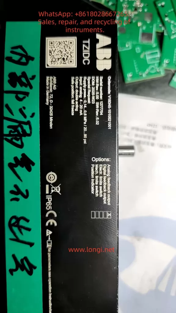
The ABB TZIDC series of intelligent electro-pneumatic positioners are widely used closed-loop position control devices in industrial process control. They are primarily used to convert 4-20 mA analog signals (or fieldbus signals) into precise pneumatic outputs, thereby driving pneumatic actuators to achieve precise positioning of valves or dampers. Unlike traditional I/P proportional converters, the TZIDC features a built-in microprocessor, position sensor, and adaptive control algorithm, enabling automatic calibration, fault diagnosis, and position feedback output. This article is based on the official TZIDC technical manuals (OI/TZIDC-110/TZIDC-120-EN, 45/18-79-EN configuration parameterization manual, and TZIDC-200 series electrical connection specifications), combined with actual test scenarios. It provides a systematic technical analysis covering equipment principles, mechanical installation, electrical wiring, power supply calculations, port signal types, and complete function testing procedures. The content includes parameter group configuration, Autoadjust algorithms, error code diagnosis, and maintenance points, aiming to provide direct operational references for engineers and technicians.
I. Equipment Principles and Core Component Analysis
The TZIDC positioner is essentially an integrated system of electro-pneumatic conversion and closed-loop feedback control. Its core workflow is as follows: The external 4-20 mA setpoint signal is input via terminals +11/-12, which simultaneously provides loop power to the device (two-wire system, typical voltage drop 10-11 V). The internal I/P module (current-to-pressure converter) converts the current signal into a proportional pneumatic output of 0.2-1 bar (or 3-15 psi) to the actuator’s OUT1 (single-acting) or OUT1/OUT2 (double-acting) ports. The position sensor monitors the actual stroke of the actuator in real-time, converting the mechanical rotation of the feedback shaft into an internal analog voltage signal. The microprocessor (CPU) compares the setpoint with the actual position at a sampling rate of 20 ms, calculates the deviation, and dynamically adjusts the pneumatic output to achieve high-precision control with a dead zone <0.3% and linearity ≤0.5%.
The essential difference from a simple proportional pressure valve lies in the fact that the TZIDC features adaptive PID control (automatic optimization of KP, TV parameters), tolerance band adjustment (TOL_BAND adjustable from 0.3-10%), stroke time setting (0-200 s), and multiple characteristic curves (linear, equal percentage 1:25/1:50, or custom 20 points). Air consumption is <0.03 kg/h, and the output capacity reaches 13 kg/h at a 6 bar supply. It supports single/double-acting actuators as well as spring-return/bidirectional actuators. The ambient temperature range is -30 to +85 °C, with an IP65 protection rating and explosion-proof certifications including ATEX Ex i / Ex ec, IECEx, and FM/CSA.
II. Mechanical Installation Principles for Actuators and Feedback Shafts
The actuator is a pneumatic drive device used to convert pneumatic pressure into mechanical displacement or rotational motion. Common types include linear cylinders (piston type, stroke 10-300 mm) and rotary cylinders (vane or gear type, rotation angle 90°/180°). The TZIDC must be installed on the actuator to form a complete control loop: the positioner is fixed via a mounting bracket (NAMUR standard or VDI/VDE 3845), and the feedback shaft is mechanically connected to the actuator’s output rod/shaft.
The feedback shaft is a pure mechanical component with a diameter of approximately 10 mm. It has a flat positioning surface on its circumference and can only be installed in one direction. During installation, the feedback shaft arrow must be within the sensor marking range (±28° for linear actuators, ±57° for rotary actuators, minimum angle 25°). When the actuator moves, the feedback shaft rotates synchronously, driving an internal slot-type position sensor (non-contact, typically Hall effect or optical principle) to generate an analog signal. This signal range corresponds to 0-100% stroke. Exceeding this range triggers ERROR 3 (position out of sensor range), and the device automatically switches to a safe position.
Detailed Installation Steps:
- Pre-adjust the feedback shaft to the zero position (align the arrow with the center mark).
- Connect the lever: Use DIN/IEC 534 brackets for linear actuators and VDI/VDE 3845 adapters for rotary actuators.
- Fix the screws with a torque of 4-6 Nm to ensure no backlash.
- Manually rotate the actuator to both end limits. Check the angle value displayed on the LCD in mode 1.3 (MAN_SENS) to confirm it is >25° and symmetrical.
- If the actuator is not connected, manually rotating the feedback shaft can simulate a test, but actual stroke time and control parameters will deviate due to the lack of load.
Improper installation can cause zero drift >4% (ALARM 3) or sensor range utilization <10% (information code RNG_ERR), which must be corrected before Autoadjust.
III. Detailed Explanation of Electrical Wiring and Port Signal Types
The TZIDC adopts a modular terminal design. The main loop +11/-12 is the only mandatory port; the rest are optional modules (Analog Feedback, Digital Feedback, Shutdown). Ports are strictly categorized as input/output with fixed polarity (+ positive, – negative). Wire cross-section is 0.5-2.5 mm², and screw terminal torque is 0.5 Nm.
- Main Input Ports +11/-12: Analog input (4-20 mA, two-wire loop power supply). The input signal provides power simultaneously (minimum 10 V voltage drop, typically 11 V @ 20 mA), with an effective current range of 3.8-20.5 mA. Exceeding this range triggers ALARM 2 (setpoint out of range).
- Analog Output Ports +31/-32: Output (4-20 mA, corresponding to 0-100% position). It can be set in segments, with direct/reverse action and characteristic deviation <1%. During testing, connect a multimeter in mA mode in series to directly read the position feedback.
- Digital Limit Output Ports +41/-42 and +51/-52:
- Basically outputs (NAMUR compatible, 5-11 V DC, logic 0: <1.2 mA, logic 1: >2.1 mA).
- If a 24 V micro-switch module is selected, then +43/+53 are additional inputs (power supply 8-24 V DC), and 41/42/51/52 are NC/NO contact outputs (max 2 A).
- Proximity switches are pure outputs and do not require external power.
- Parameters P3.1/P3.2 set the switch points (0-100%), and P3.4/P3.5 set the effective direction.
- Digital Input Ports +81/-82: Input (12-24 V DC, current ≤4 mA). Used to externally trigger a safe position or disable control (function set by parameter P4.0).
- Digital Output Ports +83/-84: Output (NAMUR alarm contacts). Trigger conditions include leakage, timeout, zero drift, etc. (parameter group P5).
Wiring Notes: All signal loops must be electrically isolated. Cable shielding should be grounded at both ends (length <1 m). Explosion-proof types must comply with Ui ≤30 V and Ii ≤100 mA. HART communication superimposes FSK signals via +11/-12 without requiring additional ports.
IV. Power Supply Calculation and Loop Testing Methods
The TZIDC is a two-wire loop-powered device and cannot be directly connected to a voltage source. The internal equivalent resistance is ≈550 Ω (11 V @ 20 mA). The correct power supply formula is:
Loop Current I = (V_supply – V_drop) / (R_external + R_internal)
Recommended V_supply = 24 V DC (range 12-45 V for non-Ex environments), V_drop = 11 V, R_internal = 550 Ω.
Calculation Example:
- Target 20 mA (100% position): R_external = (24 – 11) / 0.02 = 650 Ω (a standard 680 Ω resistor is recommended; actual current ≈19.1 mA).
- Target 4 mA (0% position): Use a variable resistor (1-5 kΩ potentiometer), gradually decreasing from high resistance.
- Minimum start-up voltage: 12 V (if <10 V, ERROR 10 is triggered, and the device resets automatically).
Testing Steps:
- Use a 4-20 mA signal generator (e.g., Fluke 707) to output directly, or connect a 24 V supply + variable resistor + multimeter in series for monitoring.
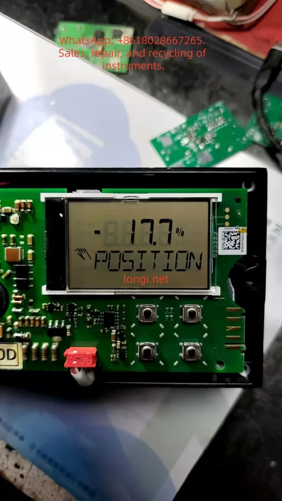
- Apply 12 mA; the LCD should light up and display the position (if a negative value like -81.7% appears, it indicates the feedback shaft is not calibrated).
- Measure the voltage drop across +11/-12 (should be ≥10 V).
- If the current is 9.8 mA but the display shows -81.7%, enter mode 1.3 and manually rotate the feedback shaft to verify sensor response.
V. Parameter Configuration and Autoadjust Debugging Process
Enter configuration level: Press ↑↓ + ENTER simultaneously (countdown 3→0). Parameters are divided into 11 groups (P1 Standard ~ P11 Safe Position).
Key Process:
- P1.0 ACTUATOR: Select LINEAR/ROTARY.
- P1.1 AUTO_ADJ: Start adaptive adjustment (FULL/STROKE/CTRL_PAR/ZERO_POS modes). The process involves 10-200 steps (exhaust, stroke time measurement, PID optimization); success is indicated by “COMPLETE”.
- P1.2 TOL_BAND: Tolerance band (default 0.3%).
- P1.3 TEST: 2-minute simulation test.
- P1.4 EXIT → NV_SAVE to save.
- P2 Group (Setpoint): MIN_RGE/MAX_RGE (segmentation 20-100%), CHARACT (characteristic curve), ACTION (direct/reverse), SHUT_CLS/SHUT_OPN (shutdown values 0-20%), RAMP UP/DN (ramp time).
- P3 Group (Operating Range): MIN_RGE/MAX_RGE (stroke limits).
- P4-P5 Groups: Digital I/O and alarms (LEAKAGE, TIME_OUT, STRK_CTR).
- P7 Group: Control parameters (KP UP/DN, TV UP/DN, GOPULSE, Y-OFS).
- P8-P10: Analog/digital output and input configuration.
- P11: FAIL_POS (safe position: air vent or block).
VI. Full-Process Function Testing Methods
- Basic Response Test:
- Mode 1.0 (Adaptive Control): Change input 4-20 mA; position following error should be <0.5%.
- Mode 1.2 (Manual Stroke): Press ↑↓ to adjust; observe the actuator moving smoothly.
- Mode 1.3 (Manual Sensor): Verify that feedback shaft rotation corresponds to the angle display.
- Analog Output Test (+31/-32):
- At 50% position, the output should be ≈12 mA; characteristic deviation ≤1%.
- Digital Limit Output Test (+41/-42, +51/-52):
- Move to the set threshold; the switch state should flip (use a multimeter to check continuity or NAMUR current).
- Digital Input Test (+81/-82):
- Apply 24 V DC; observe the actuator switching to FAIL_POS.
- Digital Output Alarm Test (+83/-84):
- Simulate a timeout (TIME_OUT) or leakage; the contacts should close.
- HART Diagnostics: Use a communicator to read PV, SV, TV, QV; check for zero drift and stroke counter.
VII. Fault Diagnosis and Maintenance Points
Common Error Codes (LCD or HART):
- ERROR 0/10: Power interruption or voltage <10 V → Check loop voltage.
- ERROR 3: Position out of sensor range → Perform Autoadjust again.
- ERROR 4: EEPROM access failed → Load factory settings (FACT_SET).
- ALARM 1: Actuator leakage → Check pipelines.
- ALARM 3: Zero drift >4% → Perform mechanical installation correction.
- TIMEOUT: Stroke time exceeds 200 s → Increase air pressure or use a booster.
Maintenance:
- Check the air filter every 3 months (plastic filter element, DIN/ISO 8573-1 Class 3).
- Replace the I/P module filter element (remove the main board, torque 350 Ncm).
- Run Autoadjust annually to update parameters.
- Vibration impact is ≤±1% (10 g, 80 Hz); mounting position has no effect.
VIII. Application Cases and Engineering Precautions
In control valve applications in petrochemical plants, the TZIDC works with linear actuators to achieve precise flow regulation: at a setpoint of 12 mA (50% opening), the actual position deviation is <0.3%, and the response time is <2 s. In a butterfly valve application with a double-acting rotary actuator, P2.3 ACTION is set to REVERSE, and SHUT_CLS is set to 15% to prevent jamming.
Precautions:
- Air must be oil-free and water-free (dew point at least 10 K below the operating temperature).
- Wiring for explosion-proof types must strictly follow FM installation drawing 901265.
- Parameters must be saved with NV_SAVE before exiting; otherwise, they will be lost upon reboot.
- Option modules cannot occupy the same slot simultaneously (Shutdown conflicts with Digital Feedback).
IX. Conclusion and Extended Applications
The ABB TZIDC achieves comprehensive functionality from simple positioning to intelligent diagnostics through its mechanical feedback shaft, closed-loop PID control, and modular port design. Its essence as a non-proportional valve lies in its adaptive and feedback mechanisms, which greatly enhance process control reliability. In actual engineering, combining it with HART DTM or SMART VISION software enables remote configuration and further expansion into SIL 2 safety instrumented systems.
Through the installation, wiring, power supply calculation, parameter configuration, and multi-mode testing procedures described in this article, technicians can independently complete equipment verification and troubleshooting. It is recommended to regularly download the latest firmware from the ABB Library (via QR code scan) to ensure compatibility and safety. The application of this positioner in industries such as oil refining, chemical processing, and power generation proves that its precision, reliability, and maintenance convenience far exceed traditional equipment, making it a core component for Industrial 4.0 valve intelligence.